Module And Assembly For Fiber Optic Interconnections
Case; Richard L.
U.S. patent application number 16/840623 was filed with the patent office on 2020-10-08 for module and assembly for fiber optic interconnections. The applicant listed for this patent is CommScope, Inc. of North Carolina. Invention is credited to Richard L. Case.
| Application Number | 20200319421 16/840623 |
| Document ID | / |
| Family ID | 1000004914879 |
| Filed Date | 2020-10-08 |

| United States Patent Application | 20200319421 |
| Kind Code | A1 |
| Case; Richard L. | October 8, 2020 |
MODULE AND ASSEMBLY FOR FIBER OPTIC INTERCONNECTIONS
Abstract
A module for interconnecting fiber optic cables and/or cords includes: a housing having a rear wall; a plurality of MPO adapters mounted in the rear wall; and forty-eight fiber optic adapters mounted to a front portion of the housing, the duplex adapters being operatively connected with the MPO adapters.
| Inventors: | Case; Richard L.; (Omaha, NE) | ||||||||||
| Applicant: |
|
||||||||||
|---|---|---|---|---|---|---|---|---|---|---|---|
| Family ID: | 1000004914879 | ||||||||||
| Appl. No.: | 16/840623 | ||||||||||
| Filed: | April 6, 2020 |
Related U.S. Patent Documents
| Application Number | Filing Date | Patent Number | ||
|---|---|---|---|---|
| 15888835 | Feb 5, 2018 | 10613285 | ||
| 16840623 | ||||
| 14995966 | Jan 14, 2016 | 9885845 | ||
| 15888835 | ||||
| 62103850 | Jan 15, 2015 | |||
| Current U.S. Class: | 1/1 |
| Current CPC Class: | G02B 6/4452 20130101; G02B 6/3897 20130101 |
| International Class: | G02B 6/44 20060101 G02B006/44; G02B 6/38 20060101 G02B006/38 |
Claims
1. A module for interconnecting fiber optic cables and/or cords, comprising: a housing having a rear wall; a plurality of MPO adapters mounted in the rear wall; forty-eight fiber optic adapters mounted to a front portion of the housing, the fiber optic adapters being operatively connected with the MPO adapters.
2. The module defined in claim 1, wherein the plurality of MPO adapters is three adapters.
3. The module defined in claim 1, wherein the plurality of MPO adapters is four adapters.
4. The module defined in claim 1, configured to be oriented in an upright or an inverted orientation, and further comprising a faceplate indicating the upright and inverted orientations.
5. The module defined in claim 1, further comprising latches that are configured to enable the module to be snap-mounted to a shelf.
6. The module defined in claim 1, wherein the forty-eight fiber optic adapters comprise 24 duplex fiber optic adapters.
7. An assembly for interconnecting fiber optic cables and/or cords, comprising: a 1U telecommunications shelf; and two fiber optic telecommunications modules mounted to the shelf, each comprising: a housing having a rear wall; a plurality of MPO adapters mounted in the rear wall; forty-eight fiber optic adapters mounted to a front portion of the housing, the fiber optic adapters being operatively connected with the MPO adapters.
8. The assembly defined in claim 7, wherein the plurality of MPO adapters is three adapters.
9. The assembly defined in claim 7, wherein the plurality of MPO adapters is four adapters.
10. The assembly defined in claim 7, wherein each of the modules is configured to be oriented in an upright or an inverted orientation, and wherein each module further comprises a faceplate indicating the upright and inverted orientations.
11. The assembly defined in claim 7, wherein each module further comprises latches that snap-mount the module to the shelf.
12. The assembly defined in claim 11, wherein the shelf includes at least one window with side edges, and wherein the latches of the modules engage the side edges of the window.
13. The assembly defined in claim 7, wherein the forty-eight fiber optic adapters comprise 24 duplex fiber optic adapters.
14. An assembly for interconnecting fiber optic cables and/or cords, comprising: a 1U telecommunications shelf having a window with side edges; and two fiber optic telecommunications modules mounted to the shelf, each comprising: a housing having a rear wall; a plurality of MPO adapters mounted in the rear wall; forty-eight fiber optic adapters mounted to a front portion of the housing, the fiber optic adapters being operatively connected with the MPO adapters; and latches that engage the side edges of the window to snap-mount the module to the shelf; wherein each of the modules is configured to be oriented in the shelf in an upright or an inverted orientation, and wherein each module further comprises a faceplate indicating the upright and inverted orientations.
15. The assembly defined in claim 14, wherein the plurality of MPO adapters is three adapters.
16. The assembly defined in claim 14, wherein the plurality of MPO adapters is four adapters.
17. The assembly defined in claim 14, wherein the forty-eight fiber optic adapters comprise 24 duplex fiber optic adapters.
Description
RELATED APPLICATION
[0001] The present application is a Continuation of U.S. patent application Ser. No. 15/888,835, filed Feb. 5, 2018; which is a Continuation of U.S. patent application Ser. No. 14/995,966, filed Jan. 14, 2016, now U.S. Pat. No. 9,885,845; which claims priority from and the benefit of U.S. Provisional Patent Application No. 62/103,850, filed Jan. 15, 2015, the disclosures of which are hereby incorporated herein in their entirety.
FIELD OF THE INVENTION
[0002] The present invention is directed to datacommunications equipment, and in particular datacommunications equipment for fiber optic interconnections.
BACKGROUND
[0003] A network patching system is typically used to interconnect the various communication lines within a closet or computer room. In a conventional network patching system, the communication lines are terminated within a closet in an organized manner via one or more patch panels mounted on a rack or frame. Multiple ports are included in the patch panel, typically in some type of organized array. Each of the different ports is connected with a communications line. In small patching systems, all communications lines may terminate on the patch panels of the same rack. In larger patching systems, multiple racks may be used, wherein different communications lines terminate on different racks. Interconnections between the various communications lines are made connecting patch cords to the ports. By selectively connecting the various communications lines with patch cords, any combination of communications lines can be interconnected.
[0004] It may be desirable to provide different devices for interconnecting datacommunications lines.
SUMMARY
[0005] As a first aspect, embodiments of the invention are directed to a module for interconnecting fiber optic cables and/or cords. The module comprises: a housing having a rear wall; a plurality of MPO adapters mounted in the rear wall; and forty-eight fiber optic adapters mounted to a front portion of the housing, the fiber optic adapters being operatively connected with the MPO adapters.
[0006] As a second aspect, embodiments of the invention are directed to an assembly for interconnecting fiber optic cables and/or cords comprising a 1U telecommunications shelf and two fiber optic telecommunications modules mounted to the shelf. Each of the modules comprises: a housing having a rear wall; a plurality of MPO adapters mounted in the rear wall; and forty-eight fiber optic adapters mounted to a front portion of the housing, the fiber optic adapters being operatively connected with the MPO adapters.
[0007] As a third aspect, embodiments of the invention are directed to an assembly for interconnecting fiber optic cables and/or cords comprising a 1U telecommunications shelf having a window with side edges and two fiber optic telecommunications modules mounted to the shelf. Each module comprises: a housing having a rear wall; a plurality of MPO adapters mounted in the rear wall; forty-eight fiber optic adapters mounted to a front portion of the housing, the fiber optic adapters being operatively connected with the MPO adapters; and latches that engage the side edges of the window to snap-mount the module to the shelf. Each of the modules is configured to be oriented in the shelf in an upright or an inverted orientation, and wherein each module further comprises a faceplate indicating the upright and inverted orientations.
BRIEF DESCRIPTION OF THE FIGURES
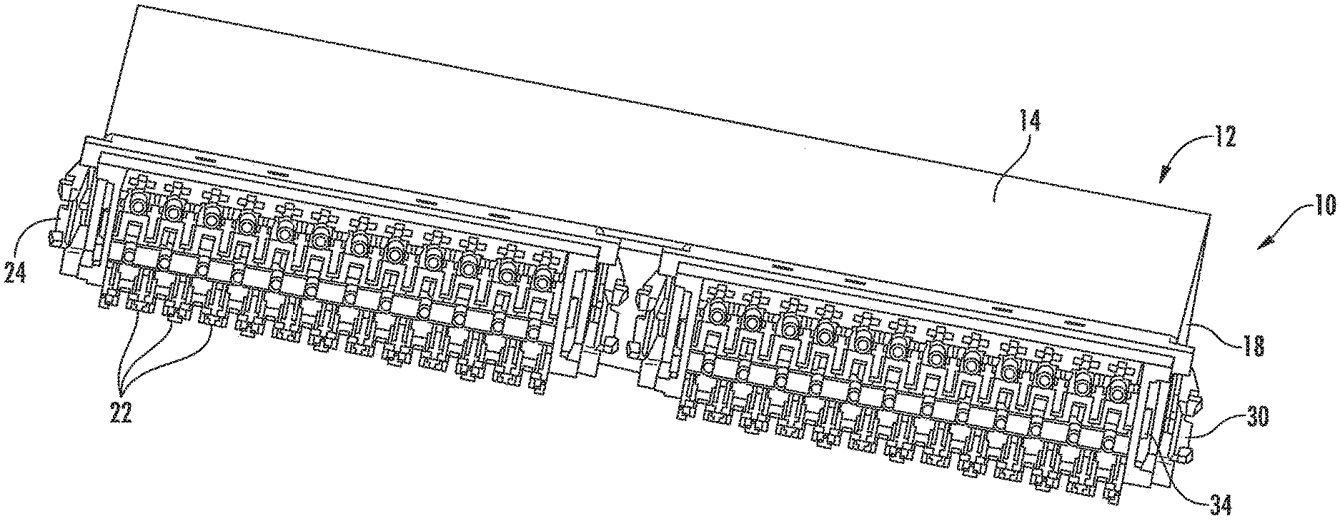
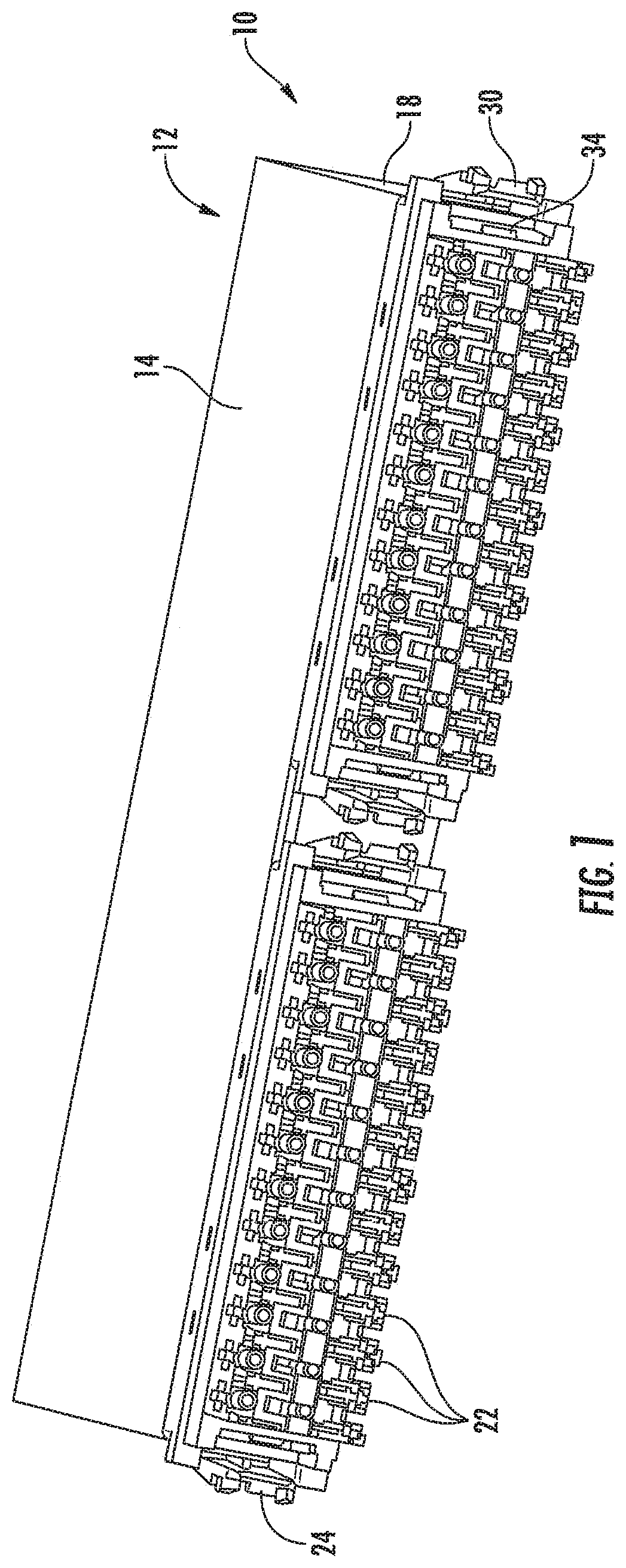
[0008] FIG. 1 is a front perspective view of a module for interconnecting fiber optic cables and cords according to embodiments of the invention.
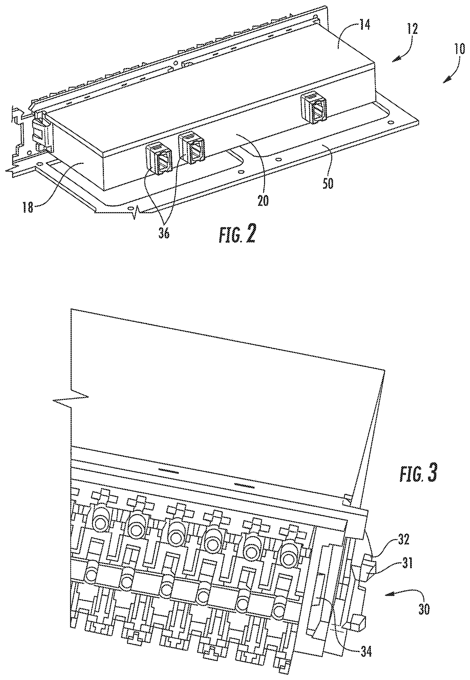
[0009] FIG. 2 is a rear perspective view of the module of FIG. 1.
[0010] FIG. 3 is an enlarged partial front perspective view of one of the latches of the module of FIG. 1 used to attach the module to a fiber shelf.
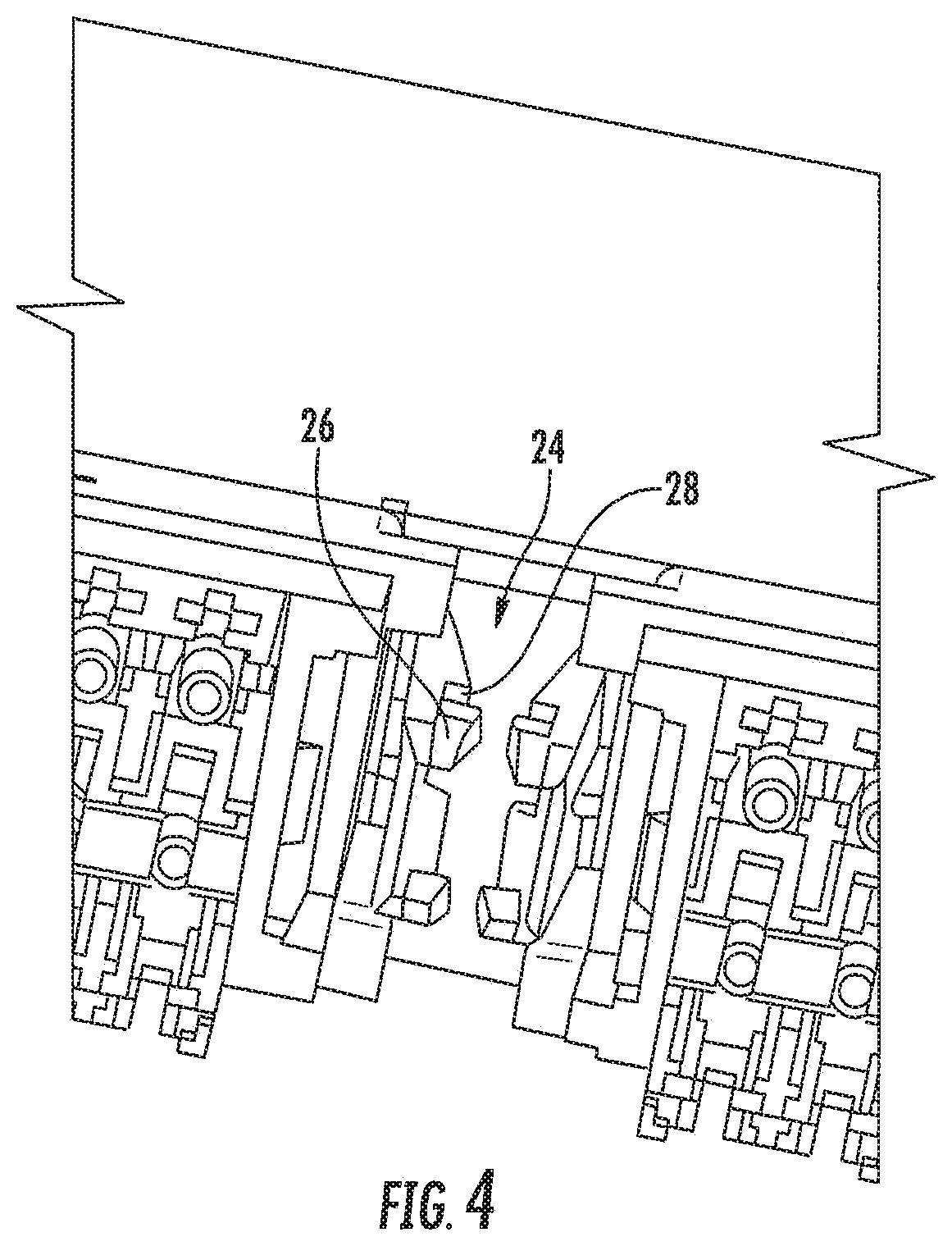
[0011] FIG. 4 is an enlarged partial front perspective view of another of the latches of the module of FIG. 1 used to attach the module to a fiber shelf.
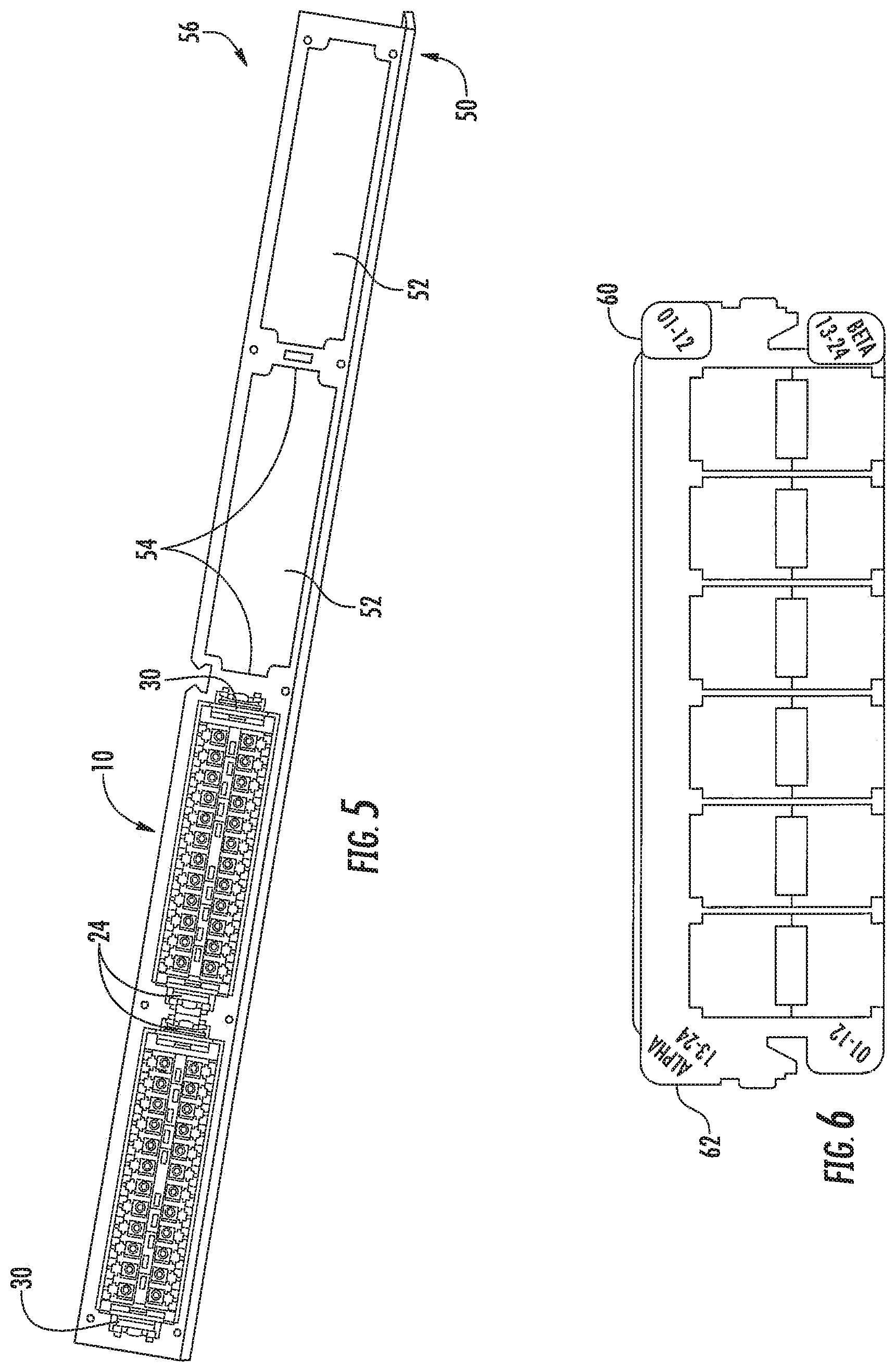
[0012] FIG. 5 is front perspective view of the module of FIG. 1 attached to a fiber shelf.
[0013] FIG. 6 is a front view of a labeling plate attached to the front side of the module of FIG. 1.
[0014] FIG. 7 is a rear perspective view of an alternative embodiment of a module for interconnecting fiber optic cables and cords.
DETAILED DESCRIPTION
[0015] The present invention is described with reference to the accompanying drawings, in which certain embodiments of the invention are shown. This invention may, however, be embodied in many different forms and should not be construed as limited to the embodiments that are pictured and described herein; rather, these embodiments are provided so that this disclosure will be thorough and complete, and will fully convey the scope of the invention to those skilled in the art. It will also be appreciated that the embodiments disclosed herein can be combined in any way and/or combination to provide many additional embodiments.
[0016] Unless otherwise defined, all technical and scientific terms that are used in this disclosure have the same meaning as commonly understood by one of ordinary skill in the art to which this invention belongs. The terminology used in the below description is for the purpose of describing particular embodiments only and is not intended to be limiting of the invention. As used in this disclosure, the singular forms "a", "an" and "the" are intended to include the plural forms as well, unless the context clearly indicates otherwise. It will also be understood that when an element (e.g., a device, circuit, etc.) is referred to as being "connected" or "coupled" to another element, it can be directly connected or coupled to the other element or intervening elements may be present. In contrast, when an element is referred to as being "directly connected" or "directly coupled" to another element, there are no intervening elements present.
[0017] Referring now to FIGS. 1 and 2, a telecommunications module for interconnecting fiber optic cables and cords, designated broadly at 10, is shown therein. The module 10 includes a box-like housing 12 with a ceiling 14, a floor (not shown), side walls 18, and a rear wall 20. The housing 12 is sized to mount on a shelf sized at 1U (i.e., approximately 1.75 inches in height). On its front side, the module 10 includes two sets of 24 duplex fiber optic adapters 22. Each set of fiber optic adapters 22 is arranged in upper and lower rows of twelve adapters each, with the sets of adapters 22 being side-by-side across the front of the module 10. The adapters 22 are conventional fiber optic adapters and need not be described in detail herein.
[0018] Referring now to FIGS. 1 and 4, the front side of the module 10 also includes features that enable the module 10 to be attached to a 1U fiber shelf 50. A pair of snap latches 24 are located between the sets of adapters 22 and project forwardly. Each of the snap latches 24 has a hook 26 and an opposed shoulder 28 that enables it to receive a vertical edge of the shelf 50. In addition, a latch 30 (FIG. 3) projects forwardly from each of the lateral edges of the module 10; each latch 30 includes a hook 31 and a shoulder 32 that can receive a vertical edge of the shelf 50.
[0019] Referring now to FIGS. 1 and 3, the front side of the module 10 also includes two latching projections 34 that are located on opposite sides of the sets of adapters 22. These latching projections 34 enable the module to mount a kit for "intelligent patching" (i.e., a system that can track connectivity of cords and cables connected to the adapters 22). An exemplary system/kit is the iPATCH.RTM. system, available from CommScope, Inc., (Hickory, N.C.).
[0020] Referring now to FIG. 2, three MPO connectors 36 are mounted to the rear wall 20 of the housing 12. These MPO connectors 36 are sixteen fiber connectors that receive a sixteen fiber MPO attached to a fiber optic cable.
[0021] The housing 12 protects optical fibers (not shown) that extend between the MPO connectors 36 and the adapters 22. There are multiple arrangements of such fibers known to those of skill in this art that need not be described in detail herein.
[0022] FIG. 5 illustrates the module 10 mounted in the shelf 50. As can be seen in FIG. 5, the shelf 50 includes four windows 52 with vertical side edges 54 (only two windows 52 are visible in FIG. 5). The module 10 is mounted on the shelf 50 by inserting the adapters 22 through the windows 50; the latches 24 contact the side edges 54 and deflect, then recover, as the module 10 is moved forward to snap-mount the module 10 on the shelf 50. The side edges 54 of the window 50 are captured between the hooks 26 and the shoulders 28 of the latches 24. Similarly, the latches 30 engage respective side edges 54 of the window 50 and deflect, then recover to capture the side edges 54 between the hooks 31 and the shoulders 32. The latching projections 34 are free to receive an intelligent patching kit if desired. The resulting assembly 56 comprising the shelf 50 and two modules 10 can be mounted within a 1U space on a conventional telecommunications rack or cabinet.
[0023] FIG. 6 shows the module 10 with a faceplate 60 attached thereto for assisting with orientation of the module 10. As discussed at length in U.S. Pat. No. 7,416,347, the disclosure of which is hereby incorporated herein in its entirety, fiber optic modules often have an "ALPHA" or "BETA" orientation in order to provide proper connectivity for the fibers connected thereto. The faceplate 60 includes indicia 62 that is oriented so that an operator can quickly discern an "ALPHA" or "BETA" configuration of the module 10 irrespective of whether the module 10 is horizontally or vertically oriented.
[0024] FIG. 7 illustrates another fiber optic module 110 according to embodiments of the invention. The module 110 includes three TAP connectors 136 on its rear wall 120.
[0025] It should also be noted that, because the modules 10, 110 include 48 fiber optic adapters 22, they are configured to be able to receive either three 16-fiber MPOs or four 12-fiber MPOs. As such, the modules can be employed through transitions between 12-fiber based systems and 16-fiber based systems. Thus, as higher data transmission speeds (such as 40 Gb, 100 Gb, or even 400 Gb) become more standard and/or commonplace, the modules can be modified to address the changing needs of end users.
[0026] The foregoing is illustrative of the present invention and is not to be construed as limiting thereof. Although exemplary embodiments of this invention have been described, those skilled in the art will readily appreciate that many modifications are possible in the exemplary embodiments without materially departing from the novel teachings and advantages of this invention. Accordingly, all such modifications are intended to be included within the scope of this invention as defined in the claims. The invention is defined by the following claims, with equivalents of the claims to be included therein.
* * * * *
D00000
D00001
D00002
D00003
D00004
D00005
XML
uspto.report is an independent third-party trademark research tool that is not affiliated, endorsed, or sponsored by the United States Patent and Trademark Office (USPTO) or any other governmental organization. The information provided by uspto.report is based on publicly available data at the time of writing and is intended for informational purposes only.
While we strive to provide accurate and up-to-date information, we do not guarantee the accuracy, completeness, reliability, or suitability of the information displayed on this site. The use of this site is at your own risk. Any reliance you place on such information is therefore strictly at your own risk.
All official trademark data, including owner information, should be verified by visiting the official USPTO website at www.uspto.gov. This site is not intended to replace professional legal advice and should not be used as a substitute for consulting with a legal professional who is knowledgeable about trademark law.