Suppressor Apparatus And Apparatus And Method For Optimizing And Cleaning A Suppressor
Riley; Bradford Whittam
U.S. patent application number 16/209726 was filed with the patent office on 2020-10-08 for suppressor apparatus and apparatus and method for optimizing and cleaning a suppressor. The applicant listed for this patent is HiPerformance, LLC. Invention is credited to Bradford Whittam Riley.
| Application Number | 20200318927 16/209726 |
| Document ID | / |
| Family ID | 1000005104304 |
| Filed Date | 2020-10-08 |


| United States Patent Application | 20200318927 |
| Kind Code | A9 |
| Riley; Bradford Whittam | October 8, 2020 |
SUPPRESSOR APPARATUS AND APPARATUS AND METHOD FOR OPTIMIZING AND CLEANING A SUPPRESSOR
Abstract
A suppressor (20) includes a suppressor body (22) with an internal suppression chamber (36A) defining an interior passageway (36) for the transmission of projectiles. The inner surface (26) includes an inner threaded surface (32) for movably and threadably receiving a plurality of baffles (50) having outer threads (52). The inner threaded surface (32) extends over a large majority of the length of the internal suppression chamber (36A) defined inside the suppressor body (22) and in common with a large portion of the interior passageway (36). The baffles (50) are threaded into desired locations with a baffle tool (80), and their locations are adjusted to change internal chamber (38) size and optimize the suppressor (20) to the operational parameters of a given firearm and its ammunition. The baffles (50) also include cleaning thread gaps (56) spaced around the circumference of the baffles (50). The suppressor 20 is either permanently or removably mounted to a firearm muzzle or other output of a noise generating item.
| Inventors: | Riley; Bradford Whittam; (Olathe, KS) | ||||||||||
| Applicant: |
|
||||||||||
|---|---|---|---|---|---|---|---|---|---|---|---|
| Prior Publication: |
|
||||||||||
| Family ID: | 1000005104304 | ||||||||||
| Appl. No.: | 16/209726 | ||||||||||
| Filed: | December 4, 2018 |
Related U.S. Patent Documents
| Application Number | Filing Date | Patent Number | ||
|---|---|---|---|---|
| 62594372 | Dec 4, 2017 | |||
| Current U.S. Class: | 1/1 |
| Current CPC Class: | F41A 21/30 20130101 |
| International Class: | F41A 21/30 20060101 F41A021/30 |
Claims
1. A sound suppressor (20) comprising: a suppressor body (22) including an outer surface (24), and inner surface (26), a length extending between a muzzle end (28), a discharge end (30), and defining an interior passageway (36) extending from the muzzle end to the discharge end; the inner surface (26) comprises a inner threaded surface (32); at least one baffle including an outer threaded surface (52) for threaded engagement with the inner threaded surface of the suppressor body, and the at least one baffle including an interior baffle passageway (54) through the at least one baffle; wherein the at least one baffle is threaded into the suppressor body between the muzzle end and the discharge end to create a plurality of interior chambers inside the suppressor body, and a discharge-end cap fitted on the discharge end of the suppressor body and including an interior cap passageway through the discharge-end cap.
2. The suppressor of claim 1 wherein the baffle comprises a muzzle surface comprising a protruding nipple extending over a nipple length to define an elongated open ring surrounding the nipple, the open ring being operable to temporarily trap discharge gases being discharged through the suppressor.
3. (canceled)
4. (canceled)
5. A suppressor comprising an elongated body with an outer surface and an inner surface; the body includes a muzzle end for attachment to a firearm, a discharge end opposite the muzzle end, and the body defines an interior passageway to transmit a projectile; the inner surface includes a plurality of generally annular ridges operable to create turbulent flow of discharge gases from the firearm.
6. The suppressor of claim 5 wherein the ridges comprise threads.
7. The suppressor of claim 6 further comprising a plurality of removable insert baffles threaded into the body at spaced locations along a length of the body.
8. The suppressor of claim 7 further comprising an end cap threaded into the discharge end.
9. The suppressor of claim 7 wherein the baffles comprise a muzzle surface facing the muzzle end, the muzzle surface including an elongated nipple.
10. The suppressor of claim 7 wherein the baffles comprise a muzzle surface facing the muzzle end, the muzzle surface including a concave arc.
11. A suppressor comprising an elongated body with an outer surface and an inner surface; the body includes a muzzle end for attachment to a firearm, a discharge end opposite the muzzle end, and the body defines an interior passageway to transmit a projectile; the inner surface includes an inner threaded surface; a plurality of baffles having an outer baffle thread threadably engaged in the inner threaded surface, and the baffles including cleaning thread gaps defined in the baffle thread, the thread gaps operable to scrape debris from the inner threaded surface and collect the debris for removal from the suppressor.
12. The suppressor according to claim 11 wherein the thread gaps have a substantially uniform depth along a length of the baffle.
13. The suppressor according to claim 11 wherein the thread gaps have a first depth adjacent a muzzle surface of the baffles, and the first depth being shallow enough that valleys of the outer baffle threads extend through the thread gaps, and having a second depth extending deeper into the baffle creating additional volume for collecting debris during cleaning.
14. (canceled)
15. (canceled)
16. (canceled)
17. (canceled)
18. (canceled)
19. (canceled)
20. (canceled)
21. (canceled)
22. The suppressor of claim 1 wherein the inner threaded surface comprises a mono-thread.
23. The suppressor of claim 1 wherein the inner threaded surface extends over more than about 50% of the length of the suppression chamber.
24. The suppressor of claim 1 wherein the inner threaded surface comprises a thread pitch of 16 or less.
24. The suppressor of claim 1 wherein further comprising second baffle threaded into the supressor body.
25. The suppressor of claim 1 wherein the baffle is positioned in different desired locations for different firearms
26. The suppressor of claim 5 further comprising a baffle held in a desired location by the generally annular ridges.
27. The suppressor of claim 26 wherein the baffle comprises a muzzle firing side having a concave arc.
28. The suppressor of claim 27 wherein the baffles comprise removable baffles.
29. The suppressor of claim 26 wherein the baffle is positioned in different desired locations for different firearms.
30. A suppressor (20) comprising: a suppressor body (22) including an outer surface (24), and inner surface (26), a length extending between a muzzle end (28), a discharge end (30), and defining an interior passageway (36) extending from the muzzle end to the discharge end; at least one baffle including an outer surface (52) for engagement with the inner surface of the suppressor body, and the at least one baffle including an interior baffle passageway (54) through the at least one baffle; and wherein the at least one baffle is placed at a desired location in the suppressor body between the muzzle end and the discharge end to create a plurality of interior chambers inside the suppressor body.
31. The suppressor according to claim 30 further comrising a plurality of baffles positioned in a plurality of desired locations along the length of the suppressor body.
32. The suppressor according to claim 31 wherein the plurality of baffles are positioned in the plurality of locations customized for a firearm.
33. The suppressor according to claim 30 wherein the desired location of the baffle can be changed to customize the suppressor.
Description
CROSS-REFERENCE TO RELATED APPLICATIONS
[0001] This application claims priority on Provisional U.S. patent application Ser. No. 62/594,372, filed Dec. 4, 2017, titled SUPPRESSOR APPARATUS AND APPARATUS AND METHOD FOR OPTIMIZING AND CLEANING A SUPPRESSOR which is hereby incorporated by reference in its entirety.
BACKGROUND
1. Field of the Disclosed Subject Matter
[0002] The present inventions relates to sound suppressors, and more particularly to sound and flash suppressors for firearms.
2. Background
[0003] It is generally known to utilize sound and flash suppressors with firearms to diminish both noise and barrel flash when the weapon is fired. This provides the benefits of hearing and eye protection and may allow the person firing the weapon to avoid detection while firing. A significant number of firearm noise suppressor devices and flash suppressor devices, generally and jointly referred to as suppressors herein, have been developed over the years for use with firearms such as rifles and handguns. In most cases, the suppressors are attached to the barrel of a firearm, by threads for example. In some cases suppressors are constructed integrally with a firearm barrel so as to be a permanent component of the firearm.
[0004] Typically, a suppressor comprises an elongate tubular body that attaches in any suitable manner to a firearm barrel and permits passage of a projectile from the bore of a firearm barrel and through the tubular body of the suppressor. To facilitate noise and flash suppression, a number of internal baffles are typically positioned along the length of the body to create several internal chambers within the body. In various different suppressors, the baffles are stacked in the tube, provided as part of a mono- baffle assembly inserted into the tube, or welding baffles together to form a unitary baffle weldment without a separate tube.
[0005] The baffle partitions are typically spaced apart and have central openings in each baffle partition for projectile passage. The chambers that are defined between the internal baffles cause the discharge gas from the firearm to progress in serial fashion through each of the chambers. The baffles are designed to reflect discharge gas and slow the expansion and progress of gas through the suppressor and increase the dwell time reduing the noise of the gas being exhausted from the suppressor. In general, discharge gas emitted from the bore of the firearm barrel enters the larger volume of the internal chambers of the tubular body and progresses from chamber to chamber, with the gas expanding and its pressure being diminished within each successive chamber thereby reducing the rapid expansion and discharge of gas which normally creates the loud bang we associate with gun fire.
[0006] Known suppressors, however, suffer from multiple drawbacks, including cost of and time required for manufacture, inefficiency in cooling discharge gas, inability to or too difficult to clean, and creating smooth or laminar gas flow through the suppressor. Further, each firearm, even of the same make and caliber, is somewhat unique, and the operational features of firearms also change depending on the features of ammunition, such as load. Known suppressors provide no way to optimize a suppressor to multiple firearms or for different ammunition. Accordingly, it is desirable to provide an enhanced suppressor with improved operation, and it is desirable to provide an optimizable suppressor.
SUMMARY
[0007] There is, therefore, provided in the practice of the invention an improved suppressor having a suppressor body with at least one baffle movably positionable in the suppressor body.
[0008] In accordance with one aspect of the present invention, the suppressor body is internally threaded and the baffle has outer threads. The baffle is threaded into the suppressor body to a desired location to create interior chambers in the suppressor body.
[0009] In accordance with another aspect of the present invention, the location of the baffle is moved to another location to optimize the suppressor for operational parameters of a noise generating item such as a firearm. In other aspects of the invention, each of a plurality of baffles are threaded into the suppressor body each being movably positioned at desired locations, which may be adjusted to optimize the suppressor. In one aspect of the invention, a discharge-end cap is fitted on a discharge end of the suppressor body.
[0010] In accordance with a further aspect of the present invention, the discharge-end cap and baffles are removable for cleaning and optimization. In one aspect the baffles comprise thread gaps operable to scrape off and collect carbon build up as the baffles are threaded out of the suppressor body thereby cleaning the inner threaded surface of the suppressor body.
[0011] In accordance with yet another aspect of the present invention, a baffle tool engages the baffle to rotate the baffle thereby positioning the baffle at a desired location in the suppressor body.
[0012] Accordingly, it is an object of the present invention to provide an improved suppressor, improved method of optimizing a suppressor, improved method of cleaning a suppressor, and an improved tool for optimizing and cleaning a suppressor. There has thus been outlined, rather broadly, certain embodiments of the invention in order that the detailed description thereof herein may be better understood, and in order that the present contribution to the art may be better appreciated. There are, of course, additional embodiments of the invention that will be described below and which will form the subject matter of the claims appended hereto.
[0013] In this respect, before explaining at least one embodiment of the invention in detail, it is to be understood that the invention is not limited in its application to the details of construction and to the arrangements of the components set forth in the following description or illustrated in the drawings. The invention is capable of embodiments in addition to those described and of being practiced and carried out in various ways. Also, it is to be understood that the phraseology and terminology employed herein, as well as the abstract, are for the purpose of description and should not be regarded as limiting.
[0014] As such, those skilled in the art will appreciate that the conception upon which this disclosure is based may readily be utilized as a basis for designing other structures, methods, and systems for carrying out the several purposes of the present invention. It is important, therefore, that the claims be regarded as including such equivalent constructions insofar as they do not depart from the spirit and scope of the present invention. Though some features of the invention may be claimed in dependency, each feature has merit when used independently.
BRIEF DESCRIPTION OF THE DRAWINGS
[0015] FIG. 1 is a perspective, cross-sectional view illustrating a suppressor according to an embodiment of the invention;
[0016] FIG. 2 is a side, cross-sectional view of the suppressor of FIG. 1;
[0017] FIG. 3A is a perspective view of a nipple baffle used in the suppressor of FIG. 1 and illustrating the muzzle facing side of the nipple baffle;
[0018] FIG. 4A is a perspective view of the nipple baffle of FIG. 3A and used in the suppressor of FIG. 1 and illustrating the discharge-end facing side of the nipple baffle;
[0019] FIG. 5A is a perspective view of a baffle tool;
[0020] FIG. 3B is a perspective view of an alternate low profile baffle for use in the suppressor of FIG. 1 and illustrating the muzzle facing side of the baffle;
[0021] FIG. 4B is a perspective view of the alternate low profile baffle of FIG. 3B and for use in the suppressor of FIG. 1 and illustrating the discharge-end facing side of the baffle, and
[0022] FIG. 5B is a perspective view of an alternate two prong baffle tool.
DETAILED DESCRIPTION
[0023] The invention will now be described with reference to the drawing figures, in which like reference numerals refer to like parts throughout. Referring to FIGS. 1 and 2, an embodiment of the improved sound suppressor 20, in accordance with the present invention, provides a suppressor body 22 movably receiving a plurality of baffles 50 therein for suppression of sound. Utilizing a baffle tool 80 (FIG. 5) the individual baffles 50 can be moved to different locations in the suppressor body 22 to change the size of internal chambers 38 inside the suppressor body 22 thereby optimizing the suppressor to a particular sound generating item such as a firearm. The baffle tool 80 is also used to remove the baffles to clean the suppressor 20.
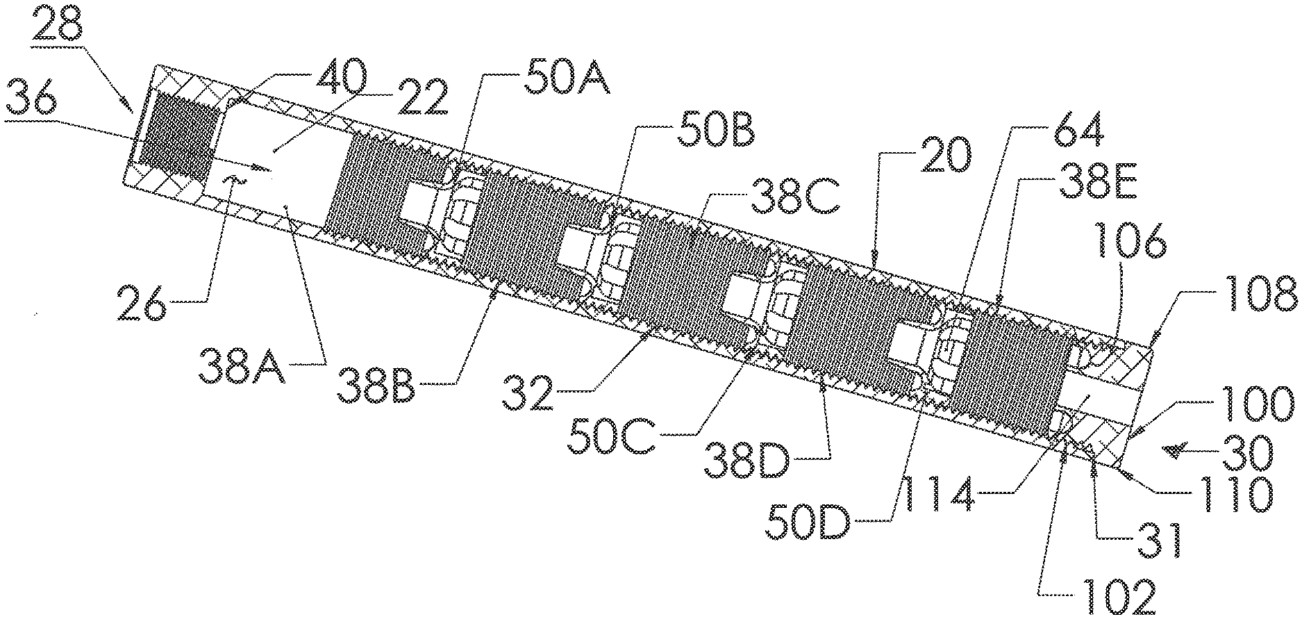
[0024] With continued reference to FIGS. 1 and 2, in an embodiment of the present inventive apparatus, the suppressor includes an elongated, tubular suppressor body 22, which is substantially rigid under the forces encountered when firing a fun and made from materials such aluminum, titanium, steel, or other suitable materials. The suppressor body has outer surface 24 and an inner surface 26 and extends from a muzzle end 28 to a discharge-end 30 with an interior passageway 36 there through for transmission of a projectile and discharge gases from the muzzle end 28 to the discharge-end 30. The interior passageway 36 is central and substantially cylindrical, and a central axis of the suppressor body 22 is defined in the center of the interior passageway 36.
[0025] The muzzle end 28 is configured for attachment to the muzzle of a gun (not shown) or other output from another sound generating item. In the embodiment shown, the muzzle end 28 utilizes muzzle threads 34 to thread onto a gun barrel and is removable for use on another gun. If desired, other attachment mechanisms, bayonet fitting, etc. could be used to attach the muzzle to the end of the gun barrel. Also, the suppressor body 22 could be formed integral to the gun barrel, and alternatively, it could be permanently fixed to the gun barrel.
[0026] The inner surface 26 of the suppressor body 22 includes an inner threaded surface 32 also referred to as suppressor chamber thread. The chamber thread 32 is a mono-thread in one embodiment but multiple threads are used in others. The chamber thread 32 extends over substantially the entire length of the suppressor body 22 starting at the discharge-end and extending to near the muzzle end 28. In one embodiment, the chamber thread 32 extends over more than 50% of the length of the overall suppression chamber. The overall suppression chamber (illustrated by arrow 36A as it is in common with a large portion of the interior passageway 36) extends from the muzzle shoulder 40 to the discharge-end. In another embodiment, the chamber thread 32 extends over approximately 75% of the length of the overall suppression chamber 36A, and in still another embodiment, the chamber thread 32 extends over approximately 80% of the overall suppression chamber 36A. The arrowed lines 36 and 36A also illustrate the central axis of the suppressor body 22. While embodiments could extend the chamber thread up to the muzzle shoulder 40, there is generally no need to make the first internal chamber so small, so the threads stop at about 80% of the length of the overall suppression chamber.
[0027] The chamber thread is a course thread, in one embodiment having a pitch of 16 or less threads per inch. In one embodiment the pitch is 12 threads per inch; in another the pitch is 10 threads per inch or less, and in still another embodiment the pitch is 8 threads per inch. The course threads provide a high interior surface area compared to a smooth wall, and thus, are more efficient at heat transfer out of the internal chambers 38 making the suppressor more efficient and less subject to overheating. This more efficient and rapid heat transfer also increases the cooling rate of the exhaust gas enhancing the sound suppression. Further, the course thread creates more turbulent flow along the interior surface 26 of the suppressor body 22, reducing laminar flow, slowing gas exhaust, and again enhancing the sound suppression of the invention. Alternate embodiments also incorporate fine threads on the suppressor interior.
[0028] To achieve the beneficial heat transfer and turbulent flow of this aspect of the invention, an alternate embodiment uses course annular ridges with 16 or less ridges per inch. The annular ridges can be utilized in other suppressor configurations with stacked baffles and mono baffle configurations. While this embodiment provides the gas cooling and turbulent gas flow benefits to enhance sound suppression, the threaded embodiment provides the additional benefits of inexpensive and fast manufacturing as well as the ability to optimize the suppressor.
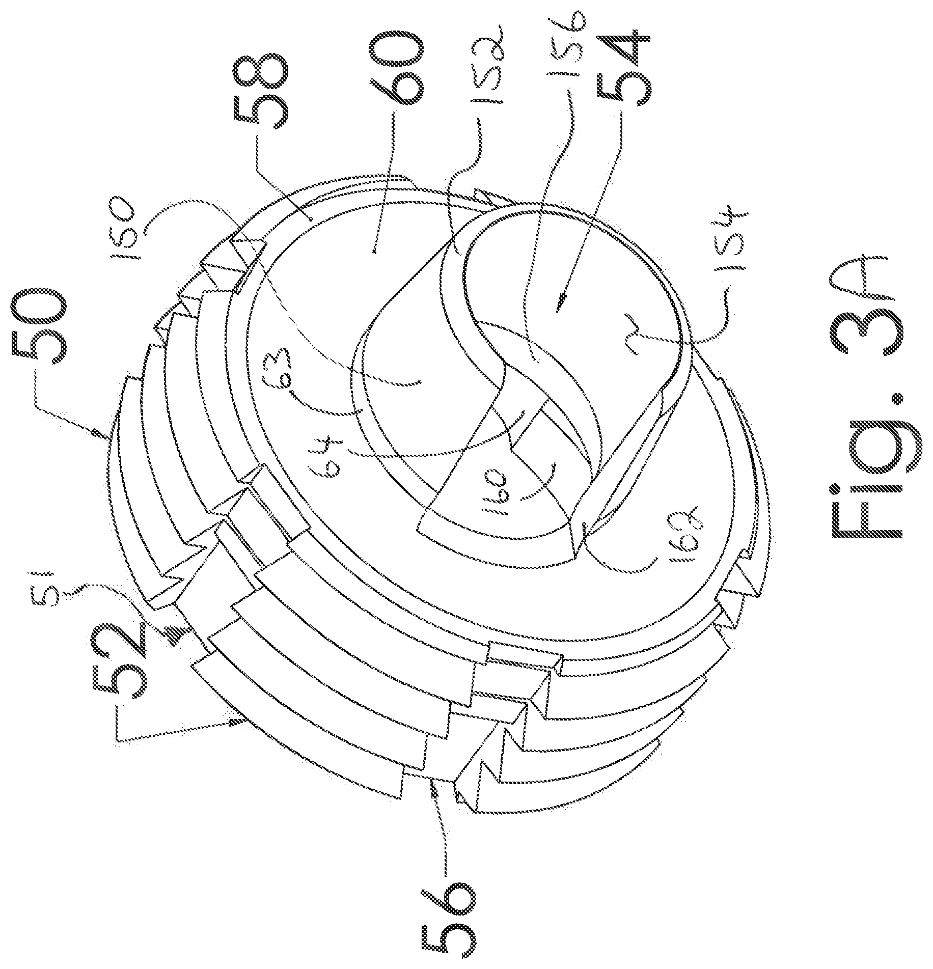
[0029] Referring to FIGS. 1, 3, and 4, a plurality of removable insert baffles 50 are threaded into the suppressor body 22. Each baffle 50 has an outer threaded surface 52 with a baffle thread, which extends across substantially all of their length/thickness. Alternate embodiments utilize a thread only over a portion of the outer surface. The baffle thread 52 is a mono-thread in one embodiment, but alternate embodiments utilize multiple threads to match the threads of the inner threaded surface 32. Each baffle has an interior baffle passageway 54 allowing a projectile to pass through the baffle 50 without substantial interference. In one embodiment the passageway 54 is substantially cylindrical and substantially central to the baffle. The baffle 50 also has a plurality of cleaning thread gaps 56, defined by breaks in the thread. In the embodiment shown there are five thread gaps 56 around the circumference of the baffle. Also the thread gaps extend linearly across the entire length/thickness of the baffle parallel to a central axis of the baffle 50. The thread gaps function to clean the interior of the suppressor body by scraping off carbon deposits and collecting the carbon in the gaps 56 to be carried out of the suppressor body 22.
[0030] The muzzle facing or inlet side 58 of the baffle 50 is illustrated in FIGS. 1 and 3A. The muzzle facing side or muzzle surface 58 of the baffle has a concave arc 60 to it, which enhances sound suppression by creating a turbulent spiral or rolling flow of the gas as opposed to simply impacting a flat wall.
[0031] The discharge-end facing side or discharge surface 62 is generally flat for ease of manufacture, and includes a plurality of holes 64 for engaging with the baffle tool 80. The holes face away from the gas flow and thus away from the muzzle end 28 of the suppressor body 22.
[0032] In a preferred embodiment the threads are a loose fit to reduce or inhibit galling between the chamber thread surfaces 32 and baffle thread surfaces 52. To direct the discharge gases through the central passageway 54, the valley portions of the threads are made deeper, so that the peek portions of the threads extend deep into the valley of the mating threads creating a barrier around the outside of the baffle, inhibiting gas flow around the outside of the baffle; thus inhibiting discharge gas flow between the suppressor body and the baffle. In the embodiment shown, the valley portions of the threads on the baffle extend through the thread gaps 56 adjacent the muzzle surface 60 to maintain the gas flow inhibiting barrier around the outer circumference of the baffle 50. In one embodiment, the thread gaps, defined in the outer threads of the baffle, have a first depth adjacent the muzzle surface of the baffles. The first depth is shallow enough that valleys of the outer baffle threads extend through the thread gaps. The thread gaps also have a second depth extending deeper into the baffle creating additional volume for collecting debris during cleaning. Thus, the thread gaps deepen as they extend toward the discharge side 62 to provide additional volume 51 for cleaning carbon deposits from the interior threads of the suppressor.
[0033] In one embodiment, the first two threads closest to the muzzle side 60 have their valley portions extending across the thread gaps, so that there are at least two circumferential discharge gas barriers around the outside of the baffle. In the alternate embodiment of FIGS. 3B and 4B, the thread gaps 56B are a substantially constant and uniform depth, and the valleys of the threads extend across the thread gaps over the entire length of the baffle creating three or more circumferential discharge gas barriers.
[0034] In one embodiment, referring again to FIGS. 3A and 4A, the muzzle side of the baffle 50 has an elongated nipple 150 extending from the muzzle side toward the muzzle end 28 of the suppressor. The nipple has a nipple length and a tapered tip 152 and a substantially cylindrical and substantially central passageway 154. The nipple, which is generally conical, transitions with a radius 63 into the concave arc 62 of the muzzle side surface 58. The nipple 150 along with the interior surface of the suppressor body defines an elongated ring volume 151 (FIG. 2) to temporarily trap a larger volume of discharge gas on the muzzle side of the baffle in a turbulent flow state. The baffle also has, as part of the passageway 54, an expansion portion comprising a first conical or tapered section 156 opening away from the nipple toward the discharge end. Then there is a transition surface 158, which is generally flat and perpendicular to the central longitudinal axis of the baffle. That is it would be generally parallel to the muzzle and discharge surfaces of the baffle. After the transition surface 158, there is a tool wall 160 extending generally parallel to the longitudinal axis and length of the baffle. The expansion portion surfaces 154, 156, 158, 160 create and define an expansion volume area on the discharge side of the baffle to allow the controlled expansion of discharge gas thereby suppressing sound. The nipple 150 defines a notch 162 in the side wall of the nipple. The opening of the notch creates a cross flow of gases competing to exit through the baffle. That is some discharge of gas is directed along the length of the suppressor, and some discharge gas is directed through the notch generally perpendicular to the length of the suppressor.
[0035] Referring additionally to FIG. 5, the tool holes 64 do not extend all the way through the baffle and are thus, blind holes. The tool holes 64 are sized to receive six baffle prongs 82 on the baffle end 84 of the baffle tool 80. When the baffle prongs 82 are engaged in the tool holes 64, rotation of the baffle tool imparts rotation to the engaged baffle to thread it into the suppression chamber of the suppressor body 22. The tool wall 160 provides a surface for the prongs to engage, and because portions of the tool holes are removed to create the expansion volume are, six prongs 82 are used instead of the two prongs in the alternate embodiment of FIG. 5B. The baffle end 84 of the tool 80 also defines a central nipple opening 85. For cleaning the concave surface 62 of baffle, the baffle tool is pressed against the muzzle surface 58, so that the nipple 150 extends into the nipple opening 85. The prongs then contact the concave surface, and the tool and baffle are rotated relative to each other to clean carbon deposits and other debris out of the concave surface 62.
[0036] Referring again to FIG. 1 and now to FIG. 2, in the illustrated embodiment there are four baffles 50A-50D spaced at varying desired locations along the length of the suppressor body 22. This creates five internal chambers 38A-38E. One internal chamber 38A between the muzzle shoulder 40 and the first baffle 50A. A second internal suppression chamber 38B between the first baffle 50A and second baffle 50B. A third internal chamber 38C is between the second baffle 50B and third baffle 50C. Then a fourth internal chamber 38D is defined between the third baffle 50C and fourth baffle 50D, and finally the fifth internal suppression chamber 38E is defined between the fourth baffle 50D and a discharge-end cap 100. The length and volume of each of the internal suppression chambers 38A-E can be adjusted to optimize the suppressor 20 to a specific firearm and/or ammunition by rotating the respective baffles to respective first, second, third, and fourth desired locations. Thereafter, as necessary for optimizing the suppressor 20 for the firearm and ammunition, each of the respective baffles 50 is moved to a desired adjusted location: adjusted first, adjusted second, adjusted third, and adjusted fourth locations, again, as desired to optimize suppressor performance. During the optimization process, each of the baffles can be relocated multiple times until the optimal relative lengths of the internal suppression chambers is achieved for the gas column created by a particular firearm using a particular ammunition.
[0037] Referring to FIG. 1, the discharge-end cap 100 has outer cap thread(s) 102 enabling it to threadably engage with the inner threaded surface 32. The cap 100 has a muzzle facing side 104 including a concave surface 106 to slow and create turbulence in the discharge/exhaust gas. The cap 100 also includes a lip 108, which extends to the outer surface 24 of the suppressor body 22 to engage the discharge-end edge 31 and control how far into the suppressor body the cap 100 will thread. The circumferential edge 110 of the cap 100 is also rounded or chamfered to avoid injury and create a smooth transition to the outer surface 24 of the suppressor body 22. The cap 100 also includes cap tool holes 112 allowing the cap 100 to be tightened into position by the baffle tool 80. Specifically, the baffle prongs 82 engage into the cap tool holes 112 to allow the operator to tighten the cap 100 against the discharge-end edge 31. To allow the discharge gas to finally escape the overall suppressor interior chamber 36A, the cap defines a central passageway 114, which permits a projectile to pass through without substantial interference and also permits discharge gas to pass. Additionally, in one embodiment, the cap tool holes 112 extend completely through the cap 100 providing additional volume for the discharge gas to exit the suppressor 20 at reduced temperature, pressure, and velocity, which means with less sound.
[0038] To assist with the location of the baffles 50, the baffle tool 80 (referring again to FIG. 5) has a baffle tool shaft 86 including various grooves 88 serving as a graduated scale to control and display the location of the baffles in the suppressor body 22. The tool shaft 86 and the graduated scale of grooves 88 extend along a length of the tool between the baffle end 84 and the baffle tool handle end 90, which is opposite the baffle end. The handle 90 is provided with a gripping and tightening mechanism such as knurling (not shown), a cross bar (not shown), or flats 92 to assist in gripping and turning the baffle tool 80 with the hand or a wrench. The baffle end 84 supports the baffle prongs 82, which engage the tool holes of the baffles 50. Various scales can be provided on the tool shaft 86 for different caliber weapons and different ammunition. Also, custom locations can be etched or drawn on the tool shaft 86 to assist in shortening the optimization process after cleaning the suppressor 20.
[0039] After a weapon has been fired multiple times debris including carbon deposits build up in the suppressor on the baffles (50) and on the interior surface 26 including the interior threads 32. Firing the weapon even once is enough to deposit sufficient debris to hold the baffles in place during repeated firing. To clean the suppressor 20, insert the baffle prongs 82 into the cap tool holes 112, and rotate the tool 80 and cap 100 to remove it from the suppressor body 22 internal thread surface 32. Thereafter, the baffle tool 80 is used to threadably remove each baffle 50, and as each baffle is removed, the thread gaps 56 allow the remaining thread leading edge to scrape debris out of the interior threaded surface 32. The debris is collected in the thread gaps 56 and discarded once the baffle 50 is removed from the suppressor body 20. To further clean the interior surface 26 of the suppressor, a baffle is repeatedly threaded into and out of the suppressor body 22.
[0040] Referring to FIGS. 3B, and 4B, an alternate baffle 50B' has an outer threaded surface 52B with a baffle thread, which extends across substantially all of their length / thickness. Alternate embodiments utilize a thread only over a portion of the outer surface. The baffle thread 52B is a mono-thread in one embodiment, but alternate embodiments utilize multiple threads to match the threads of the inner threaded surface 32 of the suppressor. Each baffle has an interior baffle passageway 54B allowing a projectile to pass through the baffle 50B' without substantial interference. In one embodiment the passageway 54B is substantially cylindrical and substantially central to the baffle. The baffle 50B' also has a plurality of cleaning thread gaps 56B, defined by breaks in the thread. In the embodiment shown there are five thread gaps 56B around the circumference of the baffle. Also the thread gaps extend linearly across the entire length / thickness of the baffle parallel to a central axis of the baffle. The thread gaps function to clean the interior of the suppressor body by scraping off carbon deposits and collecting the carbon in the gaps 56B to be carried out of the suppressor body 22B. In the embodiment illustrated, the thread gaps have substantially the same depth along the length of the baffle.
[0041] The muzzle facing or inlet side 58B of the baffle 50B' is illustrated in 3A. The muzzle facing side or muzzle surface 58B of the baffle has a concave arc 60B to it, which enhances sound suppression by creating a turbulent spiral or rolling flow of the gas as opposed to simply impacting a flat wall.
[0042] The discharge-end facing side or discharge surface 62B (FIG. 4B) is generally flat for ease of manufacture, and includes a plurality of holes 64B for engaging with the baffle tool 80B. The holes face away from the gas flow and thus away from the muzzle end 28 of the suppressor body 22. Referring additionally to FIG. 5B, the tool holes 64 do not extend all the way through the baffle and are thus, blind holes. The tool holes 64B are sized to receive two baffle prongs 82B on the baffle end 84B of the baffle tool 80B. When the baffle prongs 82B are engaged in the tool holes 64B, rotation of the baffle tool imparts rotation to the engaged baffle to thread it into the suppression chamber of the suppressor body 22.
[0043] To assist with the location of the baffles 50B', the baffle tool 80B (referring again to FIG. 5B) has a baffle tool shaft or body 86B including various grooves 88B serving as a graduated scale to control and display the location of the baffles in the suppressor body 22. The tool shaft 86B and the graduated scale of grooves 88B extend between the baffle end 84B and the baffle tool handle 90B. The handle 90B is provided with a gripping and tightening mechanism such as knurling (not shown), a cross bar (not shown), or flats 92B to assist in gripping and turning the baffle tool 80B with the hand or a wrench. The baffle end 84B supports the two baffle prongs 82B, which engage the tool holes of the baffles 50B'. Various scales can be provided on the tool shaft 86B for different caliber weapons and different ammunition. Also, custom locations can be etched or drawn on the tool shaft 86B to assist in shortening the optimization process after cleaning the suppressor 20.
[0044] Although an example of the suppressor 20 is shown using a threaded inner surface with threaded baffles, it will be appreciated that other location engagement mechanisms are used in alternate embodiments. For example, a bayonet arrangement is employed with outer surface tabs of the baffles sliding through longitudinal channels on the suppressor body inner surface until the baffle reaches the desired location. Then the baffle tool and baffle are rotated moving the baffle tabs into annular bayonet slots to locate the baffle. Also, although the suppressor is useful to suppress sound and barrel flash in the firearms industry, it can also be used to suppress sound in other applications such as vehicle exhaust. From the above description of embodiments of the invention, those skilled in the art will perceive improvements, changes and modifications. Such improvements, changes and modifications within the skill of the art are intended to be covered by the appended claims.
[0045] The many features and advantages of the invention are apparent from the detailed specification, and thus, it is intended by the appended claims to cover all such features and advantages of the invention which fall within the true spirit and scope of the invention. Further, since numerous modifications and variations will readily occur to those skilled in the art, it is not desired to limit the invention to the exact construction and operation illustrated and described, and accordingly, all suitable modifications and equivalents may be resorted to, falling within the scope of the invention.
[0046] Suppressor has an Interior Surface Contour to create turbulence in the discharge gas. A suppressor comprising an elongated body with an outer surface and an inner surface; the body includes a muzzle end for attachment to a firearm, a discharge end opposite the muzzle end, and the body defines an interior passageway to transmit a projectile; the inner surface includes a plurality of generally annular ridges operable to create turbulent flow of discharge gases from the firearm.
[0047] A suppressor comprising an elongated body with an outer surface and an inner surface; the body includes a muzzle end for attachment to a firearm, a discharge end opposite the muzzle end, and the body defines an interior passageway to transmit a projectile; the inner surface includes an inner threaded surface; a plurality of baffles having an outer baffle thread threadably engaged in the inner threaded surface, and the baffles including cleaning thread gaps defined in the baffle thread, the thread gaps operable to scrape debris from the inner threaded surface and collect the debris for removal from the suppressor.
[0048] As required, detailed aspects of the disclosed subject matter are disclosed herein; however, it is to be understood that the disclosed aspects are merely exemplary of the disclosed subject matter, which may be embodied in various forms. Therefore, specific structural and functional details disclosed herein are not to be interpreted as limiting, but merely as a basis for the claims and as a representative basis for teaching one skilled in the art how to variously employ the disclosed technology in virtually any appropriately detailed structure.
[0049] Certain terminology will be used in the following description, and are shown in the drawings, and will not be limiting. For example, up, down, front, back, right and left refer to the disclosed subject matter as orientated in the view being referred to. The words, "inwardly" and "outwardly" refer to directions toward and away from, respectively, the geometric center of the aspect being described and designated parts thereof Forwardly and rearwardly are generally in reference to the direction of travel, if appropriate. Said terminology will include the words specifically mentioned, derivatives thereof and words of similar meaning.
[0050] Although the invention has been disclosed with reference to various particular embodiments, it is understood that equivalents may be employed and substitutions made herein without departing from the scope of the invention as recited in the claims.
[0051] It is to be understood that while certain aspects of the disclosed subject matter have been shown and described, the disclosed subject matter is not limited thereto and encompasses various other embodiments and aspects.
* * * * *
D00000
D00001
D00002
D00003
D00004
D00005
D00006
D00007
D00008
XML
uspto.report is an independent third-party trademark research tool that is not affiliated, endorsed, or sponsored by the United States Patent and Trademark Office (USPTO) or any other governmental organization. The information provided by uspto.report is based on publicly available data at the time of writing and is intended for informational purposes only.
While we strive to provide accurate and up-to-date information, we do not guarantee the accuracy, completeness, reliability, or suitability of the information displayed on this site. The use of this site is at your own risk. Any reliance you place on such information is therefore strictly at your own risk.
All official trademark data, including owner information, should be verified by visiting the official USPTO website at www.uspto.gov. This site is not intended to replace professional legal advice and should not be used as a substitute for consulting with a legal professional who is knowledgeable about trademark law.