Component Separations
Baxter; Larry ; et al.
U.S. patent application number 16/374737 was filed with the patent office on 2020-10-08 for component separations. This patent application is currently assigned to Sustainable Energy Solutions, LLC. The applicant listed for this patent is Sustainable Energy Solutions, LLC. Invention is credited to Larry Baxter, Stephanie Burt.
| Application Number | 20200318900 16/374737 |
| Document ID | / |
| Family ID | 1000004008295 |
| Filed Date | 2020-10-08 |


| United States Patent Application | 20200318900 |
| Kind Code | A1 |
| Baxter; Larry ; et al. | October 8, 2020 |
Component Separations
Abstract
Methods and systems for separating components are disclosed. A process liquid stream is provided that contains a first component and a second component. The process liquid stream is cooled to near a temperature at which the second component forms a solid. The process liquid stream is expanded into a vessel such that the first component and a first portion of the second component vaporize to form a process vapor stream and a second portion of the second component forms a solid to form a solid product stream. The process vapor stream and the solid product stream are passed out of the vessel.
| Inventors: | Baxter; Larry; (Orem, UT) ; Burt; Stephanie; (Provo, UT) | ||||||||||
| Applicant: |
|
||||||||||
|---|---|---|---|---|---|---|---|---|---|---|---|
| Assignee: | Sustainable Energy Solutions,
LLC Provo UT |
||||||||||
| Family ID: | 1000004008295 | ||||||||||
| Appl. No.: | 16/374737 | ||||||||||
| Filed: | April 3, 2019 |
| Current U.S. Class: | 1/1 |
| Current CPC Class: | B01D 1/28 20130101; F25J 2205/20 20130101; F25J 2220/66 20130101; B01D 5/006 20130101; F25J 2205/10 20130101; F25J 3/0615 20130101 |
| International Class: | F25J 3/06 20060101 F25J003/06; B01D 1/28 20060101 B01D001/28; B01D 5/00 20060101 B01D005/00 |
Goverment Interests
GOVERNMENT INTEREST STATEMENT
[0001] This invention was made with government support under DE-FE0028697 awarded by the Department of Energy. The government has certain rights in the invention.
Claims
1. A method for separating components comprising: cooling a process liquid stream, comprising a first component and a second component, to near a temperature at which the second component forms a solid; expanding the process liquid stream into a vessel such that the first component and a first portion of the second component vaporize to form a process vapor stream and a second portion of the second component forms a solid to form a solid product stream; passing the process vapor stream out of the vessel; and passing the solid product stream out of the vessel.
2. The invention of claim 1, wherein the first component comprises a hydrocarbon selected from the group consisting of methane, ethane, propane, isobutane, n-butane, C5 hydrocarbons, C6+ hydrocarbons, nitrogen, helium, and combinations thereof.
3. The invention of claim 2, wherein the second component comprises an acid gas selected from the group consisting of carbon dioxide, sulfur oxides, nitrogen oxides, carbon monoxide, and combinations thereof.
4. The invention of claim 1, wherein the process liquid stream is diluted by a dilution stream comprising a portion of the first component.
5. The invention of claim 1, further comprising compressing the process vapor stream across a compressor and a heat exchanger to form a primary product liquid stream and splitting the primary product liquid stream into a final primary product liquid stream and the recirculating stream.
6. The invention of claim 5, wherein the process liquid stream is produced by cooling a supercritical process fluid stream across a first indirect-contact heat exchanger.
7. The invention of claim 6, further comprising warming the final primary product liquid stream across the first indirect-contact heat exchanger against the supercritical process fluid stream.
8. The invention of claim 6, further comprising melting the solid product stream across a second indirect-contact heat exchanger to form a secondary product liquid stream and warming the secondary product liquid stream across the first indirect-contact heat exchanger against the supercritical process fluid stream.
9. The invention of claim 1, wherein the vessel is selected from the group consisting of a valve, a flash drum, an expansion chamber, a cyclone, and combinations thereof.
10. A system for separating components comprising: a first indirect-contact heat exchanger configured to cool a process liquid stream, comprising a first component and a second component, to near a temperature that the second component forms a solid; and a vessel configured to receive the process liquid stream and expand the process liquid stream such that the first component and a first portion of the second component vaporize to form a process vapor stream and a second portion of the second component forms a solid to form a first solid product stream, and further configured to pass the first solid product stream and the process vapor stream out of the vessel.
11. The invention of claim 10, further comprising a compressor configured to compress the process vapor stream to form a primary product liquid stream and a splitter configured to split the primary product liquid stream into a final primary product liquid stream and a dilution stream comprising the first component.
12. The invention of claim 10, further comprising a mixer upstream of the vessel configured to receive and mix the process liquid stream and a dilution stream, the dilution stream comprising the first component.
13. The invention of claim 10, wherein the first component comprises a hydrocarbon selected from the group consisting of methane, ethane, propane, isobutane, n-butane, C5 hydrocarbons, C6+ hydrocarbons, and combinations thereof.
14. The invention of claim 13, wherein the second component comprises an acid gas selected from the group consisting of carbon dioxide, sulfur oxides, nitrogen oxides, carbon monoxide, and combinations thereof.
15. The invention of claim 11, further comprising a second indirect-contact heat exchanger configured to receive and cool a supercritical process fluid stream to form the process liquid stream.
16. The invention of claim 15, wherein the second indirect-contact heat exchanger is further configured to warm the final primary product liquid stream against the supercritical process fluid stream.
17. The invention of claim 15, further comprising a third indirect-contact heat exchanger configured to melt the solid product stream to form a secondary product liquid stream and the second indirect-contact heat exchanger further configured to warm the secondary product liquid stream against the supercritical process fluid stream.
18. A method for separating components comprising: cooling a process liquid stream, comprising a first component and a second component, to near a temperature at which the second component forms a solid; expanding the process liquid stream into a vessel such that a first portion of the first component and a first portion of the second component vaporize to form a process vapor stream, a second portion of the second component forms a solid to form a solid product stream, and a second portion of the first component and a third portion of the second component remain as a carrier liquid stream, the solid product stream entraining in the carrier liquid stream, resulting in a slurry stream; passing the process vapor stream out of the vessel; and passing the slurry stream out of the vessel.
19. The invention of claim 18, further comprising expanding the slurry stream into a second vessel, such that the first component in the carrier liquid stream vaporizes to form a second process vapor stream and the second component in the carrier liquid stream forms a second solid product stream, passing the second process vapor stream out of the second vessel and passing the solid product stream and the second solid product stream out of the second vessel.
20. The invention of claim 19, wherein the second component comprises an acid gas selected from the group consisting of carbon dioxide, sulfur oxides, nitrogen oxides, carbon monoxide, and combinations thereof.
Description
TECHNICAL FIELD
[0002] The methods and processes described herein relate generally to separation of components.
[0003] BACKGROUND
[0004] Distillation, absorption, membranes, and most other traditional separation processes increase fluid purity using differences in fluid-phase properties. However, all species generally remain at some concentration in all phases or streams. In some cases, one or more chemical species exhibits phase behavior to the exclusion of all other species. The most common example of this is solids formation. It is common that solids contain a single species that is thermodynamically pure, to the exclusion of all other species. In practice, other species generally remain as contaminants, but this is because of an inability to completely separate the solid from the other phases, not because more than one species is in the solid.
SUMMARY
[0005] In a first aspect, the disclosure provides a method for separating components. A process liquid stream, containing a first component and a second component, is cooled to near a temperature at which the second component forms a solid. The process liquid stream is expanded into a vessel such that the first component and a first portion of the second component vaporize to form a process vapor stream and a second portion of the second component forms a solid to form a solid product stream. The process vapor stream is passed out of the vessel. The solid product stream is passed out of the vessel.
[0006] In a second aspect, the disclosure provides a system for separating components. A first indirect-contact heat exchanger is configured to cool a process liquid stream, consisting of a first component and a second component, to near a temperature at which the second component forms a solid. A vessel is configured to receive and expand the process liquid stream such that the first component and a first portion of the second component vaporize to form a process vapor stream and a second portion of the second component forms a solid to form a first solid product stream. The vessel is further configured to pass the first solid product stream and the process vapor stream out of the vessel.
[0007] Further aspects and embodiments are provided in the foregoing drawings, detailed description and claims.
BRIEF DESCRIPTION OF THE DRAWINGS
[0008] The following drawings are provided to illustrate certain embodiments described herein. The drawings are merely illustrative and are not intended to limit the scope of claimed inventions and are not intended to show every potential feature or embodiment of the claimed inventions. The drawings are not necessarily drawn to scale; in some instances, certain elements of the drawing may be enlarged with respect to other elements of the drawing for purposes of illustration.
[0009] FIG. 1 is a process flow diagram showing a method for separating components that may be used in one embodiment of the present invention.
[0010] FIG. 2 is a process flow diagram showing a method for separating components that may be used in one embodiment of the present invention.
[0011] FIG. 3 is a process flow diagram showing a method for separating components that may be used in one embodiment of the present invention.
[0012] FIG. 4 is a block diagram showing a method for separating components that may be used in one embodiment of the present invention.
[0013] FIG. 5 is a block diagram showing a method for separating components that may be used in one embodiment of the present invention.
DETAILED DESCRIPTION
[0014] The following description recites various aspects and embodiments of the inventions disclosed herein. No particular embodiment is intended to define the scope of the invention. Rather, the embodiments provide non-limiting examples of various compositions, and methods that are included within the scope of the claimed inventions. The description is to be read from the perspective of one of ordinary skill in the art. Therefore, information that is well known to the ordinarily skilled artisan is not necessarily included.
Definitions
[0015] The following terms and phrases have the meanings indicated below, unless otherwise provided herein. This disclosure may employ other terms and phrases not expressly defined herein. Such other terms and phrases shall have the meanings that they would possess within the context of this disclosure to those of ordinary skill in the art. In some instances, a term or phrase may be defined in the singular or plural. In such instances, it is understood that any term in the singular may include its plural counterpart and vice versa, unless expressly indicated to the contrary.
[0016] As used herein, the singular forms "a," "an," and "the" include plural referents unless the context clearly dictates otherwise. For example, reference to "a substituent" encompasses a single substituent as well as two or more substituents, and the like.
[0017] As used herein, "for example," "for instance," "such as," or "including" are meant to introduce examples that further clarify more general subject matter. Unless otherwise expressly indicated, such examples are provided only as an aid for understanding embodiments illustrated in the present disclosure and are not meant to be limiting in any fashion. Nor do these phrases indicate any kind of preference for the disclosed embodiment.
[0018] As used herein, "C5 hydrocarbons" refers to hydrocarbons containing five carbon atoms. As used herein, "C6+hydrocarbons" refers to hydrocarbons containing six or more carbon atoms.
[0019] Separations of liquid components is a challenge faced by most industries. Distillation, crystallization, and other techniques are often expensive, energy intensive, and complex. The present invention is able to separate liquid components in a simple, thermodynamically efficient manner. The methods and systems described will work for any combination of components where the first component is a compound or combination of compounds that vaporizes while the second component at least partially forms a solid during expansion of the liquid mixture. Expanding the mixture through a valve or into a vessel, such as a drum, a cyclone, or other expansion chambers, accomplishes the separation of liquid components simply and efficiently. Further, there is no heat transfer required through the valve or vessel.
[0020] In a preferred embodiment, the phrase "near a temperature at which the second component forms a solid" means the temperature is between 0.degree. C. and 5.degree. C. above the freezing point of the second component under the mixture conditions. In a more preferred embodiment, the phrase "near a temperature at which the second component forms a solid" means the temperature is between 0.degree. C. and 2.degree. C. above the freezing point of the second component under the mixture conditions. In a most preferred embodiment, the phrase "near a temperature at which the second component forms a solid" means the temperature is between 0.degree. C. and 1.degree. C. above the freezing point of the second component under the mixture conditions.
[0021] Now referring to FIG. 1, FIG. 1 is a process flow diagram showing a method 100 for separating components that may be used in one embodiment of the present invention. In this preferred embodiment, a process fluid stream 40 is provided as a supercritical mixture of 30 wt % methane and 70 wt % carbon dioxide at about 60.degree. C. and about 92 bar. The process fluid stream 40 passes through a first exchanger 14 where it is cooled isobarically to about -57.degree. C. The resulting process liquid stream 42 has transitioned from a supercritical fluid to a liquid. The process liquid stream 42 is passed into a mixer 10 where it is mixed with a natural gas stream 50 at -75.degree. C. The mixed liquid stream 44 has a carbon dioxide content between 20 and 30 wt % such that the freezing point of the carbon dioxide is depressed from about -60.degree. C. before mixing to about -70.degree. C. after mixing. In this embodiment, the mixed liquid stream 44 is therefore cooled by a combination of heat exchange and by mixing with a cold dilution stream to near the temperature at which the second component (carbon dioxide) forms a solid. The mixed liquid stream 44 is passed into a cyclone 12. Entry into the cyclone 12 decreases the pressure of the mixed liquid stream 44 to about 6-10 bar, a point at which the methane flashes to form a first vapor stream 48 and remains in the vapor phase at the resultant temperature of -100.degree. C. As the mixed liquid stream 44 changes phase, the first vapor stream 48 absorbs energy and the carbon dioxide substantially cools and forms a solid at -100.degree. C. and 10 bar as a solid product stream 46. The process vapor stream 48 includes some of the CO.sub.2 and essentially all of the methane and other light gases and the solid product stream 46 are subsequently passed out of the cyclone 12.
[0022] The first vapor stream 48 is compressed by a cooled compressor 16 to -75.degree. C. and 92 bar to form a liquid stream 50 and 52. The liquid stream 50 and 52 is split by a splitter into a recycle stream 50 and a liquid product stream 52. The first liquid product stream is warmed across the first heat exchanger 14 to precool the process fluid stream 40, leaving as a first product stream 56. The second stream 50 recirculates into the process stream to increase the volatile component of stream 44 (methane and other gases) sufficiently that their vaporization in the vessel 12 converts a desired fraction of the CO.sub.2 in stream 44 to a solid.
[0023] The solid product stream 46 is warmed and melted against refrigerant 62 in a second exchanger 18 and pressurized in a pump 20, resulting in a liquid product stream 54 at about -57.degree. C. and at least 70 bar, more preferably 100 bar, most preferably 150 bar. The liquid product stream 54 is then warmed across the first exchanger 14, providing cooling for the incoming process fluid stream 40.
[0024] Now referring to FIG. 2, FIG. 2 is a process flow diagram showing a method 200 for separating components that may be used in one embodiment of the present invention. A process liquid stream 42, consisting of a first component and a second component, is cooled across an exchanger 14 to near a temperature at which the second component forms a solid. The cooled liquid stream 44 is passed into a cyclone 12 operating at lower pressure than stream 44. Passage into the cyclone 12 decreases the pressure of the cooled liquid stream 44 to a point at which substantially all of the first component flashes to form a first vapor stream 48 and remains in the vapor phase at the resultant temperature. As the mixed liquid stream 44 partially vaporizes, the first vapor stream 48 absorbs energy and the second component is cooled and subsequently forms a solid as a solid product stream 46. The process vapor stream 48 and the solid product stream 46 are subsequently passed out of the cyclone 12.
[0025] Now referring to FIG. 3, FIG. 3 is a process flow diagram showing a method 300 for separating components that may be used in one embodiment of the present invention. In this embodiment, a process fluid stream 40 is provided as a supercritical mixture of 30 wt % methane and 70 wt % carbon dioxide at about 60.degree. C. and about 92 bar. The process fluid stream 40 passes through a first exchanger 22 where it is cooled isobarically to about 20.degree. C., resulting in a second process fluid stream 42. The second process fluid stream 42 is mixed with a liquid stream 50 at 20.degree. C. and that contains light components that vaporize at the conditions of vessel 12, resulting in a mixed process stream 44. The mixed liquid stream 44 has a carbon dioxide content between 10 and 40 wt % such that the freezing point of the carbon dioxide is depressed from about -60.degree. C. before mixing to about -70.degree. C. after mixing. The mixed process stream is cooled isobarically across a second exchanger 14 to just above the temperature at which solids form, -70.degree. C., resulting in a mixed liquid stream 45 near but still above the freezing point of carbon dioxide. The mixed liquid stream 45 is passed into a drum 12. Passage into the drum 12 decreases the pressure of the mixed liquid stream 45 to about 10 bar, a point at which substantially all of the methane flashes to form a first vapor stream 48 and remains in the vapor phase at the resultant temperature of -100.degree. C. As the mixed liquid stream 45 changes phase, the first vapor stream 48 absorbs energy and the carbon dioxide is cooled and subsequently forms a solid at -100.degree. C. and 10 bar as a solid product stream 46. The process vapor stream 48 and the solid product stream 46 are subsequently passed out of the drum 12.
[0026] The first vapor stream 48 is warmed by a refrigerant 66 across a third exchanger 26 and the second exchanger 14, resulting in a first warmed vapor stream 53 at about 20.degree. C. This vapor stream 53 is compressed across a compressor 16 from 10 bar to at least a pressure that will render it a liquid at the temperature of stream 50. A portion 55 of the resultant liquid is cooled to 20.degree. C. and becomes the liquid methane stream 50. The remaining portion of the resultant liquid is a first liquid product stream 56.
[0027] The solid product stream 46 is warmed and melted against refrigerant 62 in a fourth exchanger 18 and pressurized in a pump 20, resulting in a liquid product stream 54 at -57.degree. C. and at least 70 bar, more preferably 100 bar, most preferably 150 bar. The liquid product stream 54 is then warmed across the first exchanger 14, providing cooling for the incoming process fluid stream 40.
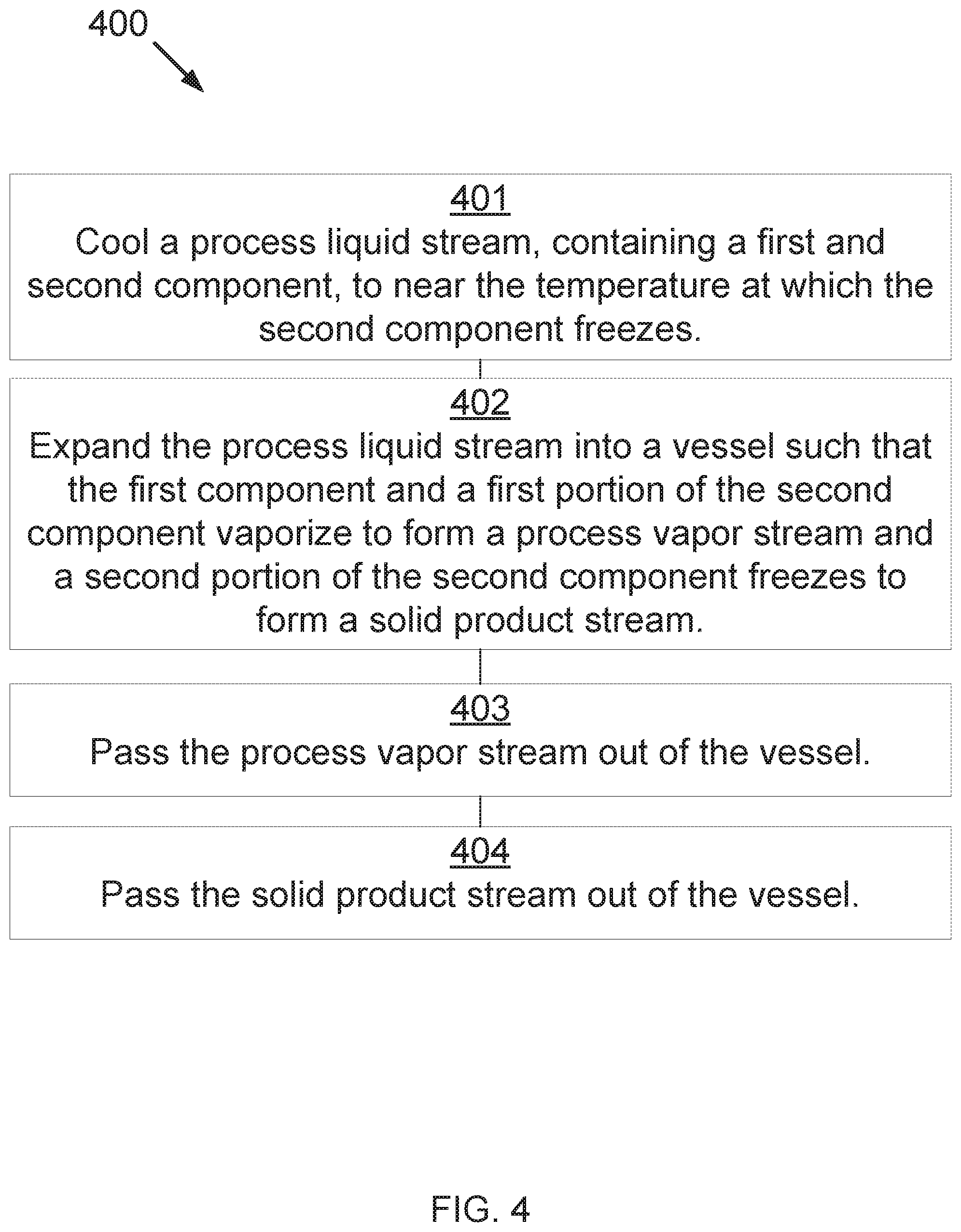
[0028] Now referring to FIG. 4, a block diagram showing a method 400 for separating components is disclosed as per one embodiment of the present invention. At 401, a process liquid stream, containing a first component and a second component, is cooled to near a temperature at which the second component forms a solid. At 402, the process liquid stream is expanded into a vessel such that the first component and a first portion of the second component vaporize to form a process vapor stream and a second portion of the second component forms a solid to form a solid product stream. At 403, the process vapor stream is passed out of the vessel. At 404, the solid product stream is passed out of the vessel.
[0029] Depending on conditions, some liquid may also form during expansion and either exit with the solid phase or as a separate stream.
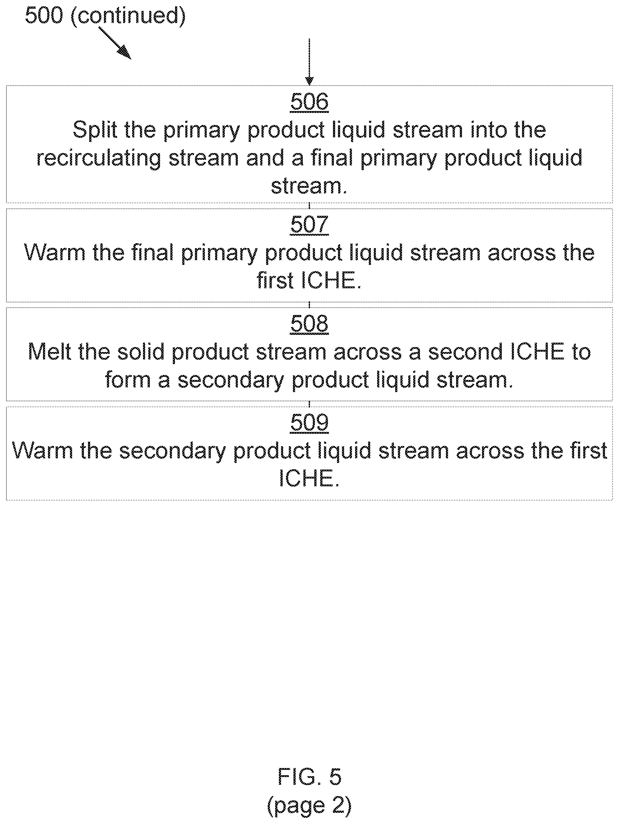
[0030] Now referring to FIG. 5, a block diagram showing a method 500 for separating components is disclosed as per one embodiment of the present invention. At 501, a supercritical process fluid stream is cooled across a first exchanger, producing a process liquid stream. The supercritical process fluid stream contains a first component and a second component. At 502, the process liquid stream and a recirculating stream are passed into a mixer to form a diluted process liquid stream near the temperature at which the second component forms a solid. The recirculating stream consists of the first component. At 503, the diluted process liquid stream is expanded into a vessel such that the first component and a first portion of the second component vaporize to form a process vapor stream and a second portion of the second component forms a solid to form a solid product stream. At 504, the solid product stream and the process vapor stream pass out of the vessel. At 505, the process vapor stream is compressed across a compressor and heat exchanger to form a primary product liquid stream. At 506, the primary product liquid stream is split into the recirculating stream and a final primary product liquid stream. Any non-condensable gases, such as N2, O2, and Argon, would be removed at this stage. At 507, the final primary product liquid stream is warmed across the first exchanger. At 508, the solid product stream is melted across a second exchanger to form a secondary product liquid stream. At 509, the secondary product liquid stream is warmed across the first exchanger.
[0031] In some embodiments, the first component consists of a hydrocarbon selected from the group consisting of methane, ethane, propane, isobutane, n-butane, C5 hydrocarbons, C6+ hydrocarbons, and combinations thereof. In some embodiments, the first component contains water. In some embodiments, the second component consists of an acid gas selected from the group consisting of carbon dioxide, sulfur oxides, nitrogen oxides, carbon monoxide, and combinations thereof.
[0032] In some embodiments, the vessel is selected from the group consisting of flash drum, an expansion chamber, a cyclone, and combinations thereof.
[0033] In some embodiments, when the process liquid stream is expanded into a vessel, a first portion of the first component and a first portion of the second component vaporize to form a process vapor stream, a second portion of the second component forms a solid to form a solid product stream, and a second portion of the first component and a third portion of the second component remain as a carrier liquid stream. The solid product stream is entrained in the carrier liquid stream, resulting in a slurry stream. The process vapor stream is passed out of the vessel and the slurry stream is passed out of the vessel. In some embodiments, the slurry stream is expanded into a second vessel. The first component in the carrier liquid stream vaporizes to form a second process vapor stream. The second component in the carrier liquid stream forms a second solid product stream. The second process vapor stream is passed out of the second vessel and the solid product stream and the second solid product stream are passed out of the second vessel.
[0034] The invention has been described with reference to various specific and preferred embodiments and techniques. Nevertheless, it is understood that many variations and modifications may be made while remaining within the spirit and scope of the invention.
* * * * *
D00000
D00001
D00002
D00003
D00004
D00005
D00006
XML
uspto.report is an independent third-party trademark research tool that is not affiliated, endorsed, or sponsored by the United States Patent and Trademark Office (USPTO) or any other governmental organization. The information provided by uspto.report is based on publicly available data at the time of writing and is intended for informational purposes only.
While we strive to provide accurate and up-to-date information, we do not guarantee the accuracy, completeness, reliability, or suitability of the information displayed on this site. The use of this site is at your own risk. Any reliance you place on such information is therefore strictly at your own risk.
All official trademark data, including owner information, should be verified by visiting the official USPTO website at www.uspto.gov. This site is not intended to replace professional legal advice and should not be used as a substitute for consulting with a legal professional who is knowledgeable about trademark law.