Fence Rail End Support System
Xuewei; Zhou ; et al.
U.S. patent application number 16/372533 was filed with the patent office on 2020-10-08 for fence rail end support system. This patent application is currently assigned to BODO Plastics Company LTD. The applicant listed for this patent is BODO Plastics Company LTD. Invention is credited to Sun Feng, Zhou Xuewei.
| Application Number | 20200318380 16/372533 |
| Document ID | / |
| Family ID | 1000004036176 |
| Filed Date | 2020-10-08 |


| United States Patent Application | 20200318380 |
| Kind Code | A1 |
| Xuewei; Zhou ; et al. | October 8, 2020 |
FENCE RAIL END SUPPORT SYSTEM
Abstract
A fence rail end support system includes a mounting plate having a plurality of mounting apertures wherein the mounting plate is configured for being attached to a fence post by fasteners extending through the mounting apertures. Each of a pair of support panels extends perpendicularly from the mounting plate wherein an end of a fence rail is positionable between the pair of support panels. Each of a plurality of connection slots extends through the pair of support panels to receive a connector to secure an associated one of the pair of support panels to the fence rail.
| Inventors: | Xuewei; Zhou; (Zibo City, CN) ; Feng; Sun; (Zibo City, CN) | ||||||||||
| Applicant: |
|
||||||||||
|---|---|---|---|---|---|---|---|---|---|---|---|
| Assignee: | BODO Plastics Company LTD Zibo City CN |
||||||||||
| Family ID: | 1000004036176 | ||||||||||
| Appl. No.: | 16/372533 | ||||||||||
| Filed: | April 2, 2019 |
| Current U.S. Class: | 1/1 |
| Current CPC Class: | E04H 17/1413 20130101; E04H 2017/1452 20130101 |
| International Class: | E04H 17/14 20060101 E04H017/14 |
Claims
1. A fence rail end support system comprising: a mounting plate having a back face and a front face, said back face being planar; a plurality of mounting apertures extending through said mounting plate wherein said mounting plate is configured for being attached to the fence post by fasteners extending through said mounting apertures; a fence rail having an end; a pair of support panels extending perpendicularly from said front face of said mounting plate wherein said end of said fence rail is positionable between said pair of support panels; and a plurality of connection slots extending through said pair of support panels wherein each of said connection slots is configured for receiving a connector to secure an associated one of said pair of support panels to said fence rail when said end of said fence rail is positioned between said pair of support panels.
2. The system of claim 1, further comprising said plurality of connection slots being arranged into horizontally aligned pairs, each connection slot of each of said aligned pairs being positioned extending through an associated one of said support panels.
3. The system of claim 2, further comprising said fence rail having elongated grooves extending inwardly from said end of said fence rail, each of said grooves aligning with a respective one of said connection slots when said end of said fence rail is inserted between said support panels.
4. The system of claim 1, further comprising: a fence panel, said fence panel having an elongated ridge extending along a lateral side of said fence panel, said fence panel having a top edge extending perpendicularly from a top end of said elongated ridge, said top edge being insertable into a bottom section of said fence rail wherein said elongated ridge extends laterally relative to said end of said fence rail; and a ridge slot extending into said mounting plate, said ridge slot extending into a bottom edge of said mounting plate, said ridge slot being centrally positioned between said support panels wherein an upper portion of said elongated ridge is seated in said ridge slot when said end of said fence rail is inserted between said support panels.
5. The system of claim 1, further comprising each of said support panels having a distal edge relative to said mounting plate, said distal edge of each said support panel having a vertical top section and a curved bottom section, said curved bottom section curving down and toward a middle of said mounting plate such that bottom edges of said pair of support plates are directed towards each other.
6. The system of claim 5, further comprising said vertical top sections of each of said distal edges being convex relative to said mounting plate.
7. The system of claim 1, further comprising a plurality of braces, said braces being distributed along respective base edges of said support panels on an outer side of said support panels.
8. The system of claim 7, further comprising said braces being arranged to define gaps between adjacently positioned braces, each of said gaps being laterally aligned with a respective one of said mounting apertures.
9. A fence rail end support system comprising: a mounting plate having a back face and a front face, said back face being planar; a plurality of mounting apertures extending through said mounting plate wherein said mounting plate is configured for being attached to the fence post by fasteners extending through said mounting apertures; a fence rail having an end, said fence rail having elongated grooves extending inwardly from said end of said fence rail; a pair of support panels extending perpendicularly from said front face of said mounting plate wherein said end of said fence rail is positionable between said pair of support panels; a plurality of connection slots extending through said pair of support panels wherein each of said connection slots is configured for receiving a connector to secure an associated one of said pair of support panels to said fence rail when said end of said fence rail is positioned between said pair of support panels, said plurality of connection slots being arranged into horizontally aligned pairs, each connection slot of each of said aligned pairs being positioned extending through an associated one of said support panels, each of said grooves aligning with a respective one of said connection slots when said end of said fence rail is inserted between said support panels; a fence panel, said fence panel having an elongated ridge extending along a lateral side of said fence panel, said fence panel having a top edge extending perpendicularly from a top end of said elongated ridge, said top edge being insertable into a bottom section of said fence rail wherein said elongated ridge extends laterally relative to said end of said fence rail; a ridge slot extending into said mounting plate, said ridge slot extending into a bottom edge of said mounting plate, said ridge slot being centrally positioned between said support panels wherein an upper portion of said elongated ridge is seated in said ridge slot when said end of said fence rail is inserted between said support panels; each of said support panels having a distal edge relative to said mounting plate, said distal edge of each said support panel having a vertical top section and a curved bottom section, said curved bottom section curving down and toward a middle of said mounting plate such that bottom edges of said pair of support plates are directed towards each other, said vertical top sections of each of said distal edges being convex relative to said mounting plate; and a plurality of braces, said braces being distributed along respective base edges of said support panels on an outer side of said support panels, said braces being arranged to define gaps between adjacently positioned braces, each of said gaps being laterally aligned with a respective one of said mounting apertures.
Description
CROSS-REFERENCE TO RELATED APPLICATIONS
[0001] Not Applicable
STATEMENT REGARDING FEDERALLY SPONSORED RESEARCH OR DEVELOPMENT
[0002] Not Applicable
THE NAMES OF THE PARTIES TO A JOINT RESEARCH AGREEMENT
[0003] Not Applicable
INCORPORATION-BY-REFERENCE OF MATERIAL SUBMITTED ON A COMPACT DISC OR AS A TEXT FILE VIA THE OFFICE ELECTRONIC FILING SYSTEM
[0004] Not Applicable
STATEMENT REGARDING PRIOR DISCLOSURES BY THE INVENTOR OR JOINT INVENTOR
[0005] Not Applicable
BACKGROUND OF THE INVENTION
(1) Field of the Invention
[0006] The disclosure relates to rail support devices and more particularly pertains to a new rail support device for facilitating connection of a fence rail to a fence post with a minimal gap between the fence post and an end of the fence rail.
(2) Description of Related Art Including Information Disclosed Under 37 CFR 1.97 and 1.98
[0007] The prior art relates to rail support devices.
BRIEF SUMMARY OF THE INVENTION
[0008] An embodiment of the disclosure meets the needs presented above by generally comprising a mounting plate having a plurality of mounting apertures wherein the mounting plate is configured for being attached to a fence post by fasteners extending through the mounting apertures. Each of a pair of support panels extends perpendicularly from the mounting plate wherein an end of a fence rail is positionable between the pair of support panels. Each of a plurality of connection slots extends through the pair of support panels to receive a connector to secure an associated one of the pair of support panels to the fence rail.
[0009] There has thus been outlined, rather broadly, the more important features of the disclosure in order that the detailed description thereof that follows may be better understood, and in order that the present contribution to the art may be better appreciated. There are additional features of the disclosure that will be described hereinafter and which will form the subject matter of the claims appended hereto.
[0010] The objects of the disclosure, along with the various features of novelty which characterize the disclosure, are pointed out with particularity in the claims annexed to and forming a part of this disclosure.
BRIEF DESCRIPTION OF SEVERAL VIEWS OF THE DRAWING(S)
[0011] The disclosure will be better understood and objects other than those set forth above will become apparent when consideration is given to the following detailed description thereof. Such description makes reference to the annexed drawings wherein:
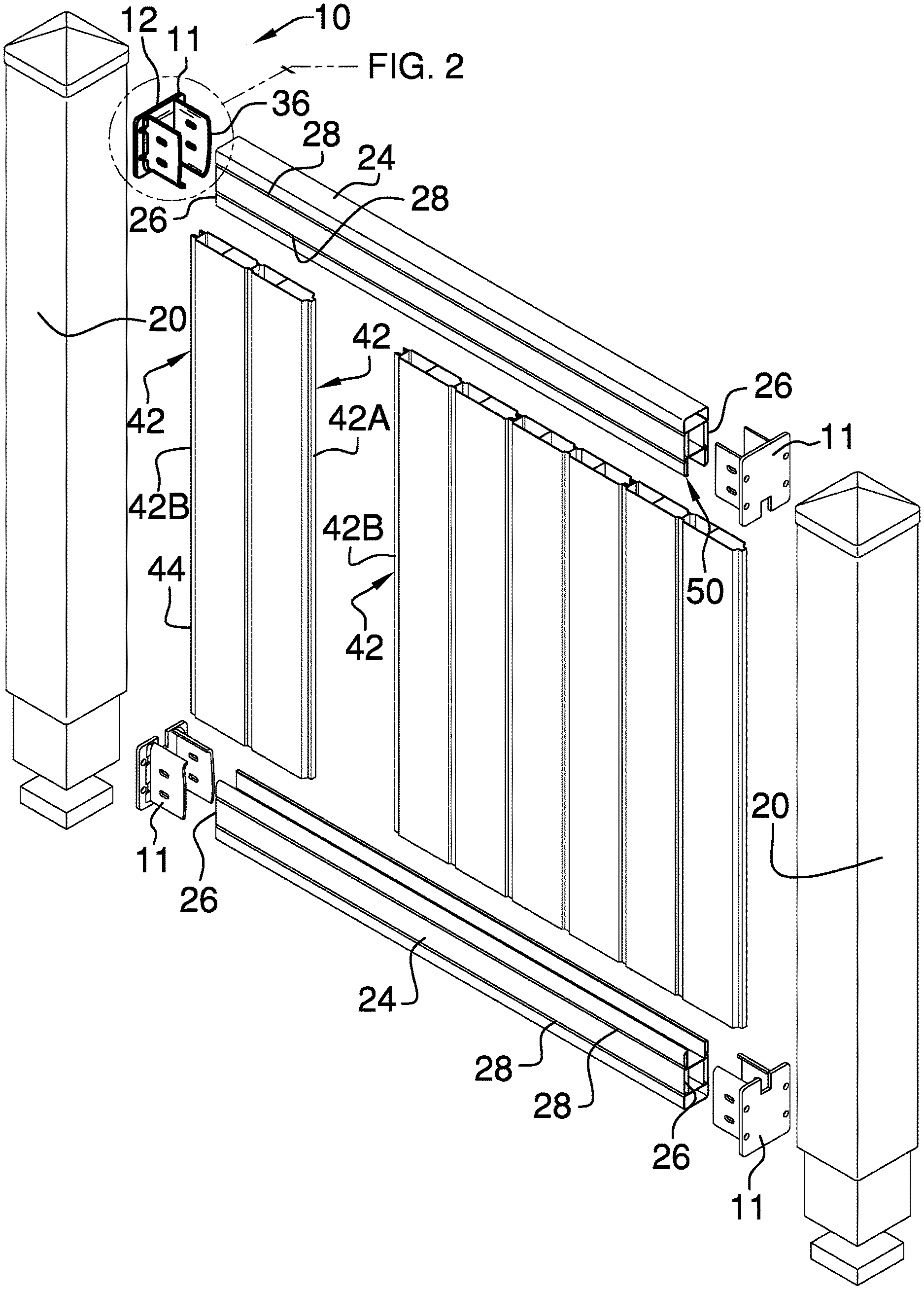
[0012] FIG. 1 is an exploded top front side perspective view of a fence rail end support system according to an embodiment of the disclosure.
[0013] FIG. 2 is a detailed view of an embodiment of the disclosure.
[0014] FIG. 3 is a side view of an end support of an embodiment of the disclosure.
[0015] FIG. 4 is a side view of an end support of an embodiment of the disclosure.
[0016] FIG. 5 is a front view of an end support of an embodiment of the disclosure.
[0017] FIG. 6 is a back view of an end support of an embodiment of the disclosure.
DETAILED DESCRIPTION OF THE INVENTION
[0018] With reference now to the drawings, and in particular to FIGS. 1 through 6 thereof, a new rail support device embodying the principles and concepts of an embodiment of the disclosure and generally designated by the reference numeral 10 will be described.
[0019] As best illustrated in FIGS. 1 through 6, the fence rail end support system 10 generally comprises an end support 11 having a mounting plate 12 and a pair of support panels 30. The mounting plate 12 has a back face 14 and a front face 16. The back face 14 is planar. Each of a plurality of mounting apertures 18 extends through the mounting plate 12 wherein the mounting plate 12 is configured for being attached to a fence post 20 by fasteners 22 extending through the mounting apertures 18. The fasteners 22 are conventional and may be screws or the like.
[0020] A fence rail 24 has an end 26. The fence rail 24 has elongated grooves 28 extending perpendicularly and inwardly from the end 26 of the fence rail 24. For functional purposes relating to connection each elongated groove 28 need only extend partially along the fence rail 24. However, for structural stiffness, facilitation of production, or aesthetics, each elongated groove 28 may extend a full length of the fence rail 24 as shown in FIG. 1.
[0021] Each of the pair of support panels 30 extends perpendicularly from the front face 14 of the mounting plate 12 wherein the end 26 of the fence rail 24 is positionable between the pair of support panels 30. Each of a plurality of connection slots 32 extends through the pair of support panels 30 wherein each of the connection slots 32 is configured for receiving a connector 34 to secure an associated one of the pair of support panels 30 to the fence rail 24 when the end 26 of the fence rail 24 is positioned between the pair of support panels 30 abutting or nearly abutting the mounting plate 12. The connection slots 32 are arranged into horizontally aligned pairs 36. Each connection slot 32 of each of the aligned pairs 36 is positioned extending through an associated one of the support panels 30. Each of the grooves 28 aligns with a respective one of the connection slots 32 when the end 26 of the fence rail 24 is inserted between the support panels 30.
[0022] A fence panel 40 has an elongated ridge 42 extending along a lateral side 44 of the fence panel 40. The fence panel 40 also has a top edge 46 extending perpendicularly from a top end 48 of the elongated ridge 42. The top edge 46 is insertable into a bottom section 50 of the fence rail 24 wherein the elongated ridge 42 extends outward laterally relative to the end 24 of the fence rail 24. A ridge slot 52 extends into the mounting plate 12. The ridge slot 52 extends into a bottom edge 54 of the mounting plate 12. The ridge slot 52 is centrally positioned between the support panels 30 wherein an upper portion 54 of the elongated ridge 42 is seated in the ridge slot 52 when the end 26 of the fence rail 24 is inserted between the support panels 30. The fence panel 40 is one of a plurality of fence panels 40 having respective elongated ridges 42 on of the lateral sides 44 of the fence panel 40. To allow for interconnection of the fence panels 40 the elongated ridges 42 on each fence panel 40 include a male variety 42A and a female variety 42B. However, for the purpose of engagement to oppositely positioned end supports 11, the specific variety of the elongated ridge 42 is not critical as both the male variety 42A and female variety 42B are considered to similarly position within the ridge slot 52. Thus, the elongated ridge 42 may abut or vary nearly abut the adjacently positioned fence post 20.
[0023] Each of the support panels 30 has a distal edge 56 relative to the mounting plate 12. The distal edge 56 of each support panel 30 has a vertical top section 58 and a curved bottom section 60. The curved bottom section 60 curves down and toward a middle of the mounting plate 12 such that bottom edges 62 of the pair of support plates 30 are directed towards each other. The shape of the curved bottom section 60 generally conforms to or complements a shape of the fence rail 24. The vertical top section 58 of each of the distal edges 56 is convex relative to the mounting plate 12.
[0024] Each of a plurality of braces 66 is distributed along respective base edges 68 of the support panels 30 on an outer side 70 of the support panels 30. The braces 66 are arranged to define gaps 72 between adjacently positioned braces 66. Each of the gaps 66 is laterally aligned with a respective one of the mounting apertures 18. Additionally, each of the gaps 66 aligns with an associated one of the connection slots 32 facilitating connections using the fasteners 22 and connectors 34.
[0025] In use, the end supports 11 are used to both connect to the fence rail 24 and to receive and position the elongated ridge 42 adjacent to the fence post 20. The structures as described above are provided to allow for 180 degree rotation and inversion to use the same end support structure for top left, bottom left, top right and bottom right connections as shown in FIG. 1.
[0026] With respect to the above description then, it is to be realized that the optimum dimensional relationships for the parts of an embodiment enabled by the disclosure, to include variations in size, materials, shape, form, function and manner of operation, assembly and use, are deemed readily apparent and obvious to one skilled in the art, and all equivalent relationships to those illustrated in the drawings and described in the specification are intended to be encompassed by an embodiment of the disclosure.
[0027] Therefore, the foregoing is considered as illustrative only of the principles of the disclosure. Further, since numerous modifications and changes will readily occur to those skilled in the art, it is not desired to limit the disclosure to the exact construction and operation shown and described, and accordingly, all suitable modifications and equivalents may be resorted to, falling within the scope of the disclosure. In this patent document, the word "comprising" is used in its non-limiting sense to mean that items following the word are included, but items not specifically mentioned are not excluded. A reference to an element by the indefinite article "a" does not exclude the possibility that more than one of the element is present, unless the context clearly requires that there be only one of the elements.
* * * * *
D00000
D00001
D00002
D00003
D00004
D00005
XML
uspto.report is an independent third-party trademark research tool that is not affiliated, endorsed, or sponsored by the United States Patent and Trademark Office (USPTO) or any other governmental organization. The information provided by uspto.report is based on publicly available data at the time of writing and is intended for informational purposes only.
While we strive to provide accurate and up-to-date information, we do not guarantee the accuracy, completeness, reliability, or suitability of the information displayed on this site. The use of this site is at your own risk. Any reliance you place on such information is therefore strictly at your own risk.
All official trademark data, including owner information, should be verified by visiting the official USPTO website at www.uspto.gov. This site is not intended to replace professional legal advice and should not be used as a substitute for consulting with a legal professional who is knowledgeable about trademark law.