Toilet Trap Water Blocking Device
Liu; Chien-Kuo
U.S. patent application number 16/907782 was filed with the patent office on 2020-10-08 for toilet trap water blocking device. The applicant listed for this patent is Chien-Kuo Liu. Invention is credited to Chien-Kuo Liu.
| Application Number | 20200318333 16/907782 |
| Document ID | / |
| Family ID | 1000004928002 |
| Filed Date | 2020-10-08 |


| United States Patent Application | 20200318333 |
| Kind Code | A1 |
| Liu; Chien-Kuo | October 8, 2020 |
TOILET TRAP WATER BLOCKING DEVICE
Abstract
The present invention is directed to a device and method for blocking the toilet trap of a toilet for cleaning and disinfecting purposes. The device includes an inflatable member having an opening; an elongated fluid conduit having a proximal end and a distal end, the proximal end of the fluid conduit is coupled to the opening of the inflatable member; a disc coupled between the opening of the inflatable member and the proximal end of the fluid conduit; and a pump assembly coupled to the distal end of the elongated fluid conduit, wherein the inflatable member, the elongated fluid conduit, and the pump assembly are in fluid communication, the pump assembly comprises a fluid pump for pumping fluid under pressure and a release valve for releasing the fluid under pressure.
| Inventors: | Liu; Chien-Kuo; (Honolulu, HI) | ||||||||||
| Applicant: |
|
||||||||||
|---|---|---|---|---|---|---|---|---|---|---|---|
| Family ID: | 1000004928002 | ||||||||||
| Appl. No.: | 16/907782 | ||||||||||
| Filed: | June 22, 2020 |
| Current U.S. Class: | 1/1 |
| Current CPC Class: | E03D 9/00 20130101 |
| International Class: | E03D 9/00 20060101 E03D009/00 |
Claims
1. A method of cleaning toilets, the method comprising: providing a device, the device comprising: an inflatable member having an opening; an elongated fluid conduit having a proximal end and a distal end, the proximal end of the fluid conduit is coupled to the opening of the inflatable member; a pump assembly coupled to the distal end of the elongated fluid conduit, wherein the inflatable member, the elongated fluid conduit, and the pump assembly are in fluid communication; positioning the device into a toilet bowl wherein the inflatable member is positioned into the toilet trap; and operating the pump assembly to inflate the inflatable member till the inflatable member snugly fits into the toilet trap blocking the passage of water.
2. The method of claim 1, wherein the device further comprises a disc coupled to the proximal end of the elongated fluid conduit.
3. The method of claim 1, wherein the pump assembly comprises a fluid pump and a release valve, the fluid pump configured to pump fluid under pressure, the release valve configured to release the fluid under pressure.
4. The method of claim 3, wherein the method further comprises the steps of: filling water into the toilet bowl up to a predetermined level; adding a cleansing agent to the water; and opening the release valve to deflate the inflatable member after a predetermined time.
5. The method of claim 4, wherein the inflatable member is of oval shape.
6. The method of claim 4, wherein the inflatable member is of round shape.
7. The method of claim 3, wherein the fluid pump is an electronic pump, and the pump assembly further comprises a battery for powering the electric pump.
8. The method of claim 3, wherein the fluid pump is a squeeze bulb, and the pump assembly further comprises a first check valve and a second check valve, the first check valve fluidly connects the squeeze bulb to the elongated fluid conduit, the first check valve configured to allow fluid to transfer from the squeeze bulb to the elongated fluid conduit, the second check valve fluidly connects the squeeze bulb to atmosphere and permits fluid from outside to be drawn into the squeeze bulb.
9. The method of claim 4, wherein the fluid is air.
10. The method of claim 1, wherein the elongated fluid conduit is rigid but could bend under an external force to conform to the shape of the toilet trap.
11. A device for blocking a toilet trap, the device comprising: an inflatable member having an opening; an elongated fluid conduit having a proximal end and a distal end, the proximal end of the elongated fluid conduit is coupled to the opening of the inflatable member; a disc coupled between the opening of the inflatable member and the proximal end of the fluid conduit; and a pump assembly coupled to the distal end of the elongated fluid conduit, wherein the inflatable member, the elongated fluid conduit, and the pump assembly are in fluid communication, the pump assembly comprises a fluid pump for pumping fluid under pressure and a release valve for releasing the fluid under pressure.
12. The device of claim 11, wherein the fluid pump is an electric fluid pump and the pump assembly further comprises a battery for powering the electric pump.
13. The device of claim 11, wherein the fluid pump is a squeeze bulb, and the pump assembly further comprises a first check valve and a second check valve, the first check valve fluidly connects the squeeze bulb to the fluid conduit, the first check valve configured to allow fluid to transfer from the squeeze bulb to the fluid conduit, the second check valve fluidly connects the squeeze bulb to outside atmosphere and permits fluid to be drawn into the squeeze bulb.
14. The device of claim 11, wherein the inflatable member is a round shaped balloon that is dimensioned to snugly fit into the toilet trap when inflated.
Description
FIELD OF INVENTION
[0001] The present invention relates an inflatable device and in more particular, the present invention relates to an inflatable device to assist in toilet cleaning.
BACKGROUND
[0002] Toilets often become dirty and acquire foul, unpleasant odors. No one enjoys cleaning toilets, especially ones that are caked with layers of waste, stains, and/or smell repulsive. No matter the extent of filth, it is necessary to clean and maintain a sanitary toilet. There are many toilet cleaning solutions and tools on the market, most of which require the use of a brush or similar tool to clean the toilet bowl. However, such a process of cleaning the toilets is inefficient, time-consuming, and laborious.
[0003] Toilet manufacturers designed toilets to maintain a low water level inside the base of the toilet. The lower curving channel inside the base of the toilet is commonly known as a toilet trap or trap way. This connects the toilet bowl to the drainage pipe. Depending upon the curvature of the toilet trap, the lower portion of the toilet trap always contains an amount of water. A cleaning solution of disinfectant can be added to the water in the toilet trap which keeps is clean. However, the upper portion of the toilet bowl is empty and dry, which results in water rings, urine stains, feces stains, and other contaminants that cause the toilet bowl to become dirty.
[0004] Thus, a need is appreciated for a device that allows water to be retained in the toilet bowl, above the limits of the toilet trap.
SUMMARY OF THE INVENTION
[0005] The principal objective of the present invention is therefore directed to a device that allows retaining water in a toilet bowl above the toilet trap's water level.
[0006] It is a further objective of the present invention that the device is economical to manufacture.
[0007] It is an additional objective of the present invention that the device can be easily deployed and removed from the toilet bowl.
[0008] It is still an additional objective of the present invention that the device allows the cleaning of the toilet bowl.
[0009] It is yet an additional objective of the present invention is that the device can be used hygienically.
[0010] It is another objective of the present invention that the device is compact for storage.
[0011] It is a further another object of the present invention that the device allows water to be retained in the toilet bowl up to desired levels.
[0012] It is yet another object of the present invention that the device allows water to be retained in the toilet bowl up to brim levels.
[0013] In one aspect, the present invention is directed to a device for temporarily blocking the toilet trap. The blocking of the toilet trap results in retaining water above the toilet trap's water level. The water can be filled into the toilet bowl up to desired levels. The device comprises an inflatable member having an opening; a fluid conduit for conveying fluid, the fluid conduit having a proximal end and a distal end. The conduit at the proximal end is in fluid communication with the opening of the inflatable member. The distal end of the fluid conduit is coupled to a pump assembly, wherein the inflatable member, the elongated fluid conduit, and the pump assembly are in fluid communication. The pump assembly comprises a fluid pump for pumping fluid under pressure and a release valve for releasing the fluid under pressure.
[0014] In one aspect, the fluid pump is an electric fluid pump and the pump assembly further comprises a battery for powering the electric pump.
[0015] In one aspect, the fluid pump is a squeeze bulb, and the pump assembly further comprises a first check valve and a second check valve, the first check valve fluidly connects the squeeze bulb to the fluid conduit, the first check valve configured to allow fluid to transfer from the squeeze bulb to the fluid conduit, the second check valve fluidly connects the squeeze bulb to the atmosphere and permits fluid from outside to be drawn into the squeeze bulb.
[0016] In one aspect, the present invention is directed to a method for blocking a toilet trap. The method comprising the steps of positioning the device into a toilet bowl wherein the inflatable member is positioned into the toilet trap. Thereafter, operating the pump assembly to inflate the inflatable member till the inflatable member snugly fits into the toilet trap blocking the passage of water. Once, the inflatable member blocks the toilet trap, water can be filled into the toilet bowl up to a predetermined level, for example, up to the brim of the toilet bowl. Thereafter, a cleansing agent can be added to the water. After a predetermined period, the release valve can be opened to deflate the inflatable member, resulting in draining of the water.
[0017] These and other objects and advantages of the embodiments herein will become readily apparent from the following detailed description.
BRIEF DESCRIPTION OF THE DRAWINGS
[0018] The accompanying figures, which are incorporated herein, form part of the specification and illustrate embodiments of the present invention. Together with the description, the figures further explain the principles of the present invention and to enable a person skilled in the relevant arts to make and use the invention.
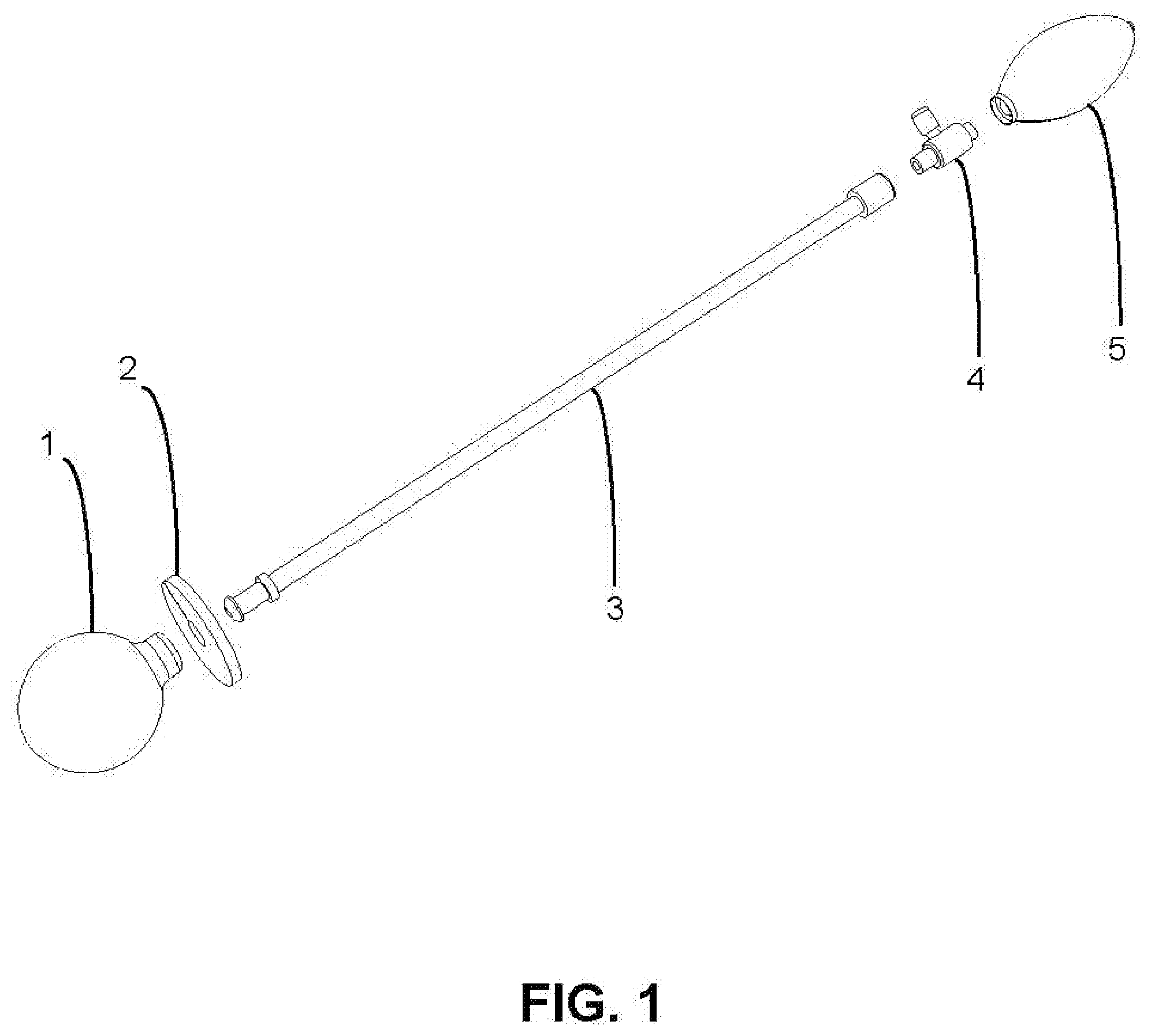
[0019] FIG. 1 is an exploded view of the device for blocking a toilet trap, according to an embodiment of the present invention.
[0020] FIG. 2 is a perspective view of the device, according to an exemplary embodiment of the present invention.
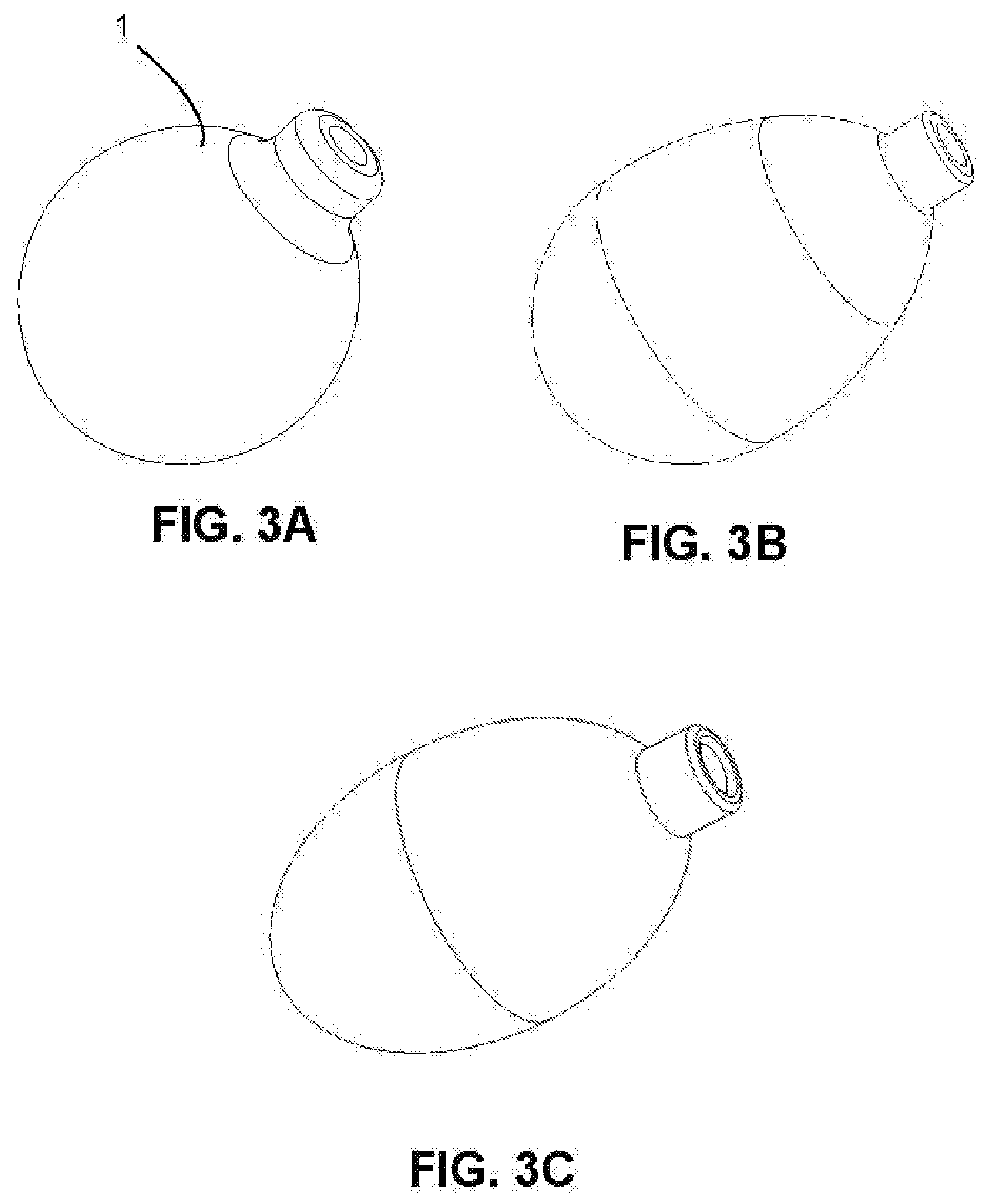
[0021] FIG. 3A shows a round shape inflatable member, according to an exemplary embodiment of the present invention.
[0022] FIG. 3B shows an oblong shape inflatable member, according to an exemplary embodiment of the present invention.
[0023] FIG. 3C shows an oval shape inflatable member, according to an exemplary embodiment of the present invention.
[0024] FIG. 4 is a perspective view of a disc, according to an exemplary embodiment of the present invention.
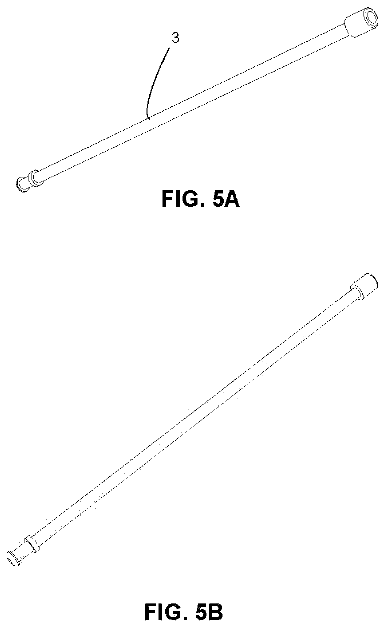
[0025] FIG. 5A is the perspective view of the fluid conduit, according to an exemplary embodiment of the present invention.
[0026] FIG. 5B is another perspective view of the fluid conduit, according to an exemplary embodiment of the present invention.
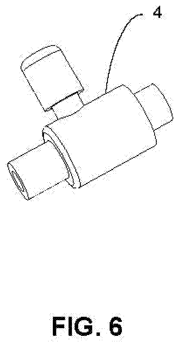
[0027] FIG. 6 shows a valve, according to an exemplary embodiment of the present invention.
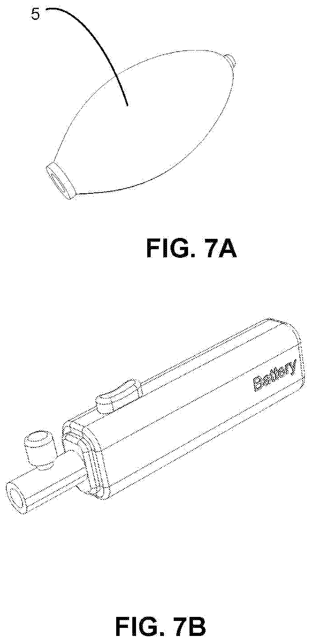
[0028] FIG. 7A shows a squeeze bulb, according to an exemplary embodiment of the present invention.
[0029] FIG. 7B shows an electric fluid pump, according to an exemplary embodiment of the present invention.
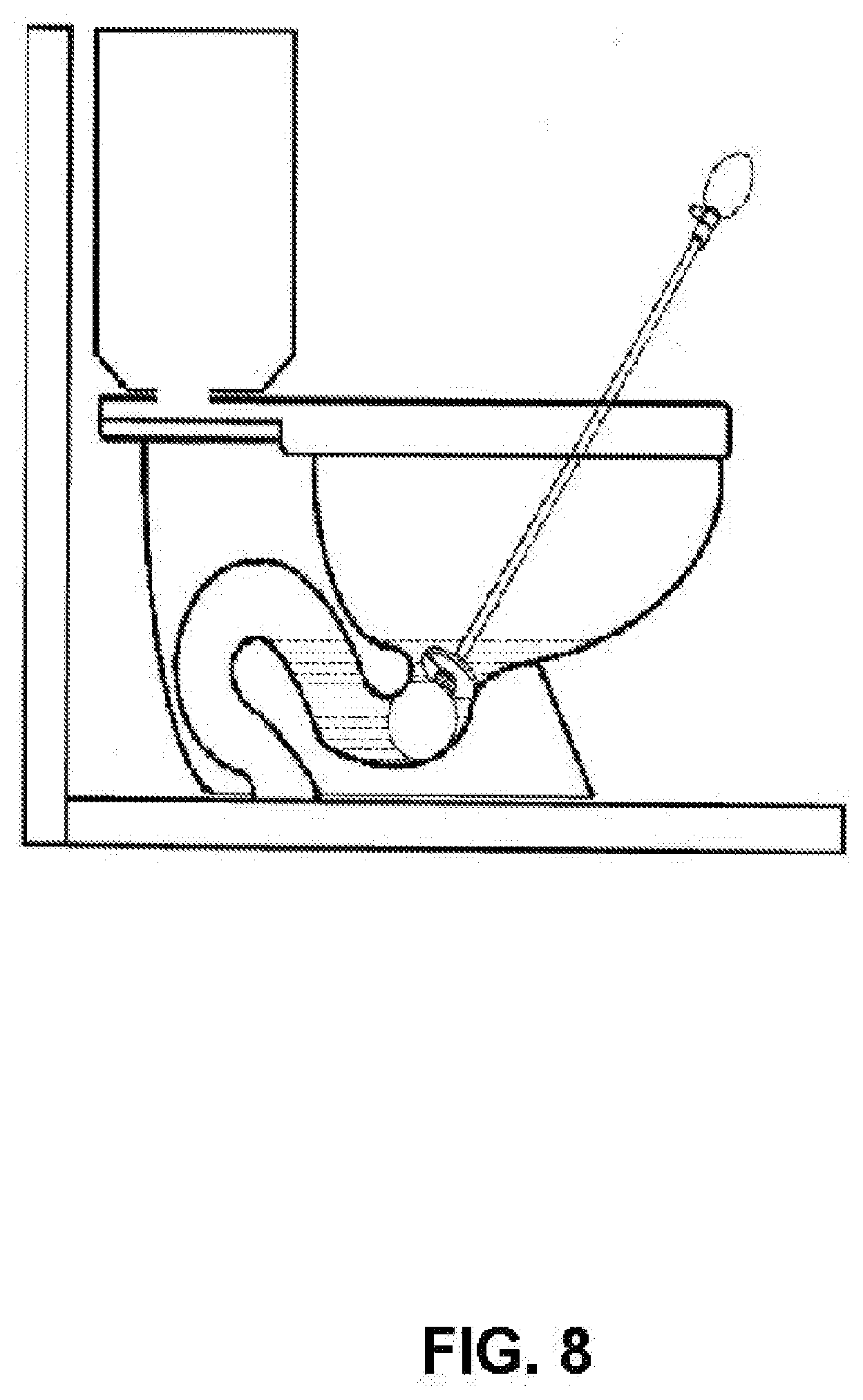
[0030] FIG. 8 shows the device positioned into the toilet trap, according to an exemplary embodiment of the present invention.
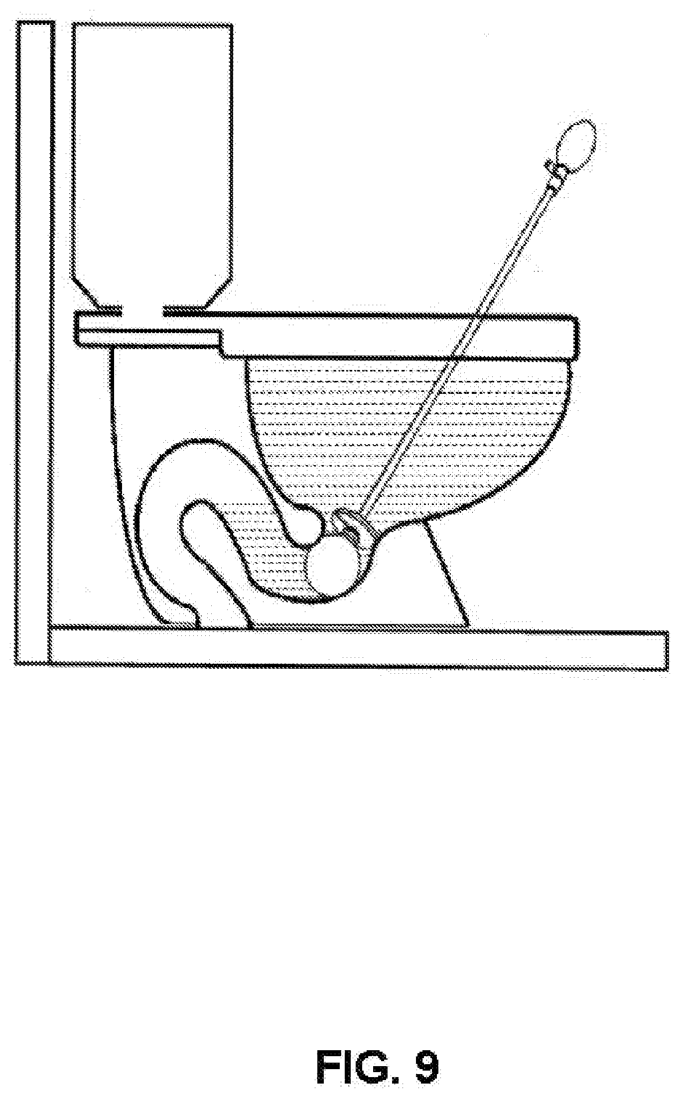
[0031] FIG. 9 shows the water retained up to brim level of the toilet bowl, according to an exemplary embodiment of the present invention.
DETAILED DESCRIPTION
[0032] Subject matter will now be described more fully hereinafter. Subject matter may, however, be embodied in a variety of different forms and, therefore, covered or claimed subject matter is intended to be construed as not being limited to any exemplary embodiments set forth herein; exemplary embodiments are provided merely to be illustrative. Likewise, a reasonably broad scope for claimed or covered subject matter is intended. Among other things, for example, the subject matter may be embodied as devices and methods of use thereof. The following detailed description is, therefore, not intended to be taken in a limiting sense.
[0033] The word "exemplary" is used herein to mean "serving as an example, instance, or illustration." Any embodiment described herein as "exemplary" is not necessarily to be construed as preferred or advantageous over other embodiments. Likewise, the term "embodiments of the present invention" does not require that all embodiments of the invention include the discussed feature, advantage, or mode of operation.
[0034] The terminology used herein is for the purpose of describing particular embodiments only and is not intended to be limiting of embodiments of the invention. As used herein, the singular forms "a", "an" and "the" are intended to include the plural forms as well, unless the context clearly indicates otherwise. It will be further understood that the terms "comprises", "comprising,", "includes" and/or "including", when used herein, specify the presence of stated features, integers, steps, operations, elements, and/or components, but do not preclude the presence or addition of one or more other features, integers, steps, operations, elements, components, and/or groups thereof.
[0035] The following detailed description includes the best currently contemplated mode or modes of carrying out exemplary embodiments of the invention. The description is not to be taken in a limiting sense but is made merely for the purpose of illustrating the general principles of the invention, since the scope of the invention will be best defined by the allowed claims of any resulting patent.
[0036] The following detailed description is described with reference to the drawings, wherein like reference numerals are used to refer to like elements throughout. In the following description, for purposes of explanation, specific details may be set forth in order to provide a thorough understanding of the subject innovation. It may be evident, however, that the claimed subject matter may be practiced without these specific details. In other instances, well-known structures and devices are shown in block diagram form in order to facilitate describing the subject innovation. Moreover, the drawings may not be to scale.
[0037] The present invention is directed to a device for blocking a toilet trap that allows water to be retained above the toilet trap's water level. Referring to FIGS. 1 and 2 which shows an exemplary embodiment of the device according to the present invention. The device is having an inflatable member 1, a disc 2, a fluid conduit 3, a valve assembly 4, and a squeeze bulb 5. The wall of the inflatable member 1 can be made of elastic material that can expand on inflation. Moreover, the wall of the inflatable member 1 can be made of durable material. Since the toilet trap is a cylindrical channel, the inflatable member 1 can also be provided in a round shape. FIG. 3A-3C shows exemplary embodiments of the inflatable member being a spherical balloon shape, an oblong shape, or an oval shape. Although FIG. 3A-3C shows exemplary shapes of the inflatable member 1, a skilled person will appreciate that the inflatable member 1 can be provided in any other shape provided that it can block the toilet trap preventing the passage of water. The dimension of the inflatable member 1 can be such that when inflated, it can snugly fit into the toilet trap, wherein the fluid inside the inflatable member 1 can exert enough pressure on the walls of the inflatable member 1 to effectively block the toilet trap. The inflatable member 1 has an opening for the drawing and releasing the fluid. The fluid can be air.
[0038] Now referring to FIG. 5A-5B which shows an exemplary embodiment of the fluid conduit 3. The fluid conduit 3 can be an elongated conduit for conveying fluid. The fluid can be air or liquid. The fluid conduit 3 can have a proximal end and a distal end. The fluid conduit 3 at the proximal end can be coupled to the opening of the inflatable member 1. The distal end of the fluid conduit 3 can be coupled to a pump assembly for inflating the inflatable member 1. In one implementation, the length of the fluid conduit 3 can be such as when the inflatable member 1 is positioned into the toilet trap, the other end, i.e. the distal end extends above the toilet bowl, as can be seen in FIG. 8. In one implementation, the fluid conduit 3 can be made of plastic or metal. Moreover, the fluid conduit 3 can be flexible enough to allow adjusting the position of the inflatable member into the toilet trap. However, the fluid conduit 3 is rigid enough for not getting bowed.
[0039] Pump assembly coupled to the distal end of the fluid conduit 3 delivers fluid under pressure into the inflatable member 1 for inflation. In one implementation, the pump assembly can be an electric fluid pump. In an alternate implementation, the pump assembly can be a manual fluid pump. An embodiment of the electric fluid pump is shown in FIG. 7B which includes an outlet port for fluidly connecting to the distal end of the fluid conduit 3. Above the port can be seen is a release valve that can be used to release the pressure inside the inflatable member i.e. releasing the fluid from the inflatable member. The functioning of the release valve is known in the art. For example, the release valve can be a screw-type release valve than can be unfastened to release the fluid under pressure. The functioning of the electric fluid pump is also known in the art. The pump assembly can include a battery for powering the electric fluid pump.
[0040] The mechanical pump assembly can comprise a first valve, a second valve, a release valve, and a squeeze bulb 5. The first valve 4 is shown in FIG. 6 having an inlet and an outlet. The first valve can be a one-way valve that allows fluid to be transferred from inlet to outlet. The outlet can be coupled to the fluid conduit 3, while the inlet can be coupled to the squeeze bulb. Adjacent the outlet of the first valve can be configured a release valve for releasing the fluid under pressure from the inflatable member resulting in its deflation. An embodiment of the squeeze bulb is shown in FIG. 7A. The squeeze bulb is having an elongated resilient construction that is domed-shaped and provided with an opening that can be coupled to the first valve. The squeeze bulb can be collapsed under applied finger pressure, wherein the volume of fluid evacuates the fluid chamber under the applied pressure and transfers through the first valve into the inflatable member. Between the squeeze bulb and the first valve, the second valve can be configured, which is also a one-way valve. The second valve can be configured to allow drawing the fluid from the atmosphere into the squeeze bulb. When the applied finger pressure is released, the squeeze bulb starts to expand radially outward and returns to its original relaxed shape, resulting in the generation of air pressure within the squeeze bulb that is lower than the external ambient air pressure. The low air pressure, consequently, results in the opening of the second valve, and a volume of the fluid is drawn into the squeeze bulb. The walls of the squeeze bulb can be made of any resilient material known to a skilled person used in the manufacturing of resilient bulbs. For example, rubber is known to have good resilient properties and can be used in the manufacture of the squeeze bulb of the present invention. Alternatively, resilient plastic material can also be used. Optionally, the walls of the squeeze bulb can be reinforced with lateral ribs that also enhance gripping of the squeeze bulb.
[0041] FIG. 8 shows the device deployed into the toilet bowl, wherein the inflatable member is shown to be positioned into the toilet trap. The fluid pump assembly extends above the toilet bowl. The inflatable member can be inflated by pumping air till the inflatable member snugly fits into the toilet trap. Thereafter water can be filled into the toilet bowl up to desired level. FIG. 9 shows water filled into the toilet bowl up to the brim level. Once, the toilet bowl is filled up to the desired level, a cleaning or disinfecting agent can be added to the water. Alternatively, the cleaning or disinfecting agent can be added first, and then the water can be filled. The cleaning or disinfecting agent can also be added while the water is being filled into the toilet bowl. For example, bleach can be added for both cleaning and disinfecting the toilet bowl.
[0042] To drain the water, the inflatable member can be deflated by opening the release valve. As the inflatable member starts deflating, the block is removed and the water in the toilet bowl drains out. The device can be taken out and stored. The disc as shown in FIG. 4 is coupled between the opening of the inflatable member and the fluid conduit. The round shape disc decreases any splashing in the toilet bowl caused by deflation of the inflatable member and rushing for the water into the drainage pipe.
[0043] The present invention is a device and a method of use thereof, that allows users to clean toilets without needing a brush to scrub during the cleaning process. A user can add their desired cleaning solutions once the water level has covered all the dirty parts within the toilet bowl. The cleaning solution will then have a greater efficiency rate within the toilet bowl as it will be able to come in contact with everything that needs to be cleaned. The interior of the toilet bowl will have a finished clean look once the water is drained and flushed away. This device and method will save time and energy of the user since the cleaning process does not require the hassle of a brush and/or direct contact. The present method is hygienic comparing with the average cleaning process that uses a brush. The brush accumulates bits of waste from the toilet bowl as it scrubs, which is unsanitary and a hassle for the user. The components of the device including the inflatable member, the disc, and the fluid conduit can have a smooth surface avoiding sticking of any contaminants. The device can be easily cleaned by placing the device under running water.
[0044] While the foregoing written description of the invention enables one of ordinary skill to make and use what is considered presently to be the best mode thereof, those of ordinary skill will understand and appreciate the existence of variations, combinations, and equivalents of the specific embodiment, method, and examples herein. The invention should therefore not be limited by the above-described embodiment, method, and examples, but by all embodiments and methods within the scope and spirit of the invention as claimed.
* * * * *
D00000
D00001
D00002
D00003
D00004
D00005
D00006
D00007
D00008
D00009
XML
uspto.report is an independent third-party trademark research tool that is not affiliated, endorsed, or sponsored by the United States Patent and Trademark Office (USPTO) or any other governmental organization. The information provided by uspto.report is based on publicly available data at the time of writing and is intended for informational purposes only.
While we strive to provide accurate and up-to-date information, we do not guarantee the accuracy, completeness, reliability, or suitability of the information displayed on this site. The use of this site is at your own risk. Any reliance you place on such information is therefore strictly at your own risk.
All official trademark data, including owner information, should be verified by visiting the official USPTO website at www.uspto.gov. This site is not intended to replace professional legal advice and should not be used as a substitute for consulting with a legal professional who is knowledgeable about trademark law.