Assembly Constituting An Acoustically Absorbent Material
Ravise; Florian ; et al.
U.S. patent application number 16/828302 was filed with the patent office on 2020-10-08 for assembly constituting an acoustically absorbent material. The applicant listed for this patent is Airbus Operations (S.A.S.). Invention is credited to Florent Mercat, Florian Ravise.
| Application Number | 20200316900 16/828302 |
| Document ID | / |
| Family ID | 1000004778521 |
| Filed Date | 2020-10-08 |

| United States Patent Application | 20200316900 |
| Kind Code | A1 |
| Ravise; Florian ; et al. | October 8, 2020 |
ASSEMBLY CONSTITUTING AN ACOUSTICALLY ABSORBENT MATERIAL
Abstract
An assembly constituting an acoustically absorbent material and including a first panel, a second panel pierced with holes, an intermediate panel pierced with through-holes and arranged between the first panel and the second panel, a first structure between the first panel and the intermediate panel and including first cages, a second structure between the second panel and the intermediate panel and including second cages, and for each through-hole of the intermediate panel, a tube opening out at the two ends thereof, where one of the ends of the tube is fixed to the intermediate panel at the through-hole, and where the other end of the tube is accommodated inside a first cage. Such an assembly makes it possible to obtain broad-band attenuation and is easy to manufacture.
| Inventors: | Ravise; Florian; (Saint-Herblain, FR) ; Mercat; Florent; (Toulouse, FR) | ||||||||||
| Applicant: |
|
||||||||||
|---|---|---|---|---|---|---|---|---|---|---|---|
| Family ID: | 1000004778521 | ||||||||||
| Appl. No.: | 16/828302 | ||||||||||
| Filed: | March 24, 2020 |
| Current U.S. Class: | 1/1 |
| Current CPC Class: | B32B 3/12 20130101; G10K 11/168 20130101; G10K 2210/107 20130101; B32B 2307/102 20130101; G10K 2210/1281 20130101 |
| International Class: | B32B 3/12 20060101 B32B003/12; G10K 11/168 20060101 G10K011/168 |
Foreign Application Data
| Date | Code | Application Number |
|---|---|---|
| Apr 2, 2019 | FR | 1903515 |
Claims
1. An assembly constituting an acoustically absorbent material and comprising: a first panel; a second panel pierced with holes; an intermediate panel pierced with through-holes and arranged between the first panel and the second panel; a first honeycomb structure extending between the first panel and the intermediate panel and comprising first cages; a second honeycomb structure extending between the second panel and the intermediate panel and comprising second cages; and for the intermediate panel, and for each through-hole of the intermediate panel, a tube opening out at two ends thereof, where one of the ends of the tube is fixed to the intermediate panel at the through-hole, and where another end of the tube is inside a first cage.
2. The assembly according to claim 1, wherein at least two tubes have different lengths.
3. The assembly according to claim 2, wherein the intermediate panel, the second panel and the tubes comprise acoustically rigid materials.
4. The assembly according to claim 1, wherein the intermediate panel, the second panel and the tubes comprise acoustically rigid materials.
Description
CROSS-REFERENCE TO RELATED APPLICATION
[0001] This application claims priority to French patent application number 19 03515 filed on Apr. 2, 2019, the entire disclosure of which is incorporated by reference herein.
TECHNICAL FIELD
[0002] The disclosure herein relates to an assembly constituting an acoustically absorbent material.
BACKGROUND
[0003] During operation, an aircraft engine generates noise. This engine is accommodated in a nacelle and, with a view to attenuating this noise, it is known to install assemblies constituting an acoustically absorbent material around the engine in the structure of the nacelle.
[0004] Such assemblies constituting an acoustically absorbent material have, for example, the form of honeycomb structures. Such a honeycomb structure comprises two parallel panels, one of which is perforated, and between which are arranged hexagonal cells juxtaposed relative to one another.
[0005] It is also known, in other applications, to use truncated cones that are placed in cavities.
[0006] Although, from an acoustic standpoint, such assemblies offer satisfactory results, it is desirable to seek an assembly constituting an acoustically absorbent material that makes it possible to attenuate a plurality of acoustic frequencies and that is easy to manufacture.
SUMMARY
[0007] An object of the subject matter herein is to disclose an assembly constituting an acoustically absorbent material that is able to attenuate a plurality of acoustic frequencies and that is easy to manufacture.
[0008] To that end, an assembly is disclosed constituting an acoustically absorbent material and comprising: [0009] a first panel; [0010] a second panel pierced with holes; [0011] an intermediate panel pierced with through-holes and arranged between the first panel and the second panel; [0012] a first honeycomb structure extending between the first panel and the intermediate panel and comprising first cages; [0013] a second honeycomb structure extending between the second panel and the intermediate panel and comprising second cages; and [0014] for the intermediate panel, and for each through-hole of the intermediate panel, a tube opening out at the two ends thereof, where one of the ends of the tube is fixed to the intermediate panel at the through-hole, and where the other end of the tube is accommodated inside a first cage.
[0015] Such an assembly makes it possible to obtain broad-band attenuation and is easy to manufacture.
[0016] Advantageously, at least two tubes have different lengths.
[0017] Advantageously, the intermediate panel, the second panel and the tubes are produced from acoustically rigid materials.
BRIEF DESCRIPTION OF THE DRAWING
[0018] The above-mentioned features of the disclosure herein, and also others, will become more clearly apparent upon reading the following description of an example embodiment, the description being given in relation to the appended drawing, in which
[0019] Figure (FIG.) 1 is a sectional, expanded view of an assembly constituting an acoustically absorbent material according to the disclosure herein.
DETAILED DESCRIPTION
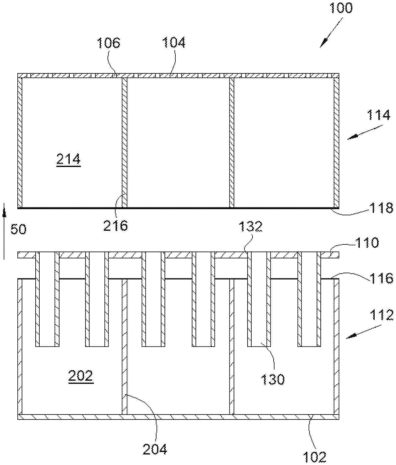
[0020] FIG. 1 shows an assembly 100 constituting an acoustically absorbent material according to the disclosure herein. The assembly 100 comprises a first panel 102 and a second panel 104 that are at a distance from one another. One of the panels, in this case the second panel 104, is pierced with holes 106 that traverse the panel in order to allow the passage of acoustic waves.
[0021] An intermediate panel 110 is arranged between the first panel 102 and the second panel 104. The three panels 102, 104 and 110 are parallel.
[0022] A first honeycomb structure 112 extends between the first panel 102 and the intermediate panel 110 and a second honeycomb structure 114 extends between the second panel 104 and the intermediate panel 110.
[0023] Thus, according to a stacking direction 50, the assembly 100 comprises, in succession, the first panel 102, the first honeycomb structure 112, the intermediate panel 110, the second honeycomb structure 114 and the second panel 104.
[0024] The first structure 112 comprises a succession of first cages 202, where each first cage 202 is hollow and is delimited by walls 204 extending in planes parallel to the stacking direction 50. In a preferred manner, each first cage 202 delimits a hexagonal cell, but other forms may be envisioned.
[0025] Similarly, the second structure 114 comprises a succession of second cages 214, where each second cage 214 is hollow and is delimited or defined by walls 216 extending in planes parallel to the stacking direction 50. In a preferred manner, each second cage 214 delimits or defines a hexagonal cell, but other forms may be envisioned.
[0026] The first panel 102 and the first structure 112 are fixed to one another, for example by adhesive bonding, welding, etc.
[0027] The second panel 104 and the second structure 114 are fixed to one another, for example by adhesive bonding, welding etc.
[0028] The first structure 112 and the intermediate panel 110 are fixed to one another, for example by adhesive bonding, welding, etc. The reference 116 shows a cross-linked adhesive sheet.
[0029] The second structure 114 and the intermediate panel 110 are fixed to one another, for example by adhesive bonding, welding, etc. The reference 118 shows a cross-linked adhesive sheet.
[0030] The second structure 114 with the second panel 104 and the intermediate panel 110 form a quarter-wave resonator that attenuates the acoustic high frequencies. The assembly 100 thus makes it possible to obtain broad-band attenuation and is easy to manufacture.
[0031] The assembly 100 also comprises, for each first cage 202, at least one tube 130 opening out at the two ends thereof and extending in a direction parallel to the stacking direction 50.
[0032] One of the ends of each tube 130 is fixed to the intermediate panel 110 at a through-hole 132 that the panel has for this purpose and that traverses the panel. There is thus a fluidic continuity between a second cage 214 and a first cage 202 via the tube 130. The tubes 130 are fixed to the intermediate panel 110, for example by welding, adhesive bonding, etc.
[0033] The other end of each tube 130 is accommodated inside the first cage 202 and opens out therein.
[0034] The first structure 112, with the first panel 102, the intermediate panel 110 and the tubes 130 form a Helmholtz resonator that attenuates the acoustic low frequencies. The frequency that is attenuated within the first structure 112 depends, inter alia, on the number of tubes 130 per first cage 202, on the diameter of the tubes 130 and on the length of the tubes 130.
[0035] Thus, in order to attenuate a broader frequency spectrum, the lengths of the tubes 130 are different from a first cage 202 to another. That is to say that at least two tubes 130 have different lengths.
[0036] According to an embodiment, the inside diameter of each tube is between 0.5 mm and 3 mm and the length of the tubes 130 may vary between 10 and 25 mm, for example. In the case of an aircraft engine and according to a particular embodiment, the second panel 104 is pierced with a level of perforations of the order of 6 to 8% in the case of an air intake and of the order of 13 to 15% in the case of a thrust reverser.
[0037] The various elements constituting the assembly 100 may be produced from different materials such as, for example, metallic materials such as aluminium or an aluminium alloy, or composite materials. The method for fixing the elements together will likewise depend on the materials used.
[0038] The intermediate panel 110, the second panel 104 and the tubes 130 are produced from acoustically rigid materials, i.e. they do not deform through the effect of the acoustic waves. On the other hand, the intermediate panel 110, the second panel 104 and the tubes 130 are produced from mechanically deformable or flexible materials so that it is possible to apply them over double curves.
[0039] According to an embodiment, the height of the second structure 114 is of the order of 25 mm in order to attenuate frequencies of interest within the context of an aircraft engine and the height of the first structure 112 is of the order of 15 mm. [0040] A method for manufacturing the assembly 100 is simple and comprises: a first supply step, during which the intermediate panel 110 with the through-holes 132 and the tubes 130 are provided; [0041] a first assembly step during which a tube 130 is fixed to the intermediate panel 110 at each through-hole 132; [0042] a second supply step during which the first panel 102 and the first structure 112 thus assembled are supplied; [0043] a second assembly step during which the intermediate panel 110 is fixed to the first structure 112; [0044] a third supply step during which the second panel 104 and the second structure 114 thus assembled are supplied; [0045] a fourth assembly step during which the intermediate panel 110 is fixed to the second structure 114.
[0046] Where the second structure 114 is adhesively bonded to the intermediate panel; the cross-linked adhesive sheet is not present at the through-holes 132 in order to prevent blocking of the tubes 130.
[0047] While at least one example embodiment of the invention(s) is disclosed herein, it should be understood that modifications, substitutions and alternatives may be apparent to one of ordinary skill in the art and can be made without departing from the scope of this disclosure. This disclosure is intended to cover any adaptations or variations of the example embodiment(s). In addition, in this disclosure, the terms "comprise" or "comprising" do not exclude other elements or steps, the terms "a", "an" or "one" do not exclude a plural number, and the term "or" means either or both. Furthermore, characteristics or steps which have been described may also be used in combination with other characteristics or steps and in any order unless the disclosure or context suggests otherwise. This disclosure hereby incorporates by reference the complete disclosure of any patent or application from which it claims benefit or priority.
* * * * *
D00000
D00001
XML
uspto.report is an independent third-party trademark research tool that is not affiliated, endorsed, or sponsored by the United States Patent and Trademark Office (USPTO) or any other governmental organization. The information provided by uspto.report is based on publicly available data at the time of writing and is intended for informational purposes only.
While we strive to provide accurate and up-to-date information, we do not guarantee the accuracy, completeness, reliability, or suitability of the information displayed on this site. The use of this site is at your own risk. Any reliance you place on such information is therefore strictly at your own risk.
All official trademark data, including owner information, should be verified by visiting the official USPTO website at www.uspto.gov. This site is not intended to replace professional legal advice and should not be used as a substitute for consulting with a legal professional who is knowledgeable about trademark law.