Pressing Machine And Corresponding Side Plate Unit Structure
HE; Biao ; et al.
U.S. patent application number 16/095688 was filed with the patent office on 2020-10-08 for pressing machine and corresponding side plate unit structure. The applicant listed for this patent is Wei CHEN, Biao HE, TongFei JIANG, FengChao SHEN, HaiJun WANG, WeiLi WANG, ChaoFeng ZHANG, JiaJia ZHU. Invention is credited to Wei CHEN, Biao HE, TongFei JIANG, FengChao SHEN, HaiJun WANG, WeiLi WANG, ChaoFeng ZHANG, JiaJia ZHU.
| Application Number | 20200316893 16/095688 |
| Document ID | / |
| Family ID | 1000004927981 |
| Filed Date | 2020-10-08 |


| United States Patent Application | 20200316893 |
| Kind Code | A1 |
| HE; Biao ; et al. | October 8, 2020 |
PRESSING MACHINE AND CORRESPONDING SIDE PLATE UNIT STRUCTURE
Abstract
A pressing machine comprising a base, wherein a first inner edge side plate and a second outer edge side plate are arranged on the base; a clamping chamber with sealed inner and outer end surfaces is reserved between the outer wall of the first inner edge side plate and the inner wall of the of the second outer edge side plate; the interior of the clamping chamber is used for preparing sandwich panels; the first inner edge side plate comprises a first side plate assembly, a second side plate assembly, a third side plate assembly and a fourth side plate assembly, wherein the four groups of the side plate assemblies are arranged in parallel in pairs; each side plate assembly is formed by assembling a plurality of side plate units along the length direction of the corresponding side plate assembly.
| Inventors: | HE; Biao; (Suzhou, CN) ; CHEN; Wei; (Suzhou, CN) ; ZHANG; ChaoFeng; (Suzhou, CN) ; SHEN; FengChao; (Suzhou, CN) ; JIANG; TongFei; (Suzhou, CN) ; ZHU; JiaJia; (Suzhou, CN) ; WANG; WeiLi; (Suzhou, CN) ; WANG; HaiJun; (Suzhou, CN) | ||||||||||
| Applicant: |
|
||||||||||
|---|---|---|---|---|---|---|---|---|---|---|---|
| Family ID: | 1000004927981 | ||||||||||
| Appl. No.: | 16/095688 | ||||||||||
| Filed: | July 7, 2017 | ||||||||||
| PCT Filed: | July 7, 2017 | ||||||||||
| PCT NO: | PCT/CN2017/092154 | ||||||||||
| 371 Date: | October 22, 2018 |
| Current U.S. Class: | 1/1 |
| Current CPC Class: | B30B 1/42 20130101; B32B 37/10 20130101; B32B 37/06 20130101; B30B 15/34 20130101; B30B 15/064 20130101 |
| International Class: | B30B 1/42 20060101 B30B001/42; B30B 15/06 20060101 B30B015/06; B30B 15/34 20060101 B30B015/34; B32B 37/06 20060101 B32B037/06; B32B 37/10 20060101 B32B037/10 |
Foreign Application Data
| Date | Code | Application Number |
|---|---|---|
| May 24, 2017 | CN | 201710371993.7 |
Claims
1. A pressing machine, comprising: a base, wherein a first inner edge side plate and a second outer edge side plate are arranged on the base, wherein a clamping chamber with sealed inner and outer end surfaces is reserved between the outer wall of the first inner edge side plate and the inner wall of the of the second outer edge side plate, wherein the interior of the clamping chamber is used for preparing sandwich panels, wherein the first inner edge side plate comprises a first side plate assembly, a second side plate assembly, a third side plate assembly and a fourth side plate assembly, wherein the four groups of the side plate assemblies are arranged in parallel in pairs, wherein each side plate assembly is formed by assembling a plurality of side plate units along the length direction of the corresponding side plate assembly, wherein each side plate unit comprises a heating module, an electromagnetic module and an insulating isolation module, wherein the insulating isolation module is located between the heating module and the electromagnetic module, wherein the heating modules that are located between the adjacent side plate units are connected with each other, and the electromagnetic modules that are located between the adjacent side plate units are connected with each other.
2. The pressing machine of claim 1, wherein a positioning threaded structure that protrudes inwards is arranged on the inner wall of the side plate unit, and a positioning threaded column is arranged on the base and corresponds to the positioning threaded structure, wherein the bottom of a square column is in threaded connection with the positioning threaded column, and a threaded through-hole is formed in the positioning threaded column that corresponds to the square column, wherein a bolt is in threaded connection with the corresponding threaded through-hole and the positioning threaded column.
3. The pressing machine of claim 2, wherein two positioning threaded columns that protrude inwards are arranged up and down on the inner wall of each side plate unit, thereby enabling the side plate units to be stably positioned.
4. The pressing machine of claim 3, wherein the two ends of each side plate assembly are respectively provided with a corner side plate unit, and the outer end of each corner side plate unit is cut off by 45 degrees, wherein the adjacent side plate assemblies are connected through assembling corresponding corner side plate units.
5. The pressing machine of claim 4, wherein a connecting square column that is fixed on the base and corresponds to the corner side plate unit is provided with two vertical-direction threaded through-holes, wherein a first bolt and a second bolt are respectively in threaded connection with the corresponding threaded through-holes and the positioning threaded structures that correspond to the corner side plate unit.
6. A side plate unit structure, comprising: a heating module, an electromagnetic module, and an insulating isolation module, wherein the insulating isolation module is located between the heating module and the electromagnetic module, wherein the heating module comprises a heating coil, a heating coil slotted plate and a heating layer cover, wherein a heating coil slot is formed in the heating coil slotted plate, and the heating coil is arranged in the heating coil slot, wherein the heating layer cover covers the outer end surface of the heating coil slotted plate, wherein the insulating isolation module is an electromagnetic isolation plate, wherein the electromagnetic module comprises electromagnetic coils, an electromagnetic coil slotted plate and an electromagnetic layer cover, wherein a plurality of electromagnetic coil slots is formed in the electromagnetic coil slotted plate, and the electromagnetic coils are embedded in the corresponding electromagnetic coil slots, wherein the adjacent electromagnetic coils are connected in series, and the electromagnetic layer cover covers the outer end surface of the electromagnetic coil slotted plate, wherein the two end surfaces of the electromagnetic isolation plate are respectively bonded with the inner end surface of the heating coil slotted plate and the inner end surface of the electromagnetic coil slotted plate.
7. The side plate unit structure of claim 6, wherein heating coil outward-extending slots that respectively face the adjacent side plate units are formed in the heating coil slotted plate, wherein the match line of the heating coil is connected with the heating coil of the adjacent side plate unit through the corresponding heating coil outward-extending slot.
8. The side plate unit structure of claim 6, wherein an electromagnetic coil inward-extending slot that is located between the adjacent electromagnetic coils of the same side plate unit is formed in the electromagnetic coil slotted plate, wherein the adjacent electromagnetic coils in the same side plate unit are connected in series through the conductors located between the corresponding electromagnetic coil inward-extending slots, wherein the electromagnetic coil slot formed in one end of the electromagnetic coil slotted plate is provided with an electromagnetic coil outward-extending slot that faces the adjacent side plate unit on one side, wherein the electromagnetic coil slot formed in the other end of the electromagnetic coil slotted plate is provided with an electromagnetic coil outward-extending slot that faces the adjacent side plate unit on the other side, wherein the electromagnetic coils that are connected in series with the adjacent side plate units through the conductors are placed into the two electromagnetic coil outward-extending slots.
9. The side plate unit structure of claim 6, wherein the electromagnetic module is located on the inner wall of the electromagnetic isolation plate, and the heating module is located on the outer wall of the electromagnetic isolation plate, wherein the positioning threaded structure that protrudes inwards is arranged on the inner wall of the electromagnetic layer cover.
10. The side plate unit structure of claim 9, wherein one side of the inner wall of the electromagnetic isolation plate is provided with an inner spigot, and the other side of the outer wall of the electromagnetic isolation plate is provided with an outer spigot, wherein the electromagnetic module is tightly attached to the end surface of the inner wall of the electromagnetic isolation plate, and the heating module is tightly attached to the end surface of the outer wall of the electromagnetic isolation plate.
Description
TECHNICAL FIELD OF THE INVENTION
[0001] The present invention relates to the technical field of manufacturing sandwich panels of shelters, and more particularly, to a pressing machine and a corresponding side plate unit structure.
BACKGROUND OF THE INVENTION
[0002] In the prior art, the process of manufacturing sandwich panels of shelters requires corresponding mechanical clamping force and heating temperature. However, the necessary mechanical clamping mechanism and heating mechanism inevitably leads to a complicated structure. Moreover, the traditional pressing machine can't be used to directly generate a shelter body. Thus, it's urgent for those skilled in this field to develop a novel pressing machine.
SUMMARY OF THE INVENTION
[0003] The purpose of the present invention is to solve the shortcomings in the prior art by providing a pressing machine and a corresponding side plate unit structure. According to the present invention, the inner sheet and the outer sheet of the sandwich panel are placed into the clamping chamber of the present invention, and the space between the inner sheet and the outer sheet is filled with a filling compound. After the electromagnetic module and the corresponding heating module are initiated, an electromagnetic absorption force is formed between the inner sheet and the outer sheet. As a result, the inner sheet, the filling compound and the outer sheet are tightly integrated, and a proper pressing temperature can be kept. Furthermore, the side plate of the present invention is formed by assembling a plurality of groups of side plate units. Thus, sandwich panels with different sizes can be manufactured.
[0004] To achieve the above purpose, the present invention adopts the following technical solution:
[0005] A pressing machine comprising a base, wherein a first inner edge side plate and a second outer edge side plate are arranged on the base; a clamping chamber with sealed inner and outer end surfaces is reserved between the outer wall of the first inner edge side plate and the inner wall of the of the second outer edge side plate; the interior of the clamping chamber is used for preparing sandwich panels; the first inner edge side plate comprises a first side plate assembly, a second side plate assembly, a third side plate assembly and a fourth side plate assembly, wherein the four groups of the side plate assemblies are arranged in parallel in pairs; each side plate assembly is formed by assembling a plurality of side plate units along the length direction of the corresponding side plate assembly; each side plate unit comprises a heating module, an electromagnetic module and an insulating isolation module, wherein the insulating isolation module is located between the heating module and the electromagnetic module; the heating modules that are located between the adjacent side plate units are connected with each other, and the electromagnetic modules that are located between the adjacent side plate units are connected with each other.
[0006] In another preferred embodiment, a positioning threaded structure that protrudes inwards is arranged on the inner wall of the side plate unit, and a positioning threaded column is arranged on the base and corresponds to the positioning threaded structure. The bottom of a square column is in threaded connection with the positioning threaded column, and a threaded through-hole is formed in the positioning threaded column that corresponds to the square column. A bolt is in threaded connection with the corresponding threaded through-hole and the positioning threaded column. The adjacent side plate units are fixed to the base, and the adjacent side plates are in tight and seamless connection.
[0007] In another preferred embodiment, two positioning threaded columns that protrude inwards are arranged up and down on the inner wall of each side plate unit, thereby enabling the side plate units to be stably positioned.
[0008] In another preferred embodiment, the two ends of each side plate assembly are respectively provided with a corner side plate unit, and the outer end of each corner side plate unit is cut off by 45 degrees. The adjacent side plate assemblies are connected through assembling corresponding corner side plate units.
[0009] In another preferred embodiment, a connecting square column that is fixed on the base and corresponds to the corner side plate unit is provided with two vertical-direction threaded through-holes. A first bolt and a second bolt are respectively in threaded connection with the corresponding threaded through-holes and the positioning threaded structures that correspond to the corner side plate unit.
[0010] In another preferred embodiment, the side plate unit comprises a heating module, an electromagnetic module and an insulating isolation module, wherein the insulating isolation module is located between the heating module and the electromagnetic module. The heating module comprises a heating coil, a heating coil slotted plate and a heating layer cover. A heating coil slot is formed in the heating coil slotted plate, and the heating coil is arranged in the heating coil slot. The heating layer cover covers the outer end surface of the heating coil slotted plate. The insulating isolation module is an electromagnetic isolation plate. The electromagnetic module comprises electromagnetic coils, an electromagnetic coil slotted plate and an electromagnetic layer cover. A plurality of electromagnetic coil slots is formed in the electromagnetic coil slotted plate, and the electromagnetic coils are embedded in the corresponding electromagnetic coil slots. The adjacent electromagnetic coils are connected in series, and the electromagnetic layer cover covers the outer end surface of the electromagnetic coil slotted plate. The two end surfaces of the electromagnetic isolation plate are respectively bonded with the inner end surface of the heating coil slotted plate and the inner end surface of the electromagnetic coil slotted plate.
[0011] In another preferred embodiment, heating coil outward-extending slots that respectively face the adjacent side plate units are formed in the heating coil slotted plate. The match line of the heating coil is connected with the heating coil of the adjacent side plate unit through the corresponding heating coil outward-extending slot.
[0012] In another preferred embodiment, an electromagnetic coil inward-extending slot that is located between the adjacent electromagnetic coils of the same side plate unit is formed in the electromagnetic coil slotted plate. The adjacent electromagnetic coils in the same side plate unit are connected in series through the conductors located between the corresponding electromagnetic coil inward-extending slots. The electromagnetic coil slot formed in one end of the electromagnetic coil slotted plate is provided with an electromagnetic coil outward-extending slot that faces the adjacent side plate unit on one side. The electromagnetic coil slot formed in the other end of the electromagnetic coil slotted plate is provided with an electromagnetic coil outward-extending slot that faces the adjacent side plate unit on the other side. The electromagnetic coils that are connected in series with the adjacent side plate units through the conductors are placed into the two electromagnetic coil outward-extending slots.
[0013] In another preferred embodiment, the electromagnetic module is located on the inner wall of the electromagnetic isolation plate, and the heating module is located on the outer wall of the electromagnetic isolation plate. The positioning threaded structure that protrudes inwards is arranged on the inner wall of the electromagnetic layer cover. The electromagnetic isolation plate does not affect the electromagnetic absorption force generated by the electromagnetic module between the core layer and the skin layers of sandwich panels.
[0014] In another preferred embodiment, one side of the inner wall of the electromagnetic isolation plate is provided with an inner spigot, and the other side of the outer wall of the electromagnetic isolation plate is provided with an outer spigot. The electromagnetic module is tightly attached to the end surface of the inner wall of the electromagnetic isolation plate, and the heating module is tightly attached to the end surface of the outer wall of the electromagnetic isolation plate. Thus, the adjacent side plate units can be quickly aligned and assembled, achieving a fast and convenient assembly process.
[0015] Compared with the prior art, the present invention has the following advantages:
[0016] The inner sheet and the outer sheet of the sandwich panel are placed into the clamping chamber of the present invention, and the space between the inner sheet and the outer sheet is filled with a filling compound. After the electromagnetic module and the corresponding heating module are initiated, an electromagnetic absorption force is formed between the inner sheet and the outer sheet of the sandwich panel. As a result, the inner sheet, the filling compound and the outer sheet are tightly integrated, and a proper pressing temperature can be kept. Furthermore, the side plate of the present invention is formed by assembling a plurality of groups of side plate units. Therefore, the pressing machine of the present invention is capable of manufacturing sandwich panels with different sizes. According to this design, shelter body can be prepared at one step, achieving a low manufacturing cost.
BRIEF DESCRIPTION OF THE DRAWINGS
[0017] To clearly expound the technical solution of the present invention, the drawings and embodiments are hereinafter combined to illustrate the present invention. Obviously, the drawings are merely some embodiments of the present invention and those skilled in the art can associate themselves with other drawings without paying creative labor.
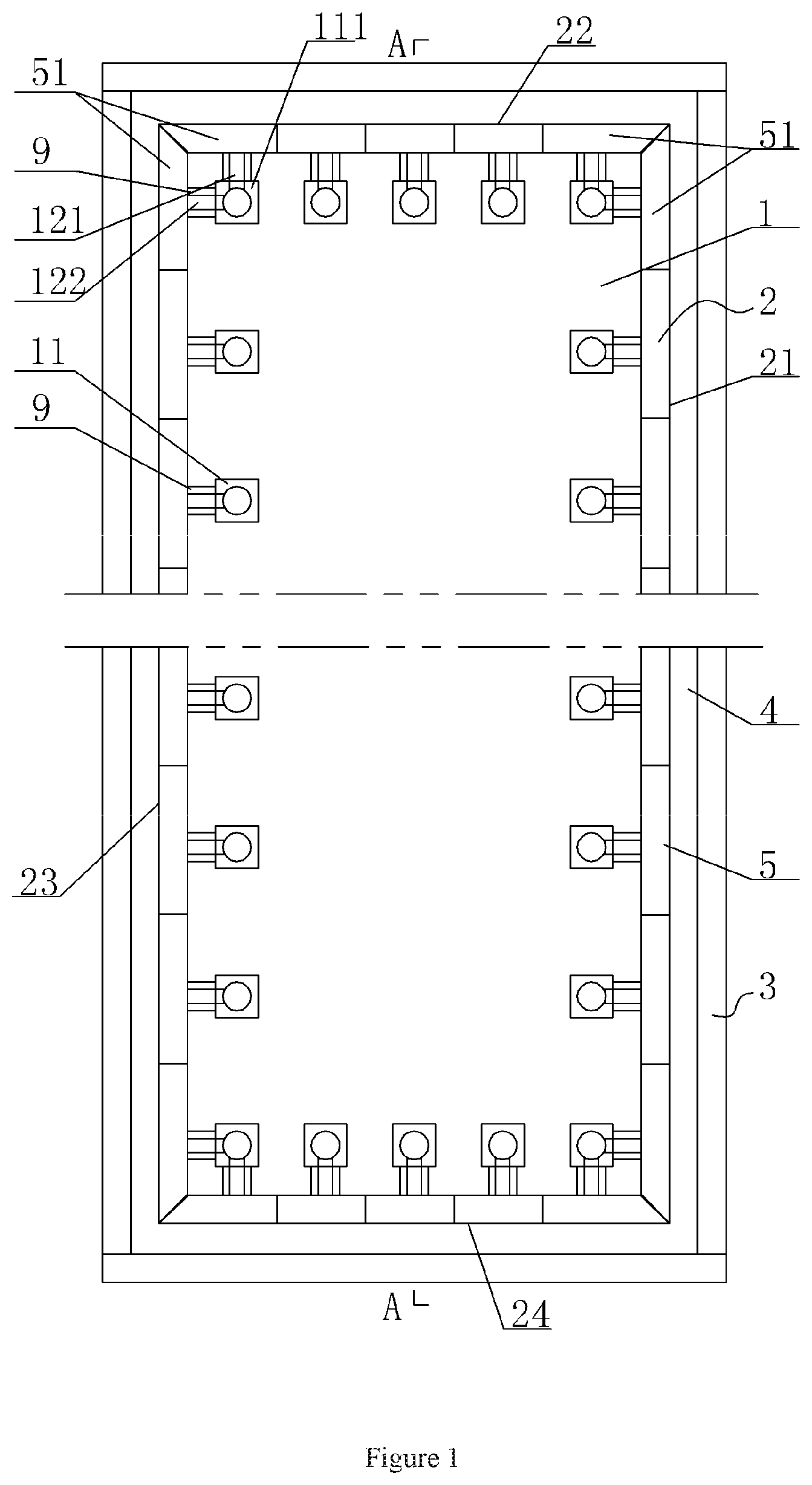
[0018] FIG. 1 is a top view of the pressing machine of the present invention;
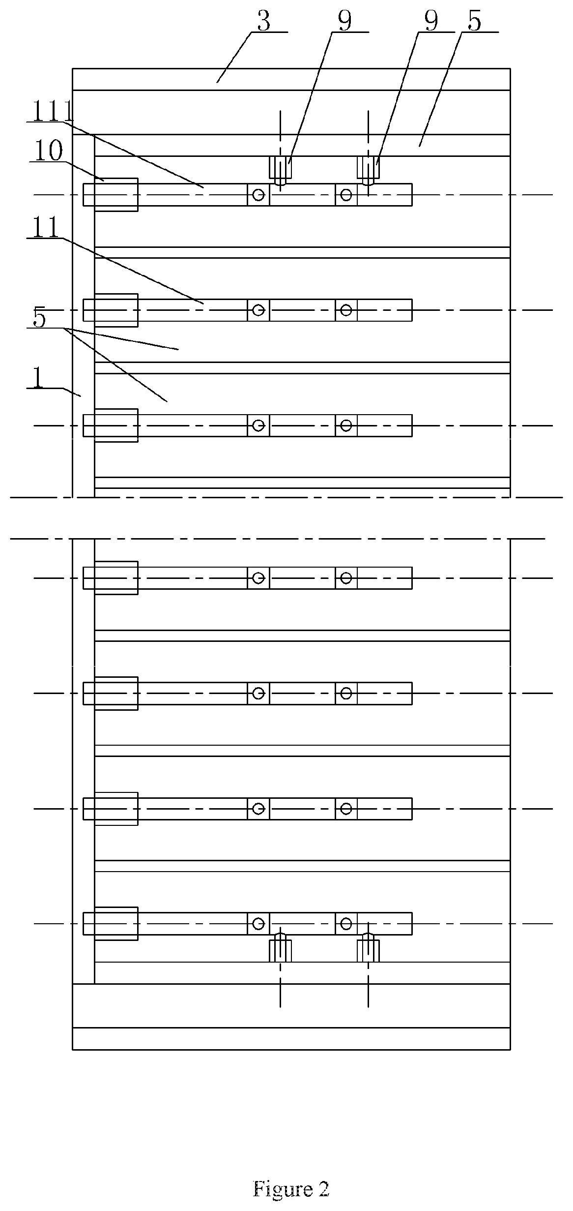
[0019] FIG. 2 is a sectional view along line A-A in FIG. 1;
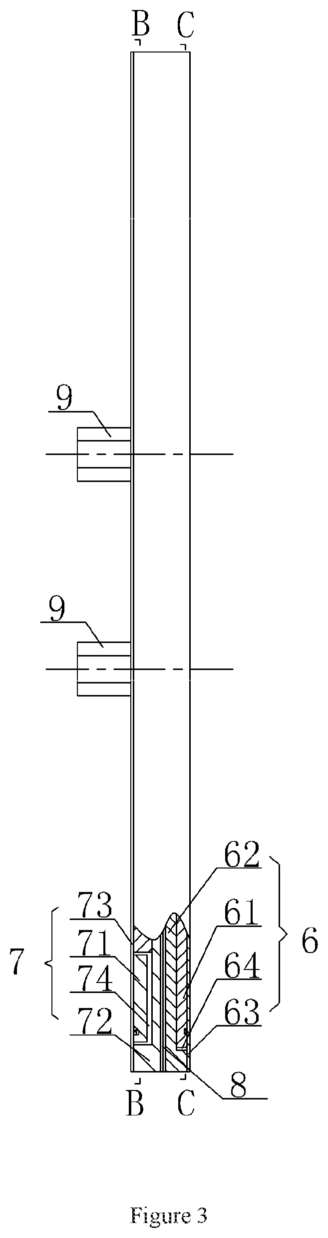
[0020] FIG. 3 is a front view of the side plate unit structure of the present invention;
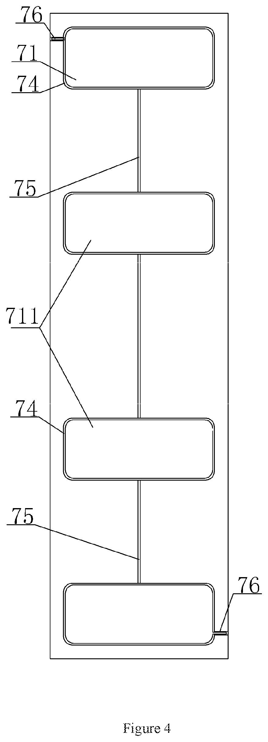
[0021] FIG. 4 is a side view of FIG. 3;
[0022] FIG. 5 is sectional view along line B-B in FIG. 3; and
[0023] FIG. 6 is a sectional view along line C-C in FIG. 3.
MARKING INSTRUCTIONS OF THE DRAWINGS
[0024] Base 1, The First Inner Edge Plate 2, The First Side Plate Assembly 21, The Second Side Plate Assembly 22, The Third Side Plate Assembly 23, The Fourth Side Plate Assembly 24, The Second Outer Edge Side Plate 3, Clamping Chamber 4, Side Plate Unit 5, Corner Side Plate unit 51, Heating Module 6, Heating Coil 61, Heating Coil Slotted Plate 62, Heating Layer Cover 63, Heating Coil Slot 64, Heating Coil End Outward-extending Slot 65, Electromagnetic Module 7, Electromagnetic Coil 71, Middle Electromagnetic Coil 711, Electromagnetic Coil Slotted Plate 72, Electromagnetic Layer Cover 73, Electromagnetic Coil Slot 74, Electromagnetic Coil Inward-extending Slot 75, Electromagnetic Coil Outward-extending Slot 76, Insulating Isolation Module 8, Inner Spigot 81, Outer Spigot 82, Positioning Threaded Structure 9, Positioning Threaded Column 10, Square Column 11, Connecting Square Column 111, Bolt 12, The First Bolt 121, The Second Bolt 122
DETAILED DESCRIPTION OF THE INVENTION
[0025] Drawings and detailed embodiments are combined hereinafter to elaborate the technical principles of the present invention.
[0026] As shown in FIGS. 1-6, a pressing machine comprises a base 1, wherein a first inner edge side plate 2 and a second outer edge side plate 3 are arranged on the base 1. A clamping chamber 4 with sealed inner and outer end surfaces is reserved between the outer wall of the first inner edge side plate 2 and the inner wall of the of the second outer edge side plate 3. The interior of the clamping chamber 4 is used for preparing sandwich panels. The first inner edge side plate 2 comprises a first side plate assembly 21, a second side plate assembly 22, a third side plate assembly 23 and a fourth side plate assembly 24, wherein the four groups of the side plate assemblies are arranged in parallel in pairs. Each side plate assembly is formed by assembling a plurality of side plate units 5 along the length direction of the corresponding side plate assembly. Each side plate unit 5 comprises a heating module 6, an electromagnetic module 7 and an insulating isolation module 8, wherein the insulating isolation module 8 is located between the heating module 6 and the electromagnetic module 7. The heating modules 6 that are located between the adjacent side plate units 5 are connected with each other, and the electromagnetic modules 7 that are located between the adjacent side plate units 5 are connected with each other.
[0027] A positioning threaded structure 9 that protrudes inwards is arranged on the inner wall of the side plate unit 5, and a positioning threaded column 10 is arranged on the base 1 and corresponds to the positioning threaded structure 9. The bottom of a square column 11 is in threaded connection with the positioning threaded column 10, and a threaded through-hole is formed in the positioning threaded column 10 that corresponds to the square column 11. A bolt 12 is in threaded connection with the corresponding threaded through-hole and the positioning threaded column 10. Therefore, the adjacent side plate units 5 are fixed to the base 1, and are in tight and seamless connection.
[0028] In this embodiment, two positioning threaded columns 10 that protrude inwards are arranged up and down on the inner wall of each side plate unit 5, thereby enabling the side plate units 5 to be stably positioned.
[0029] The two ends of each side plate assembly are respectively provided with a corner side plate unit 51, and the outer end of each corner side plate unit 51 is cut off by 45 degrees. The adjacent side plate assemblies are connected through assembling corresponding corner side plate units 51.
[0030] A connecting square column 111 that is fixed on the base 1 and corresponds to the corner side plate unit 51 is provided with two vertical-direction threaded through-holes. A first bolt 121 and a second bolt 122 are respectively in threaded connection with the corresponding threaded through-holes and the positioning threaded structures that correspond to the corner side plate unit 51.
[0031] As shown in FIGS. 3-6, the side plate unit 5 comprises a heating module 6, an electromagnetic module 7 and an insulating isolation module 8, wherein the insulating isolation module 8 is located between the heating module 6 and the electromagnetic module 7. Specifically, the heating module 6 comprises a heating coil 61, a heating coil slotted plate 62 and a heating layer cover 63. A heating coil slot 64 is formed in the heating coil slotted plate 62, and the heating coil 61 is arranged in the heating coil slot 64. The heating layer cover 63 covers the outer end surface of the heating coil slotted plate 62. Specifically, the insulating isolation module 8 is an electromagnetic isolation plate. The electromagnetic module 7 comprises electromagnetic coils 71, an electromagnetic coil slotted plate 72 and an electromagnetic layer cover 73. A plurality of electromagnetic coil slots 74 is formed in the electromagnetic coil slotted plate 72, and the electromagnetic coils 71 are embedded in the corresponding electromagnetic coil slots 74. The adjacent electromagnetic coils 71 are connected in series, and the electromagnetic layer cover 73 covers the outer end surface of the electromagnetic coil slotted plate 72. The two end surfaces of the electromagnetic isolation plate are respectively bonded with the inner end surface of the heating coil slotted plate 62 and the inner end surface of the electromagnetic coil slotted plate 72.
[0032] The heating coil 61, the heating coil slotted plate 62 and the heating layer cover 63 are tightly bonded through a strong bonding agent. Thus, the disengagement can be avoided during the pressing process, and a tight structure of the heating module 6 can be achieved.
[0033] The electromagnetic coils 71, the electromagnetic coil slotted plate 72 and the electromagnetic layer cover 73 are tightly bonded (same as the heating module) through a strong bonding agent. Therefore, the disengagement can be prevented from occurring during the pressing process, achieving a tight structure of the electromagnetic module 6.
[0034] Furthermore, heating coil outward-extending slots 65 that respectively face the adjacent side plate units 5 are formed in the heating coil slotted plate 62. The match line of the heating coil 61 is connected with the heating coil 61 of the adjacent side plate unit 5 through the corresponding heating coil outward-extending slot 65.
[0035] The heating coil 61 is mounted and fixed in the heating coil slotted plate 62 according to the size and the matching relation, enabling the outward-extending ends of the heating coil to be correctly placed in the outward-extending slots. Thus, the heating coil of one side plate unit 5 can be connected with that of the other side plate unit 5. The heating coil is mixed with the filling compound to form an integral structure so that the heating coil cannot be scattered. The heating coil is mainly made of resistance wire, and is capable of generating heat after being electrified. The heat is displayed in the form of temperature, which can be increased along the increase of the current. Namely, the temperature can be controlled through adjusting the current. In this way, the heating temperature required by the pressing process can be guaranteed, and a continuous heat preservation effect can be achieved.
[0036] In principle, as the heating coil is made of resistance wire, the electromagnetic effect cannot be produced after the heating coil is electrified. Practically, a weak magnetic effect can also be produced so that the electromagnetic effect of the electromagnetic module can be enhanced.
[0037] The heating layer cover 63 is mainly used to cover the heating coil 61 in the heating coil slotted plate 62. Thus, the heating coil 61 can be prevented from falling off.
[0038] An electromagnetic coil inward-extending slot 75 that is located between the adjacent electromagnetic coils 71 of the same side plate unit 5 is formed in the electromagnetic coil slotted plate 72. The adjacent electromagnetic coils 71 in the same side plate unit 5 are connected in series through the conductors located between the corresponding electromagnetic coil inward-extending slots 75. The electromagnetic coil slot 74 formed in one end of the electromagnetic coil slotted plate 72 is provided with an electromagnetic coil outward-extending slot 76 that faces the adjacent side plate unit 5 on one side. The electromagnetic coil slot 74 formed in the other end of the electromagnetic coil slotted plate 72 is provided with an electromagnetic coil outward-extending slot 76 that faces the adjacent side plate unit 5 on the other side. The electromagnetic coils 71 that are connected in series with the adjacent side plate units 5 through the conductors are placed into the two electromagnetic coil outward-extending slots 76.
[0039] All parts of the electromagnetic module 7 are assembled in sequence according to the size and the matching relation. The electromagnetic coils 71 are fixed in the electromagnetic coil slotted plate 72. As the electromagnetic module of the side plate unit comprises at least three coil layers, the outward-extending ends of the electromagnetic coils 72 located at the two ends of the electromagnetic coil slotted plate 72 must be correctly placed in the electromagnetic coil outward-extending slots 76, thereby ensuring that the electromagnetic coils of adjacent side plate units 5 can be correctly connected.
[0040] After the middle electromagnetic coils 711 are placed, the inward-extending ends of the middle electromagnetic coils 71 must be correctly placed in the electromagnetic coil inward-extending slots 75, thereby ensuring that the middle electromagnetic coils can be correctly connected with the electromagnetic coils at the two ends.
[0041] Similar to the heating coil, the electromagnetic coils are mixed with the filling compound to form an integral structure, thereby preventing the electromagnetic coils from being scattered. Thus, a high stability of the electromagnetic module can be achieved.
[0042] The iron core of the electromagnetic coil is made of soft iron, which cannot be made of steel. That's because steel remains a magnetic property for a long time after being magnetized and cannot be demagnetized. As a result, the magnetism of the electromagnet cannot be controlled through regulating the current so that the advantages of the electromagnet can be lost. The iron core is generally made of not pure iron but ferroferric oxide. The iron core in the electromagnet is used for increasing the magnetism of the magnet, which can also be made of other metal oxides such as manganese and cobalt. The greater the magnetic conductivity is, the larger the magnetic field is. As the magnetic conductivity of other metals is lower than that of iron, other metals are usually not adopted as the core material. The most frequently used materials are iron alloys, such as novel manganese zinc ferrite materials. Their magnetic conductivity is about 18000.
[0043] The electromagnetic coil 71 is mainly made of copper wire with moderate thickness. The magnetic field can be generated after the copper wire is electrified. The intensity of the magnetic field can be greatly enhanced under the action of the iron core. The intensity of the magnetic field is mainly displayed in the form of magnetic adsorption capacity, which can be increased along the increase of the current. Namely, the magnetic adsorption capacity can be controlled through regulating the current. Therefore, during the pressing process of sandwich panels, a necessary pressing force can be ensured, and a continuous pressing effect can be achieved.
[0044] After being electrified, the electromagnetic coil 71 generates a magnetic field. The intensity of the magnetic field is directly restricted by the number of the coil turns. Theoretically, the number of the coil turns is about 300-500.
[0045] The electromagnetic layer cover 73 is mainly used to cover the electromagnetic coils 71 in the electromagnetic coil slotted plate 72. Thus, the electromagnetic coils 71 can be prevented from falling off during operation.
[0046] In this embodiment, the electromagnetic module 7 is located on the inner wall of the electromagnetic isolation plate, and the heating module 6 is located on the outer wall of the electromagnetic isolation plate. The positioning threaded structure 9 that protrudes inwards is arranged on the inner wall of the electromagnetic layer cover 73. The electromagnetic isolation plate does not affect the electromagnetic absorption force generated by the electromagnetic module 7 between the inner sheet and the outer sheet of sandwich panels.
[0047] One side of the inner wall of the electromagnetic isolation plate is provided with an inner spigot 81, and the other side of the outer wall of the electromagnetic isolation plate is provided with an outer spigot 82. The electromagnetic module 7 is tightly attached to the end surface of the inner wall of the electromagnetic isolation plate, and the heating module 6 is tightly attached to the end surface of the outer wall of the electromagnetic isolation plate. Thus, the adjacent side plate units 5 can be quickly aligned and assembled, achieving a fast and convenient assembly process.
[0048] The description of above embodiments allows those skilled in the art to realize or use the present invention. Without departing from the spirit and essence of the present invention, those skilled in the art can combine, change or modify correspondingly according to the present invention. Therefore, the protective range of the present invention should not be limited to the embodiments above but conform to the widest protective range which is consistent with the principles and innovative characteristics of the present invention. Although some special terms are used in the description of the present invention, the scope of the invention should not necessarily be limited by this description. The scope of the present invention is defined by the claims.
* * * * *
D00000
D00001
D00002
D00003
D00004
D00005
D00006
XML
uspto.report is an independent third-party trademark research tool that is not affiliated, endorsed, or sponsored by the United States Patent and Trademark Office (USPTO) or any other governmental organization. The information provided by uspto.report is based on publicly available data at the time of writing and is intended for informational purposes only.
While we strive to provide accurate and up-to-date information, we do not guarantee the accuracy, completeness, reliability, or suitability of the information displayed on this site. The use of this site is at your own risk. Any reliance you place on such information is therefore strictly at your own risk.
All official trademark data, including owner information, should be verified by visiting the official USPTO website at www.uspto.gov. This site is not intended to replace professional legal advice and should not be used as a substitute for consulting with a legal professional who is knowledgeable about trademark law.