Loading Unit And Adapter With Modified Coupling Assembly
Beardsley; John W.
U.S. patent application number 16/800100 was filed with the patent office on 2020-10-08 for loading unit and adapter with modified coupling assembly. The applicant listed for this patent is Covidien LP. Invention is credited to John W. Beardsley.
| Application Number | 20200315621 16/800100 |
| Document ID | / |
| Family ID | 1000004720660 |
| Filed Date | 2020-10-08 |


View All Diagrams
| United States Patent Application | 20200315621 |
| Kind Code | A1 |
| Beardsley; John W. | October 8, 2020 |
LOADING UNIT AND ADAPTER WITH MODIFIED COUPLING ASSEMBLY
Abstract
A surgical stapling device includes a body portion and a tool assembly. The body portion includes a base member that defines a longitudinal slot and spaced keyways. The tool assembly includes a mounting member that defines a channel having an open end that is dimensioned to receive the base member of the body portion. The mounting member includes locking tabs that are positioned within the channel. Each of the locking tabs is configured to be received within one of the spaced keyways of the base member to releasably secure the tool assembly to the body portion.
| Inventors: | Beardsley; John W.; (Wallingford, CT) | ||||||||||
| Applicant: |
|
||||||||||
|---|---|---|---|---|---|---|---|---|---|---|---|
| Family ID: | 1000004720660 | ||||||||||
| Appl. No.: | 16/800100 | ||||||||||
| Filed: | February 25, 2020 |
Related U.S. Patent Documents
| Application Number | Filing Date | Patent Number | ||
|---|---|---|---|---|
| 62828204 | Apr 2, 2019 | |||
| Current U.S. Class: | 1/1 |
| Current CPC Class: | A61B 2017/07271 20130101; A61B 2017/07285 20130101; A61B 17/072 20130101; A61B 2017/07257 20130101; A61B 2017/00477 20130101; A61B 2017/0053 20130101 |
| International Class: | A61B 17/072 20060101 A61B017/072 |
Claims
1. A surgical stapling device comprising: a body portion including a housing, a base member supported by the housing, and a drive assembly supported within the housing, the base member defining a longitudinal slot and spaced keyways, the drive assembly including a proximal portion having a connector and a distal portion including a working end, the drive assembly being movable within the housing between a retracted position in which the working end of the drive assembly is positioned within the longitudinal slot of the base member and an advanced position; and a tool assembly including a first jaw, a second jaw, and a mounting member, the first jaw and the second jaw being secured to the mounting member such that the first jaw is movable in relation to the second jaw between an open position and an unclamped position, the mounting member defining a channel having an open end that is dimensioned to receive the base member of the body portion, the mounting member including locking tabs, each of the locking tabs being configured to be received within one of the spaced keyways of the base member to releasably secure the tool assembly to the body portion.
2. The surgical stapling device of claim 1, wherein each of the spaced keyways includes an axial portion and a radial portion and axial movement of the tool assembly in relation to the body portion moves the locking tabs through the axial portions of the keyways and rotatable movement of the tool assembly in relation to the body portion moves the locking tabs through the radial portions of the spaced keyways to secure the tool assembly to the body portion.
3. The surgical stapling device of claim 2, wherein the working end of the drive assembly is configured to be movable through the tool assembly when the drive assembly is moved from the retracted position to the advanced position to move the tool assembly from the open position to the clamped position and to fire the tool assembly.
4. The surgical stapling device of claim 3, wherein the body portion includes a lead screw and an inner tube, the lead screw being rotatable to axially advance the inner tube within the housing, the inner tube engaging the connector of the drive assembly to axially advance the drive member within the housing from the retracted position to the advanced position.
5. The surgical stapling device of claim 4, wherein the body portion includes a biasing member positioned between a distal portion of the inner tube and the connector, the biasing member being positioned to urge the drive assembly distally within the housing in relation to the inner shaft.
6. The surgical stapling device of claim 5, wherein the first jaw includes an anvil and the second jaw includes a channel member that supports a staple cartridge.
7. The surgical stapling device of claim 6, wherein the working end of the drive member includes a vertical strut having a knife edge and the channel member and staple cartridge define longitudinal slots that receive the vertical strut when the tool assembly is secured to the body portion.
8. The surgical stapling device of claim 7, wherein when the locking tabs are in the axial portions of the spaced keyways, the vertical strut of the working end of the drive assembly is misaligned with the longitudinal slot in the channel member such that when the tool assembly is moved towards the base member to move the locking tabs through the axial portions of the spaced keyways, the working end of the drive assembly abuts the channel member to prevent axial movement of the drive assembly in relation to the tool assembly.
9. The surgical stapling device of claim 8, wherein axial advancement of the base member within the channel of the mounting member when the working end of the drive assembly is in abutment with the channel member causes the drive assembly to move axially in relation to the inner tube to compress the biasing member.
10. The surgical stapling device of claim 9, wherein when the tool assembly is rotated in relation to body portion to move the locking tabs through the radial portions of the spaced keyways, the vertical strut of the drive assembly is moved into alignment with the longitudinal slots of the channel member and the staple cartridge.
11. The surgical stapling device of claim 10, wherein when the vertical strut is rotated into alignment with the longitudinal slots of the channel member and the staple cartridge, the biasing member urges the working end of the drive assembly into a proximal portion of the tool assembly.
12. The surgical stapling device of claim 1, wherein the housing includes a distal portion, the base member being pivotally supported on the distal portion of the housing.
13. The surgical stapling device of claim 12, wherein the body portion includes a platform that is supported on the distal portion of the housing.
14. The surgical stapling device of claim 13, wherein the base member defines a transverse slot and the platform includes a flange that is pivotably received within the transverse slot of the base member.
15. The surgical stapling device of claim 14, wherein the platform defines upper and lower recesses that diverge outwardly in a distal direction.
16. The surgical stapling device of claim 15, wherein the drive assembly includes an elongate flexible body having an upper body portion and a lower body portion, the platform is positioned between the upper and lower body portions.
17. The surgical stapling device of claim 16, further including upper and lower U-shaped guides, the upper guide being positioned in the upper recess of the platform and receiving the upper body portion of the flexible body of the drive assembly, and the lower guide being positioned in the lower recess of the platform and receiving the lower body portion of the flexible body of the drive assembly.
18. The surgical stapling device of claim 17, wherein each of the upper and lower U-shaped guides have a proximal portion including a pivot member, the pivot members pivotably supporting the upper and lower U-shaped guides within the upper and lower recesses.
19. The surgical stapling device of claim 18, further including an upper blowout plate assembly positioned within the upper guide on opposite sides of the upper body portion of the flexible body and a lower blowout plate assembly positioned within the lower guide on opposite sides of the lower body portion of the flexible body.
20. The surgical stapling device of claim 12, further including an articulation assembly having an articulation drive member, a first articulation link secured to the articulation drive member, a second articulation link pivotably coupled to the first articulation link and to the base member.
Description
BACKGROUND
1. Technical Description
[0001] The present disclosure is directed to a loading unit and adapter assembly for a surgical stapling device and, more particularly, to a loading unit and adapter assembly for a surgical stapling device including a modified coupling assembly for connecting the loading unit to the adapter assembly.
2. Background of Related Art
[0002] Stapling devices for suturing body tissue during surgical procedures are well known. The stapling devices include a tool assembly having an anvil and a staple cartridge that supports a plurality of surgical staples. The staples can be driven from the staple cartridge into the anvil to staple tissue clamped between the staple cartridge and the anvil. Some stapling devices include a knife member that is adapted to cut body the tissue clamped between the anvil and the staple cartridge as the tissue is being stapled. These stapling devices have reduced the amount of time required to perform surgical procedures by reducing the time required to join tissue segments during the surgical procedure.
[0003] In order to minimize costs associated with performing surgical procedures, known stapling devices include a loading unit or reload that is removably attached to an adapter assembly of the stapling device. After the staples are fired from the staple cartridge into the anvil through the tissue, the loading unit can be replaced to facilitate reuse of the stapling device.
[0004] Generally, a loading unit includes a proximal body portion and a tool assembly pivotally supported on a distal end of the proximal body portion. The proximal body portion of the loading unit supports a drive assembly and an articulation link and includes a proximal end that is adapted to engage an adapter or body of a stapling device such that the drive assembly of the loading unit is coupled with a drive member of the stapling device and the articulation link of the loading unit is coupled to an articulation mechanism of the stapling device.
[0005] In some instances, if the drive assembly of the loading unit is not properly coupled to the drive member of the surgical stapling device, the tool assembly can be locked in a clamped position after the stapling device is fired. In addition, coupling of the articulation link of the loading unit to the articulation mechanism of the stapling device generally requires multiple components with clearances that cause the tool assembly to wobble during firing and retraction of the drive assembly.
[0006] A continuing need exists in the stapling arts for a stapling device including a loading unit that can be selectively coupled to a body of the stapling device in a manner to ensure proper engagement of the components of the reload with the components of the stapling device to provide a reliable and stable device.
SUMMARY
[0007] One aspect of the disclosure is directed to a surgical stapling device including a body portion and a tool assembly. The body portion includes a housing, a base member positioned on the housing, and a drive assembly supported within the housing. The base member defines a longitudinal slot and spaced keyways. The drive assembly includes a proximal portion having a connector and a distal portion including a working end. The drive assembly is movable within the housing between a retracted position in which the working end of the drive assembly is positioned within the longitudinal slot of the base member and an advanced position. The tool assembly includes a first jaw, a second jaw, and a mounting member. The first jaw and the second jaw are secured to the mounting member such that the first jaw is movable in relation to the second jaw between an open position and an unclamped position. The mounting member defines a channel having an open end that is dimensioned to receive the base member of the body portion. The mounting member includes locking tabs positioned within the channel. Each of the locking tabs is configured to be received within one of the spaced keyways of the base member to releasably secure the tool assembly to the body portion.
[0008] In some embodiments, each of the spaced keyways includes an axial portion and a radial portion, wherein axial movement of the tool assembly in relation to the body portion moves the locking tabs through the axial portions of the keyways and rotatable movement of the tool assembly in relation to the body portion moves the locking tabs through the radial portions of the spaced keyways to secure the tool assembly to the body portion.
[0009] In certain embodiments, the working end of the drive assembly is configured to be movable through the tool assembly when the drive assembly is moved from the retracted position to the advanced position to move the tool assembly from the open position to the clamped position and to fire the tool assembly.
[0010] In embodiments, the body portion includes a lead screw and an inner tube, and the lead screw is rotatable to axially advance the inner tube within the housing, wherein the inner tube engages the connector of the drive assembly to axially advance the drive member within the housing from the retracted position to the advanced position.
[0011] In some embodiments, the body portion includes a biasing member that is positioned between a distal portion of the inner tube and the connector to urge the drive assembly distally within the housing in relation to the inner shaft.
[0012] In certain embodiments, the first jaw includes an anvil and the second jaw includes a channel member that supports a staple cartridge.
[0013] In embodiments, the working end of the drive member includes a vertical strut having a knife edge and the channel member and staple cartridge define longitudinal slots that receive the vertical strut when the tool assembly is secured to the body portion.
[0014] In some embodiments, when the locking tabs are in the axial portions of the spaced keyways, the vertical strut of the working end of the drive assembly is misaligned with the longitudinal slot in the channel member such that when the tool assembly is moved towards the base member to move the locking tabs through the axial portions of the spaced keyways, the working end of the drive assembly abuts the channel member to prevent axial movement of the drive assembly in relation to the tool assembly.
[0015] In certain embodiments, axial advancement of the base member within the channel of the mounting member when the working end of the drive assembly is in abutment with the channel member causes the drive assembly to move axially in relation to the inner tube to compress the biasing member.
[0016] In embodiments, when the tool assembly is rotated in relation to body portion to move the locking tabs through the radial portions of the spaced keyways, the vertical strut of the drive assembly is moved into alignment with the longitudinal slots of the channel member and the staple cartridge.
[0017] In some embodiments, when the vertical strut is rotated into alignment with the longitudinal slots of the channel member and the staple cartridge, the biasing member urges the working end of the drive assembly into a proximal portion of the tool assembly.
[0018] In certain embodiments the housing includes a distal portion, and the base member is pivotally supported on the distal portion of the housing.
[0019] In embodiments, the body portion includes a platform that is supported on the distal portion of the housing.
[0020] In some embodiments, the base member defines a transverse slot and the platform includes a flange that is pivotably received within the transverse slot of the base member.
[0021] In certain embodiments, the platform defines upper and lower recesses that diverge outwardly in a distal direction.
[0022] In embodiments, the drive assembly includes an elongate flexible body having an upper body portion and a lower body portion, and the platform is positioned between the upper and lower body portions.
[0023] In some embodiments, the stapling device includes upper and lower U-shaped guides, wherein the upper guide is positioned in the upper recess of the platform and receives the upper body portion of the flexible body of the drive assembly and the lower guide is positioned in the lower recess of the platform and receives the lower body portion of the flexible body of the drive assembly.
[0024] In certain embodiments, each of the upper and lower U-shaped guides has a proximal portion including a pivot member, wherein the pivot members pivotably support the upper and lower U-shaped guides within the upper and lower recesses.
[0025] In embodiments, the stapling device includes an upper blowout plate assembly positioned within the upper guide on opposite sides of the upper body portion of the flexible body and a lower blowout plate assembly positioned within the lower guide on opposite sides of the lower body portion of the flexible body.
[0026] In some embodiments, the stapling device includes an articulation assembly having an articulation drive member, a first articulation link secured to the articulation drive member, a second articulation link pivotably coupled to the first articulation link and to the base member.
BRIEF DESCRIPTION OF THE DRAWINGS
[0027] Various embodiments of the presently disclosed loading unit and adapter assembly are described herein below with reference to the drawings, wherein:
[0028] FIG. 1 is a side perspective view of a surgical stapling device including an exemplary embodiment of the presently disclosed loading unit and adapter assembly;
[0029] FIG. 2 is an exploded perspective view of the loading unit of the surgical stapling device shown in FIG. 1;
[0030] FIG. 2A is a perspective view from the distal end of an end cap of the loading unit of the surgical stapling device shown in FIG. 2;
[0031] FIG. 3 is a side perspective view of the loading unit and adapter assembly shown in FIG. 1 with the loading unit separated from the adapter assembly;
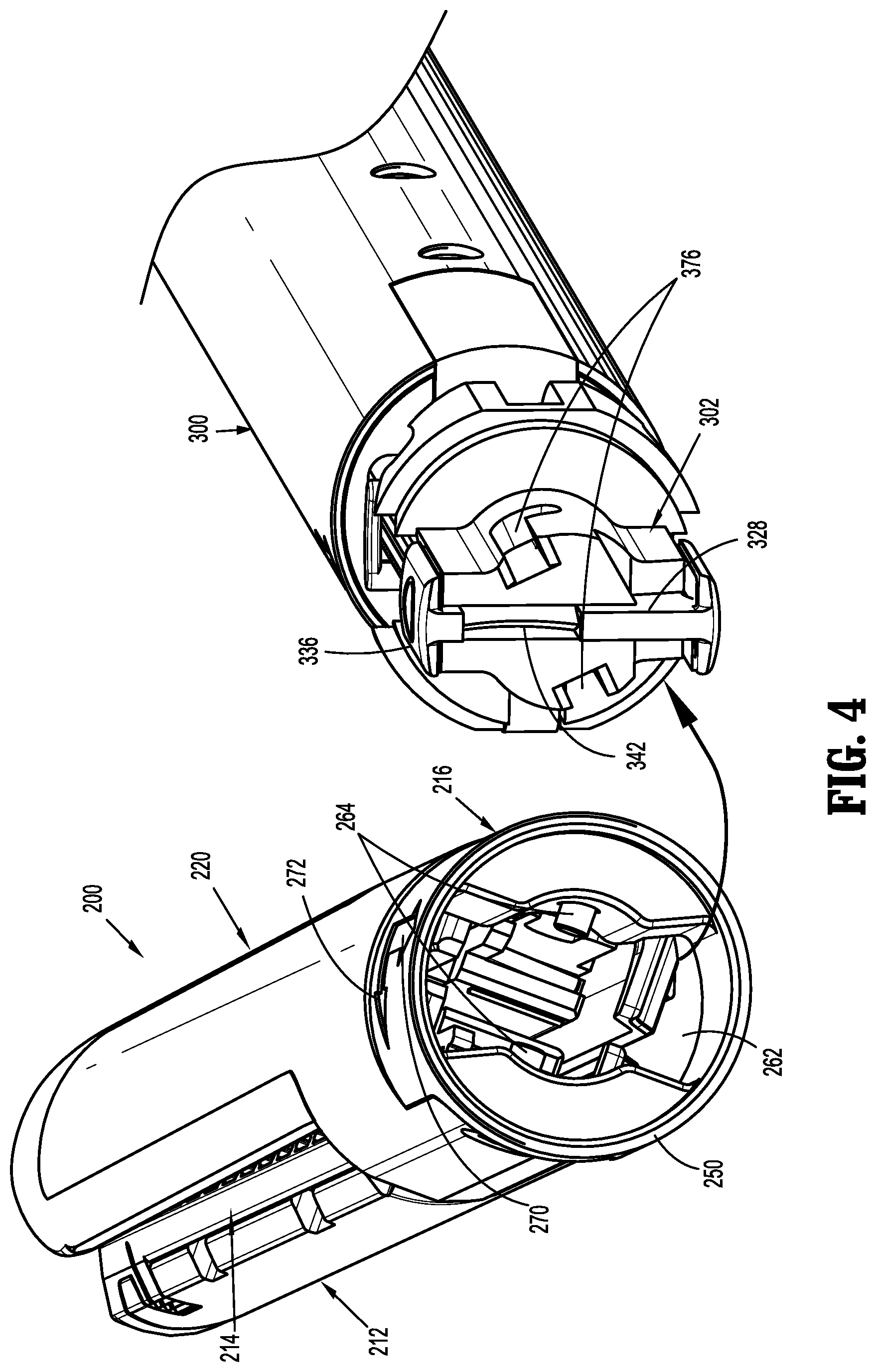
[0032] FIG. 4 is a perspective view of the proximal end of the loading unit and the distal end of the adapter assembly with the loading unit separated from the adapter assembly;
[0033] FIG. 5 is an exploded perspective view of the adapter assembly of the surgical stapling device shown in FIG. 1;
[0034] FIG. 6 is an enlarged view of the indicated area of detail shown in FIG. 3;
[0035] FIG. 6A is a side perspective view of the pivot base of the adapter assembly shown in FIG. 5;
[0036] FIG. 6b is a top perspective view of the pivot base of the adapter assembly shown in FIG. 6A;
[0037] FIG. 7 is a side perspective view of a distal end of the adapter assembly shown in FIG. 3 with an outer tube and a housing half-section removed;
[0038] FIG. 7A is a side perspective view of a drive assembly guide of the adapter assembly shown in FIG. 5;
[0039] FIG. 8 is a side perspective view of the distal end of the adapter assembly shown in FIG. 7 with the outer tube, the housing half-section, and the drive member removed;
[0040] FIG. 9 is a cross-sectional view taken along section line 9-9 of FIG. 3;
[0041] FIG. 10 is an enlarged view of the indicated area of detail shown in FIG. 9;
[0042] FIG. 11 is a cross-sectional view of the loading unit and the distal end of the adapter assembly of the surgical stapling device shown in FIG. 1 with the loading unit separated from the adapter assembly;
[0043] FIG. 12 is an enlarged view of the indicated area of detail shown in FIG. 9;
[0044] FIG. 13 is a cross-sectional view of the loading unit and the distal end of the adapter assembly of the surgical stapling device shown in FIG. 11 as the loading unit is moved axially towards the adapter assembly to initiate coupling of the loading unit with the adapter assembly;
[0045] FIG. 14 is a cross-sectional view of the loading unit and the distal end of the adapter assembly of the surgical stapling device shown in FIG. 13 as the loading unit continues to be axially advanced and coupled to the adapter assembly;
[0046] FIG. 15 is an enlarged view of the indicated area of detail shown in FIG. 5;
[0047] FIG. 16 is a cross-sectional view of a proximal portion of the adapter assembly shown in FIG. 14 with a drive member biasing member of the adapter assembly fully compressed;
[0048] FIG. 17 is a cross-sectional view taken along section line 17-17 of FIG. 14;
[0049] FIG. 18 is a cross-sectional view taken along section line 18-18 of FIG. 14;
[0050] FIG. 19 is a side cross-sectional view of the loading unit and the distal end of the adapter assembly of the surgical stapling device shown in FIG. 14 as the loading unit is rotated in relation to the adapter assembly to fully couple to loading unit to the adapter assembly;
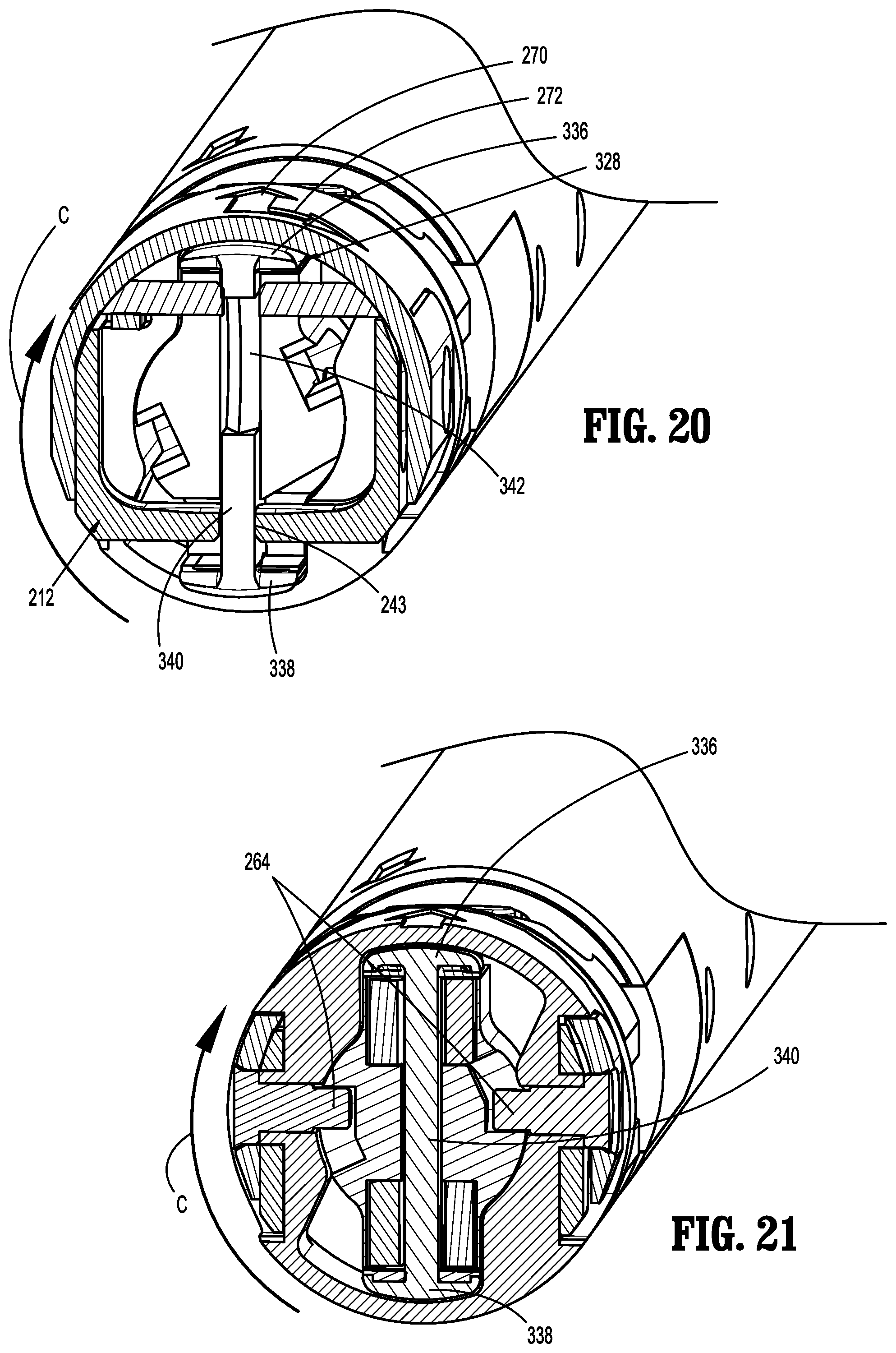
[0051] FIG. 20 is a cross-sectional view taken along section line 20-20 of FIG. 19; and
[0052] FIG. 21 is a cross-sectional view taken along section line 21-21 of FIG. 19.
DETAILED DESCRIPTION OF EMBODIMENTS
[0053] The presently disclosed stapling device including a loading unit and an adapter assembly will now be described in detail with reference to the drawings in which like reference numerals designate identical or corresponding elements in each of the several views. However, it is to be understood that the disclosed embodiments are merely exemplary of the disclosure and may be embodied in various forms. Well-known functions or constructions are not described in detail to avoid obscuring the present disclosure in unnecessary detail. Therefore, specific structural and functional details disclosed herein are not to be interpreted as limiting, but merely as a basis for the claims and as a representative basis for teaching one skilled in the art to variously employ the present disclosure in virtually any appropriately detailed structure.
[0054] In this description, the term "proximal" is used generally to refer to that portion of the device that is closer to a clinician, while the term "distal" is used generally to refer to that portion of the device that is farther from the clinician. In addition, the term "endoscopic" is used generally used to refer to endoscopic, laparoscopic, arthroscopic, and/or any other procedure conducted through a small diameter incision or cannula. Further, the term "clinician" is used generally to refer to medical personnel including doctors, nurses, and support personnel.
[0055] FIGS. 1 and 2 illustrate a surgical stapling device shown generally as stapling device 10 including a handle assembly 100, and exemplary embodiments of the presently disclosed tool assembly 200 (e.g., an end effector, multiple or single use tool assembly) and adapter assembly 300. The adapter assembly 300 includes an elongate body 308 having a distal portion that supports the tool assembly 200. The handle assembly 100 is configured for releasable connection to the adapter assembly 300, and, in turn, the adapter assembly 300 is configured for releasable connection to the tool assembly 200. Together, the handle assembly 100 and the adapter assembly 300 cooperate to actuate the tool assembly 200. The stapling device 10 may be an electromechanically powered system and the handle assembly 100 may support a power source, e.g., a battery pack. Alternatively, the stapling device 10 may be manually actuated and the adapter assembly 300 may be fixedly secured to the handle assembly 100.
[0056] In embodiments, the handle assembly 100 includes a stationary handle 102 and a plurality of actuation switches 104. The actuation switches 104 are provided to control various functions of the stapling device 10 including approximation of the tool assembly 200, and cutting, and firing of tissue.
[0057] FIG. 2 illustrates an exemplary embodiment of the presently disclosed tool assembly 200 of the stapling device 10 (FIG. 1) which includes an anvil assembly 210, and a cartridge assembly 211. The cartridge assembly 211 includes a cartridge channel member 212, and a staple cartridge 214. The anvil assembly 210 includes an anvil cover 220 and an anvil plate 222. The anvil cover 220 includes a mounting portion 224 that defines a proximal cutout 226, and a cover portion 228 that extends along the distal portion of the anvil plate 222. The mounting portion 224 includes spaced proximal extensions 224a that define the cutout 226 and bores 225. The tool assembly 200 also includes a mounting member 216 that is secured to the proximal portions of the anvil assembly 210 and the cartridge assembly 211.
[0058] The anvil plate 222 includes a tissue engaging surface 230 that is in opposed relation to the staple cartridge 214 and defines a plurality of staple deforming recesses (not shown). The anvil plate 222 has a side opposite to the tissue engaging surface 230 that defines an elongated recess 232 that is configured to receive an upper beam 336 (FIG. 4) of a drive assembly 320 (FIG. 14) of the adapter assembly 300 as described in further detail below. The anvil cover 220 is secured to the anvil plate 222, e.g., by welding or crimping, such that the cover portion 228 encloses the elongated recess 232. The anvil plate 222 also defines an elongated knife slot 236 that extends through the tissue engaging surface 230 of the anvil plate 222 into the elongated recess 232.
[0059] The cartridge channel member 212 includes a bottom wall 240 and a pair of spaced side walls 242 that define a channel 244. The channel 244 is dimensioned to receive the staple cartridge 214. The side walls 242 of the channel member 212 each include a proximal extension 246 that defines a bore 246a. The bottom wall 240 defines a longitudinal slot 243 (FIG. 17) that is open at its proximal end to receive a working end 328 (FIG. 5) of the drive assembly 320 as described in detail below. The staple cartridge 214 also defines a longitudinal slot 214a that is aligned with the longitudinal slot 243 of the channel member 212.
[0060] Referring also to FIG. 2A, the mounting member 216 includes a substantially cylindrical proximal portion 250 and a distal portion 252. The distal portion 252 of the mounting member 216 defines an I-shaped slot 255 (FIG. 2A) and includes flat outer side walls 254 that define bores 254a. The side walls 254 are received between the pair of proximal extensions 224a of the mounting portion 224 of the anvil cover 220 within the cutout 226 such that the bores 225 of the proximal extensions 224a are aligned with the bores 254a of the mounting member 216. The extensions 246 of the side walls 242 of the channel member 212 are also positioned between the flat side walls 254 of the mounting member 216 and the proximal extensions 224a of the anvil cover 220 such that the bores 246a are aligned with the bores 225 of the anvil cover and with the bores 254a of the mounting member 216.
[0061] A pivot pin 260 is positioned through each of the bores 225 of the anvil cover 220, the bores 246a of the channel member 212, and the bores 254a of the mounting member 216 on each side of the anvil assembly 210 to fixedly secure the anvil assembly 210 to the mounting member 216, and to pivotably secure the cartridge channel member 212 in relation to the mounting member 216 and the anvil assembly 210. The channel member 212 is pivotal about the pivot pins 260 from an open position (FIG. 1) to a clamped position (FIG. 3).
[0062] Referring to FIGS. 2-4, a distal portion of the adapter assembly 300 (FIG. 3) is dimensioned to be received in the proximal portion 250 (FIG. 2) of the mounting member 216 to releasably couple the tool assembly 200 to the adapter assembly 300. More specifically, the proximal portion 250 of the mounting member 216 defines a channel 262 that is configured to receive a pivot base 302 (FIG. 4) of the adapter assembly 300 which is described in further detail below. The mounting member 216 includes locking tabs 264 (FIG. 4) that project inwardly from an inner surface of the mounting member 216 into the channel 262. In embodiments, an outer surface of the mounting member 216 includes a pair of arrows 270, 272 that extend in directions perpendicular to each other. A first arrow 270 of the pair of arrows points in a direction that is parallel to a longitudinal axis "X" of the tool assembly 200 and the second arrow 272 of the pair of arrows points in a direction that is perpendicular to the longitudinal axis "X" of the tool assembly 200. The arrows 270, 272 assist a clinician with coupling the tool assembly 200 to the adapter assembly 300 as described in detail below.
[0063] Referring to FIGS. 4-10, the adapter assembly 300 includes a housing 304 (FIG. 9) that includes an upper housing portion 304a and a lower housing portion 304b. The upper and lower housing portions 304a, 304b are secured together using any of a variety of known fastening technique, e.g., welding, interlocking structure, etc., to define a cavity 306 (FIG. 9) that receives other components of the adapter assembly 300. A distal portion of each of the upper and lower housing portions 304a, 304b defines a recess 310 and a cutout 312 (FIG. 5). The recesses 310 of the upper and lower housing portions 304a, 304b diverge outwardly in the distal direction. The upper and lower housing portions 304a, 304b are supported within an outer cylindrical housing 313 to prevent separation of the upper housing portion 304a from the lower housing portion 304b.
[0064] The cutouts 312 of the upper and lower housing portions 304a, 304b define a slot in the distal end of the housing 304 that receives a platform 314 (FIG. 5) when the upper and lower housing portions 304a, and 304b are assembled. The platform 314 can be secured between the upper and lower housing portions 304a, 304b using any known fastening technique including screws, welding or the like. The platform 314 defines upper and lower recesses 316 (FIG. 5) that have shapes that correspond to the shapes of the recesses 310 in the upper and lower housing portions 304a, 304b. When the platform 314 is secured between the upper and lower housing portions 304a, 304b, the recesses 310 of the upper and lower housing portions 304a, 304b and the recesses 316 of the platform 314 define upper and lower cavities 318 (FIG. 7) at the distal portion of the housing 304 that diverge outwardly in the distal direction.
[0065] The adapter assembly 300 includes the pivot base 302, a drive assembly 320, a lead screw 322, a firing nut 324, and an inner tube 326. The pivot base 302 defines a longitudinal slot 302a and the lead screw 322 includes a threaded outer wall 322a. The drive assembly 320 is positioned within the housing 304 (FIG. 9) and includes a distal working end 328, a proximal connector 330, and an elongate flexible body 332 positioned between the working end 328 and the connector 330. The flexible body 332 includes an upper body portion 332a and a lower body portion 332b. The working end 328 includes an upper beam 336, a lower beam 338, and a vertical strut 340. The vertical strut 340 includes a knife edge 342. When the drive assembly 320 is in a retracted position, the vertical strut 340 is positioned within the longitudinal slot 302a of the pivot base 302. The upper and lower beams 336, 338 are positioned to engage the anvil assembly 210 and the cartridge channel member 212 to move the anvil assembly 210 and the cartridge channel member 212 between open and clamped positions as is known in the art. For a more detailed description of the working end 328 of the drive assembly 320, see U.S. Pat. No. 5,865,361 ("'361 patent") which is incorporated herein by reference in its entirety.
[0066] Referring briefly to FIG. 15, the connector 330 extends proximally from the flexible body 332 of the drive assembly 320 and includes a distal portion 346 and a proximal portion 348. The distal portion 346 of the connector 330 is secured to a proximal end of the flexible body 332 between the upper body portion 332a and a lower body portion 332b of the flexible body 332. The proximal portion 348 of the connector 330 includes an annular recess 350 (FIG. 10) and is configured to be received within a distal end of the firing nut 324. Pins 352 extend through a distal portion of the firing nut 324 through the annular recess 350 of the connector 330 to secure the distal portion of the firing nut 324 to the connector 330. The annular recess 350 has a length that is greater than the diameter of the pins 352 such that the connector 330 is axially movable within the firing nut 324 independently of the firing nut 324. More specifically, the connector 330 is axially movable in relation to the firing nut 324 between an advanced position (FIG. 10) in which the pins 352 engage a proximal wall 350a defining the proximal end of the annular recess 350 and a retracted position (FIG. 16) in which the pins 352 engage a distal wall 350b defining the distal end of the annular recess 350. The connector 330 translates movement of the firing nut 324 into movement of the drive assembly 320 when the pins 352 are engaged with the walls 350a and 350b defining the annular recess 350.
[0067] Referring again to FIGS. 4-10, the firing nut 324 includes an inner wall having a threaded portion 356 (FIG. 9) and an outer side wall defining a flat 358 (FIG. 5). The threaded portion 356 is positioned to engage the threaded outer wall 322a of the lead screw 322 such that rotation of the lead screw 322 within the firing nut 324 causes longitudinal movement of the firing nut 324 within the housing 304 (FIG. 9). The inner tube 326 includes an inner wall having a flat surface portion (not shown) that defines an axial bore 360 (FIG. 5). The flat surface portion of the inner wall of the inner tube 326 is positioned to engage the flat 358 (FIG. 5) on the outer side wall of the firing nut 324 to prevent rotation of the firing nut 324 within the inner tube 326 of the adapter assembly 300. The inner tube 326 also has an outer wall that defines a flat 362. The flat 362 of the inner tube 326 is positioned within the housing 304 to prevent rotation of the inner tube 326 within the housing 304.
[0068] In use, when the lead screw 322 is rotated within the firing nut 324, engagement between the threaded outer wall 322a of the lead screw 322 and the threaded portion 356 (FIG. 9) of the inner wall of the firing nut 324 causes axial movement of the firing nut 324 within the inner tube 326 of the adapter assembly 300. As discussed above, engagement between the flat 358 of the firing nut 324 and the flat surface portion (not shown) on the inner wall of the inner tube 326 prevents the firing nut 324 from rotating and, thus, limits the firing nut 324 to axial movement within the inner tube 326 of the adapter assembly 300. As the firing nut 324 is moved axially within the inner tube 326, the pins 352 are moved within the annular recess 350 of the connector 330 until the pins 352 engage one of the ends 350a, 350b of the wall defining the annular recess 350. When this occurs, axial movement of the firing nut 324 will cause axial movement of the connector 330 and corresponding axial movement of the drive assembly 320. Axial movement of the drive assembly 320 causes the working end 328 of the drive assembly 320 to move within the tool assembly 200 to actuate the tool assembly 200 as is known in the art.
[0069] As discussed above, the platform 314 (FIG. 5) is secured between a distal portion of the upper and lower housing portions 304a, 304b and defines upper and lower cavities 318 (FIG. 7) (only the upper cavity is shown). A distal end of the platform 318 includes a flange 364 (FIG. 5) that extends distally from the housing 304 of the adapter 300. The flange 364 defines a bore 366.
[0070] Referring to FIGS. 6A and 6B, the pivot base 302 includes a body 370 (FIG. 5) having a distal portion 372 that defines the longitudinal slot 302a and a proximal portion 374. The distal portion 372 of the body 370 is dimensioned to be received in the channel 262 (FIG. 4) defined in the proximal portion 250 (FIG. 2) of the mounting member 216 and defines spaced keyway slots 376. Each of the keyway slots 376 is dimensioned to receive one of the locking tabs 264 (FIG. 4) of the mounting member 216 when the tool assembly 200 is secured to the adapter assembly 300. The keyway slots 376 are substantially J-shaped and have an axial portion 378 and a transverse portion 380.
[0071] The proximal portion 374 of the body 370 of the pivot base 302 has a radiused proximal end 382 and defines a transverse through slot 384 and a vertical opening 386 (FIG. 6B). The slot 384 receives the flange 364 (FIG. 5) of the platform 314. A pivot member 388 is received through the opening 386 in the proximal portion 374 of the pivot base 302 and the vertical bore 366 in the flange 364 of the platform 314 to pivotably secure the pivot base 302 to the platform 314. In embodiments, top and bottom surfaces of the proximal portion 374 of the body 370 of the pivot base 302 define annular guide channels 390 (FIG. 6B).
[0072] Referring to FIGS. 5 and 7-8, the adapter 300 (FIG. 1) includes upper and lower drive assembly guides 392. Each of the guides 392 (FIG. 7A) is substantially U-shaped and includes side walls 394, a base wall 396, and an open end 398 opposite to the base wall 396 that define a channel 392a that has a divergent distal portion 393. The open end 398 of the guides 392 is dimensioned to receive one of the upper and lower body portions 332a, 332b of the flexible body 332 of the drive assembly 320. The base wall 396 defines spaced elongated slots 400 (FIG. 5) and includes a proximal circular pivot member 402. The pivot member 402 is received within an opening 404 (FIG. 5) that is formed in a proximal end of the platform 314 to pivotably secure each of the drive assembly guides 392 within one of the cavities 318 of the platform 314 (FIG. 6) in the distal end of the housing 304.
[0073] The adapter 300 also includes an upper and a lower blow out plate assemblies 406. Each of the upper and lower blow-out plate assemblies 406 includes a pair of blow-out plates 408 and a support block 410. One blow-out plate 408 is positioned on each side of the upper body portion 332a of the flexible body 332 within a respective one of the channels 392a of the drive assembly guides 392. In addition, one blow-out plate 408 is positioned on each side of the lower body portion 332b of the flexible body 332 within a respective one of the channels 392a of the drive assembly guides 392. Each of the blow-out plates 408 includes a distal end having a transverse portion 412 (FIG. 8) and a central vertical extension 414 (FIG. 5). The transverse portion 412 (FIG. 8) is received within a slot 416 (FIG. 8) formed in the pivot base 302 distally of the pivot member 388 to axially fix the distal ends of the blow-out plates 408 to the pivot base 302. The vertical extensions 414 of the blow-out plates 408 are each received within one of the spaced elongated slots 400 formed in the guides 392 to properly position the blow-out plates 408 about the flexible body 332 of the drive assembly 320. Proximal ends of the blow-out plates 408 are free to move axially along the flexible body 332 when the tool assembly 200 is articulated in relation to the adapter assembly 300 to prevent binding of the flexible body 332 when the tool assembly 200 is articulated.
[0074] The blow-out plate assemblies 406 are positioned on opposite sides of the flexible body 332 of the drive assembly 320 and extend from a position proximal of the pivot axis of the tool assembly 200 defined by the pivot member 388 (FIG. 5) to stabilize the flexible body 332 of the drive assembly 320 and minimize the likelihood of outward buckling of the flexible body 332 of the drive assembly 320 during approximation and firing of the stapling device 10 (FIG. 1).
[0075] Referring to FIGS. 5-9, the adapter assembly 300 includes an articulation assembly 420 including an articulation drive member 422, a first articulation link 424, and a second articulation link 426. The articulation drive member 422 is supported on the housing 304 and is movable between a retracted position and an advanced position. The articulation drive member 422 includes a distal end 430 that is coupled to a proximal end of the first articulation link 424. In embodiments, the distal end of the articulation drive member 422 defines a slot 432 and the proximal end of the first articulation link 424 includes a rib 434 that is received in the slot 432 to couple the articulation drive member 422 to the first articulation link 424. Alternately, other coupling mechanisms may be used to secure the articulation drive member 422 to the first articulation link 424. In embodiments, the distal end of the first articulation link 424 is coupled to a proximal end of the second articulation link 426 by a pivot pin 428 (FIG. 7) and the distal end of the second articulation link 426 is pivotably secured to the pivot base 302 by a pivot pin 430 (FIG. 7). The pivot pin 430 is laterally offset from the pivot axis of the tool assembly 200 defined by the pivot member 388.
[0076] In use, axial movement of the articulation drive member 422 within the housing 304 causes corresponding movement of the first and second articulation links 424, 426, respectively. As the second articulation link 426 moves axially, the tool assembly 200 is articulated about the pivot axis defined by the pivot member 388 from a position in which a longitudinal axis of the tool assembly 200 is aligned with a longitudinal axis of the adapter assembly 300 to a position in which the longitudinal axis of the loading unit defines an acute angle with the longitudinal axis of the adapter assembly 300. By providing two pivotally coupled articulation links 424, 426, a greater range of articulation of the tool assembly 200 can be achieved.
[0077] Referring to FIGS. 9 and 10, the proximal connector 330 of the drive assembly 320 defines channels 500 that are closed by a radial flange 501 that extends transversely across a proximal end of the channels 500. The channels 500 receive the upper and lower body portions 332a, 332b of the flexible body 332 of the drive assembly 320. The radial flange 501 is positioned to engage a biasing member 502 that is supported between a distal end of the firing nut 324 and a proximal surface of the radial flange 500. The biasing member 502 is positioned to urge the drive assembly 320 in relation to the firing nut 324 towards an advanced position (FIG. 10). In the advanced position, the pins 352 supported on the distal end of the firing nut 324 engage the proximal wall 350a of the annular recess 350 in the connector 330. In embodiments, the biasing member 502 is a coil spring and the distal end of the firing nut 324 defines an annular recess 504 that receives the coil spring 502 to align the coil spring 502 with the flange 500 of the connector 330.
[0078] FIGS. 11-21 illustrate the stapling device 10 as the tool assembly 200 is releasably coupled to the distal portion of the adapter assembly 300. Referring initially to FIGS. 11-13, in order to attach the tool assembly 200 to the adapter assembly 300, a proximal end of the tool assembly 200 is moved towards the distal end of the adapter assembly 300 in the direction indicated by arrows "A" in FIGS. 11 and 13 to position the distal portion 372 of the body 370 of the pivot base 302 and the working end 328 of the drive assembly 320 positioned in the longitudinal slot 380 of the pivot base 302 into the channel 262 (FIG. 4) of the mounting member 216 of the tool assembly 200. When the distal portion 372 of the pivot base 302 is received within the channel 262 of the mounting member 216, the locking tabs 264 of the mounting member are received within the axial portion 378 of the keyway slots 376. When the locking tabs 264 are positioned within the axial portion 378 of the keyway slots 376, the vertical strut 340 of the working end 328 of the drive assembly 320 is misaligned with the slot 255 (FIG. 2A) in the distal end of the mounting member 216 and with the knife slot 243 (FIG. 17) in the channel member 212. As such, the working end 328 of the drive assembly 320 presses against the proximal end of the channel member 212. Thus, as the pivot base 302 is advanced into the channel 262 of the mounting member 216, the drive assembly 320 is urged from its advanced position (FIG. 10) towards its retracted position (FIG. 16) and the biasing member 502 is compressed.
[0079] Referring to FIGS. 14-18, as the locking tabs 264 of the mounting member 216 are moved through the axial portion 378 of the keyway slots 376 in the direction indicated by arrows "A" in FIG. 14, the drive assembly 320 is pressed rearward by the channel member 212 to move the drive assembly 320 including the connector 330 proximally in relation to the firing nut 324 in the direction indicated by arrow "B" in FIG. 16 from its advanced position (FIG. 10) to its retracted position (FIG. 16). As shown in FIG. 16, in the retracted position of the drive assembly 320, the pins 352 on the distal end of the firing nut 324 are engaged with the distal wall 350b defining the annular recess 350 of the proximal connector 330 (FIG. 16) and the locking tabs 264 are positioned in the distal ends of the axial portion 378 of the keyway slots 376.
[0080] Referring to FIGS. 19-21, in order to secure the tool assembly 200 to the pivot base 302 of the adapter assembly 300, the tool assembly 200 is rotated in relation to the adapter assembly 300 in the direction indicated by arrows "C" to move the locking tabs 264 in the direction indicated by arrow "D" in FIG. 19 into and through the transverse portion 380 of the keyway slots 376. As the tool assembly 200 is rotated in relation to the adapter assembly 300, the working end 328 of the drive assembly 320 moves into alignment with the slot 255 (FIG. 2A) in the distal end of the mounting member 216 and with the knife slot 243 in the channel member 212. Once the working end 328 of the of the drive assembly 320 is aligned with the slot 255 (FIG. 2A) in the distal end of the mounting member 216 and with the knife slot 243 in the channel member 212, the biasing member 502 urges the drive assembly 320 back to the advanced position in the direction indicated by arrows "E" in FIG. 19 to move the working end 328 of the drive assembly 320 into the knife slot 243 of the channel member 212. In this position, the tool assembly 200 is secured to the adapter assembly 300, and the stapling device 10 is ready for use. For a detailed description of the operation of a stapling device, see the '361 patent.
[0081] In the presently described stapling device 10, the tool assembly 200 forms a loading unit that does not include an articulation assembly or a drive assembly that must be coupled to the different mechanisms in the adapter assembly to operate. As such, drawbacks associated with known loading units or reloads are minimized to provide a more reliable tool assembly.
[0082] Persons skilled in the art will understand that the devices and methods specifically described herein and illustrated in the accompanying drawings are non-limiting exemplary embodiments. It is envisioned that the elements and features illustrated or described in connection with one exemplary embodiment may be combined with the elements and features of another without departing from the scope of the present disclosure. As well, one skilled in the art will appreciate further features and advantages of the disclosure based on the above-described embodiments. Accordingly, the disclosure is not to be limited by what has been particularly shown and described, except as indicated by the appended claims.
* * * * *
D00000
D00001
D00002
D00003
D00004
D00005
D00006
D00007
D00008
D00009
D00010
D00011
D00012

D00013

D00014
XML
uspto.report is an independent third-party trademark research tool that is not affiliated, endorsed, or sponsored by the United States Patent and Trademark Office (USPTO) or any other governmental organization. The information provided by uspto.report is based on publicly available data at the time of writing and is intended for informational purposes only.
While we strive to provide accurate and up-to-date information, we do not guarantee the accuracy, completeness, reliability, or suitability of the information displayed on this site. The use of this site is at your own risk. Any reliance you place on such information is therefore strictly at your own risk.
All official trademark data, including owner information, should be verified by visiting the official USPTO website at www.uspto.gov. This site is not intended to replace professional legal advice and should not be used as a substitute for consulting with a legal professional who is knowledgeable about trademark law.