Suction Nozzle And Vacuum Cleaner
CARSWELL; James Robert ; et al.
U.S. patent application number 16/955144 was filed with the patent office on 2020-10-08 for suction nozzle and vacuum cleaner. This patent application is currently assigned to Dyson Technology Limited. The applicant listed for this patent is Dyson Technology Limited. Invention is credited to James Robert CARSWELL, Owen David Leslie RENAULT, Vid STIGLIC.
| Application Number | 20200315415 16/955144 |
| Document ID | / |
| Family ID | 1000004901411 |
| Filed Date | 2020-10-08 |


| United States Patent Application | 20200315415 |
| Kind Code | A1 |
| CARSWELL; James Robert ; et al. | October 8, 2020 |
SUCTION NOZZLE AND VACUUM CLEANER
Abstract
A cleaner head comprises an agitator supported for rotation about a rotation axis. The cleaner head has a spool which comprises a narrowed waist positioned axially between two radially enlarged portions. The axial end of the agitator terminates in a rim positioned radially outward from and axially in line with the narrowed waist, and is configured to allow hair wrapped around the agitator to travel axially along it and slip off the rim onto the narrowed waist.
| Inventors: | CARSWELL; James Robert; (Bristol, GB) ; STIGLIC; Vid; (Gloucester, GB) ; RENAULT; Owen David Leslie; (Southampton, GB) | ||||||||||
| Applicant: |
|
||||||||||
|---|---|---|---|---|---|---|---|---|---|---|---|
| Assignee: | Dyson Technology Limited Wiltshire GB |
||||||||||
| Family ID: | 1000004901411 | ||||||||||
| Appl. No.: | 16/955144 | ||||||||||
| Filed: | August 31, 2018 | ||||||||||
| PCT Filed: | August 31, 2018 | ||||||||||
| PCT NO: | PCT/GB2018/052475 | ||||||||||
| 371 Date: | June 18, 2020 |
| Current U.S. Class: | 1/1 |
| Current CPC Class: | A47L 9/0613 20130101; A47L 9/0411 20130101; A47L 9/0455 20130101; A47L 9/0477 20130101 |
| International Class: | A47L 9/04 20060101 A47L009/04; A47L 9/06 20060101 A47L009/06 |
Foreign Application Data
| Date | Code | Application Number |
|---|---|---|
| Dec 20, 2017 | GB | 1721488.3 |
Claims
1. (canceled)
2. (canceled)
3. (canceled)
4. (canceled)
5. (canceled)
6. (canceled)
7. (canceled)
8. (canceled)
9. (canceled)
11. (canceled)
12. (canceled)
13. (canceled)
14. (canceled)
15. (canceled)
16. A cleaner head comprising: an agitator supported for rotation about a rotation axis; and a spool that comprises a narrowed waist positioned axially between two radially enlarged portions, wherein an axial end of the agitator terminates in a rim positioned radially outward from and axially in line with the narrowed waist and is configured to allow hair wrapped around the agitator to travel axially along the agitator and slip off the rim onto the narrowed waist.
17. The cleaner head of claim 16, wherein the agitator and spool are movable relative to one another along the rotation axis so as to enable withdrawal of the spool from the agitator.
18. The cleaner head of claim 17, wherein the agitator is positioned within a housing which has an aperture through which the agitator can be removed from the housing, the aperture being selectively closable by an end cap.
19. The cleaner head of claim 18, wherein the spool is provided on the end cap.
20. The cleaner head of claim 16, wherein the spool is part of an agitator support, the agitator support comprising a bearing positioned to rotatably support the agitator.
21. The cleaner head of claim 20, wherein the bearing is positioned inside the narrowed waist, and engages a stub which projects from the agitator.
22. The cleaner head of claim 16, wherein diameters of the radially enlarged portions are at least 50% larger than a diameter of the narrowed waist.
23. The cleaner head of claim 16, wherein an axial length of the narrowed waist is at least 60% of a diameter of the narrowed waist.
24. The cleaner head of claim 16, wherein at least 50% of an axial length of the narrowed waist is received within the agitator.
25. The cleaner head of claim 16, wherein the agitator is rotatable in a first rotational direction, and comprises a generally helical array of bristles which runs around the agitator towards the axial end in a second rotational direction that is opposite the first rotational direction.
26. The cleaner head of claim 16, wherein the radially enlarged portions define opposing side walls which are planar or are tapered away from one another.
27. The cleaner head of claim 16 further comprising a drive assembly configured to rotate the agitator, the drive assembly projecting into the agitator.
28. The cleaner head of claim 16, wherein: the cleaner head has a second spool which comprises a narrowed waist positioned axially between two radially enlarged portions; and an opposite axial end of the agitator terminates in a rim positioned radially outward from and axially in line with the narrowed waist of the second spool.
29. A vacuum cleaner comprising the cleaner head of claim 16.
Description
REFERENCE TO RELATED APPLICATIONS
[0001] This application is a national stage application under 35 USC 371 of International Application No. PCT/GB2018/052475, filed Aug. 31, 2018, which claims the priority of United Kingdom Application No. 1721488.3, filed Dec. 20, 2017, the entire contents of each of which are incorporated herein by reference.
FIELD OF THE DISCLOSURE
[0002] The present invention relates to a cleaner head, for instance of the type that may be used on a vacuum cleaner.
BACKGROUND OF THE DISCLOSURE
[0003] The invention is concerned specifically with cleaner heads which incorporate rotatable agitators, such as generally cylindrical brush bars which are used in vacuum cleaners to agitate a surface being cleaned so as to loosen dirt so as to improve cleaning performance.
[0004] In such cleaner heads, during use hair or other elongate debris such as string or wire can become wrapped around the agitator. The wrapped hair can then migrate along the agitator and clog a bearing that supports the agitator. Some cleaner heads provide flanges at the ends of the agitator which extend radially outwards to obstruct the movement of hair and reduce the risk of it reaching a bearing. Others allow the agitator to be accessed or removed relatively easily so that a user can untangle wrapped hair from it. In either case, however, the user must intermittently stop operation of the cleaner head in order to remove the hair, and removing the tangled hair from the agitator can be relatively difficult and time consuming. Furthermore, while the hair remains wrapped round the agitator there is still a risk of the hair obstructing the operation of the agitator. For example, the hair can become trapped between the agitator and a casing, preventing the agitator from rotating, or can accumulate and act as a spacer that prevents the agitator from penetrating sufficiently deeply into carpet fibres.
SUMMARY OF THE DISCLOSURE
[0005] It is one object of the present invention to mitigate or obviate at least one of the above disadvantages, and/or to provide an improved or alternative cleaner head or vacuum cleaner.
[0006] According to a first aspect of the present invention there is provided a cleaner head comprising an agitator supported for rotation about a rotation axis, wherein the cleaner head has a spool which comprises a narrowed waist positioned axially between two radially enlarged portions; and the axial end of the agitator terminates in a rim positioned radially outward from and axially in line with the narrowed waist, and is configured to allow hair wrapped around the agitator to travel axially along it and slip off the rim onto the narrowed waist.
[0007] The present invention can allow hair to slip off the agitator, thereby reducing the risk of hair wrapped around the agitator obstructing its function and avoiding the need for the user to discontinue use and manually untangle the hair from the agitator, while providing a safe location for storage of the hair which falls off the agitator so that the hair is less likely to clog a bearing. A cleaner head according to the present invention may therefore be more reliable and/or able to be used continuously for a longer period of time. Furthermore, it may be easier or quicker for a user to remove hair from the spool than from the agitator.
[0008] An axial end of an agitator may be considered to be `configured to allow hair wrapped round the agitator to travel axially along it and slip off the rim` if the axial end does not contain features (such as a radial flange or a significant increase in diameter) which prevent migration of hair to the rim. For instance, the agitator may be generally cylindrical and the axial end may have average diameter which remains constant or decreases towards the rim.
[0009] The agitator and spool may be movable relative to one another along the rotation axis so as to withdraw the spool from the agitator. This may enable hair wrapped around the narrowed waist of the spool to be removed more easily than if the user was required to reach into the agitator so as to remove the hair from the spool.
[0010] The agitator may be positioned within a housing which has an aperture through which the agitator can be removed from the housing, the aperture being selectively closable by an end cap.
[0011] The agitator being removable from the housing may make it easier for the agitator to be cleaned (for instance to remove any hair which has not migrated along it and fallen onto the narrowed waist), or repaired/replaced. The aperture and end cap may provide an advantageously simple or intuitive mechanism through which the agitator can be removed.
[0012] As an alternative, the agitator may be removable from the housing via a different mechanism (for instance the agitator may be removable from the housing by passing it through a suction aperture in the cleaner head), or the agitator may be permanently fixed within the cleaner head.
[0013] The spool may be provided on the end cap. This may provide a particularly simple mechanism by which the spool can be withdrawn from the agitator. Furthermore, in some embodiments this enables the spool to be withdrawn from the agitator (by removing the end cap) so as to clear hair therefrom, without having to move the agitator.
[0014] As an alternative, the end cap may be provided at the opposite axial end of the agitator. In such a case, the spool could be withdrawn from the agitator by moving the agitator out of the housing through the aperture (after having removed the end cap), thereby moving the agitator from around the spool.
[0015] The spool may be part of an agitator support, the agitator support comprising a bearing positioned to rotatably support the agitator. This may improve the stability of rotation of the agitator, and/or may increase the simplicity of the cleaner head.
[0016] The bearing may be positioned inside the narrowed waist, and engage a stub which projects from the agitator. This may reduce the risk of hair wrapped around the narrowed waist eventually working its way into the bearing. As an alternative, the agitator support may comprise a stub which supports the bearing and the agitator may have a tubular region which engages an outer surface of the bearing.
[0017] The diameters of the radially enlarged portions may be at least 50% larger than the diameter of the narrowed waist. For instance, the diameters of the radially enlarged portions may be at least 60% or at least 70% larger than the diameter of the narrowed waist. This can allow the spool to retain a relatively large volume of hair.
[0018] The axial length of the narrowed waist may be at least 60%, preferably at least 70%, of its diameter. This can allow the spool to retain a relatively large volume of hair.
[0019] At least 25% of the axial length of the narrowed waist may be received within the agitator. For instance, at least 50% or at least 75% of the axial length of the narrowed waist may be received within the agitator. This may allow the narrowed waist to be relatively long (and thus have a relatively large hair storage capacity), without making the overall width of the cleaner head excessively large.
[0020] The agitator may be rotatable in a first rotational direction, and comprise a generally helical array of bristles which runs around the agitator towards said axial end in the opposite rotational direction. This can encourage hair to migrate towards the axial end (whereupon it can drop onto the spool) as the agitator rotates, thereby increasing the extent to which the above advantages of the present invention are provided.
[0021] The radially enlarged portions may define opposing side walls which are planar or are tapered away from one another. This can improve the capability of the spool to retain hair wrapped around the narrowed waist. In contrast, if the side walls were tapered towards one another, hair may be able to gradually work its way up the increasing diameter of a radially enlarged portions and thereby escape from the spool.
[0022] The cleaner head may further comprise a drive assembly configured to rotate the agitator, the drive assembly projecting into the agitator. The drive assembly may project into said axial end of the agitator (whereupon the spool may be provided on the drive assembly), or may project into the opposite axial end of the agitator.
[0023] Optionally the cleaner head has a second spool which comprises a narrowed waist positioned axially between two radially enlarged portions; and the opposite axial end of the agitator terminates in a rim positioned radially outward from and axially in line with the narrowed waist of the second spool.
[0024] This can allow hair to fall off the opposite axial end of the agitator and be retained on the second spool in the same manner as described above in relation to the axial end of the agitator and the spool.
[0025] The opposite axial end of the agitator may be configured to obstruct hair from travelling along it towards the rim. Alternatively, the opposite axial end may be configured to allow hair wrapped around the agitator to travel axially along it and slip off the rim onto the narrowed waist of the second spool.
[0026] According to a second aspect of the present invention there is provided a vacuum cleaner comprising a cleaner head according to the first aspect of the invention.
BRIEF DESCRIPTION OF THE FIGURES
[0027] An embodiment of the present invention will now be described, by way of example only, with reference to the accompanying drawings in which:
[0028] FIG. 1 is a perspective view of a vacuum cleaner according to an embodiment of the invention;
[0029] FIG. 2 is a perspective view of a cleaner head of the vacuum cleaner of FIG. 1, shown from above;
[0030] FIG. 3 is a perspective view of a cleaner head FIG. 2, shown from below;
[0031] FIG. 4 is a perspective view of the cleaner head of FIGS. 2 and 3, with some components removed;
[0032] FIG. 5 is a cross sectional view of the cleaner head, taken in a vertical plane which is parallel to a rotation axis of an agitator of the cleaner head;
[0033] FIG. 6 is a perspective view of the cleaner head, with an end cap separated therefrom;
[0034] FIG. 7 is a perspective view of the end cap of FIG. 6 and part of the cleaner head; and
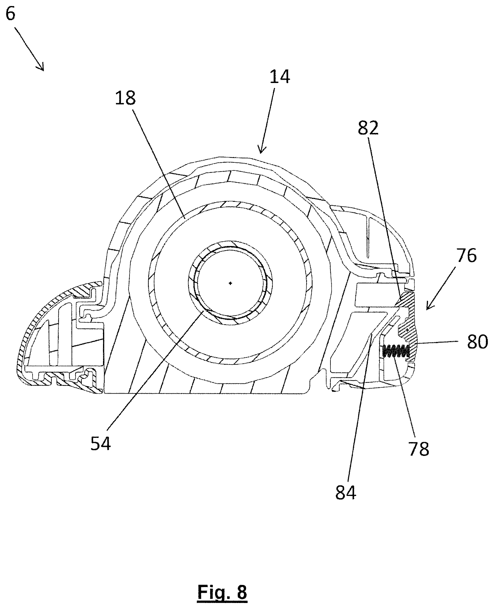
[0035] FIG. 8 is a cross sectional view of the cleaner head, taken through a narrowed waist of a spool supported on the end cap in a plane which is normal to the rotation axis of the agitator.
DETAILED DESCRIPTION OF THE DISCLOSURE
[0036] Throughout the description and drawings, corresponding reference numerals denote corresponding features.
[0037] FIG. 1 shows a vacuum cleaner 2 according to an embodiment of the invention. The vacuum cleaner 2 of this embodiment is an upright vacuum cleaner. It has a rolling assembly 4 which carries a cleaner head 6, and an `upright` body 8. The upright body 8 can be reclined relative to the head assembly 4, and includes a handle 10 for manoeuvring the vacuum cleaner 2 across the floor. In use, a user grasps the handle 10 and reclines the upright body 8 until the handle 10 is disposed at a convenient height. The user can then roll the vacuum cleaner 2 across the floor using the handle 10 in order to pass the cleaner head 6 over the floor and pick up dust and other debris therefrom. The dust and debris is drawn into the cleaner head by a suction generator in the form of a motor-driven fan (not visible) housed on board the vacuum cleaner 2, and is ducted in conventional manner under the fan-generated suction pressure to a cyclonic separating apparatus 12 where dirt is separated from the air. The relatively clean air is then exhausted back to the atmosphere.
[0038] The cleaner head 6 is shown in isolation in FIGS. 2 and 3. It has a housing 14 that defines an agitator chamber 16 within which an agitator 18 is received. The agitator 18 is generally cylindrical, and in this embodiment is hollow. It has a brush region 19 which has a pair of helical grooves 20 configured to support corresponding helical arrays of agitating bristles (not shown). The agitator chamber 16 rotatably supports the agitator 18 so that the agitator can rotate about a rotation axis 22 under action of an drive assembly (not visible). In this case, the rotation axis 22 is also the longitudinal axis of the agitator 18.
[0039] FIG. 4 shows the cleaner head 6 with the agitator 18 and part of the housing 14 removed, and FIG. 5 shows a cross section through the (complete) cleaner head 6. The rotational support and driving of the agitator will now be described with reference to these figures in combination with FIGS. 1-3.
[0040] The agitator 18 is supported for rotation by an agitator support 24 which projects into an axial end 26 of the agitator 18, and by a drive assembly 28 which projects into the opposite axial end 30 of the agitator 18. In this case, the drive assembly 28 runs along substantially the entire length of the agitator 18.
[0041] The drive assembly 28 has a spool portion 32, a support portion 34, a twin-walled support sleeve 36 which houses an electric motor 38 and gearbox 40, and a drive dog 42 which drivingly engages an end cap region 44 of the agitator 18. In use, the motor 38 is energised so as to rotate an output shaft 46, and the gearbox gears down this rotation so that the drive dog 42 (and thus the agitator 18) rotates more slowly but under greater torque. The support portion 34 comprises a bearing 48 which rotatably supports the agitator 18 via a ribbed support ring 50 that accommodates slight misalignment between the agitator 18 and drive assembly 28 and reduces the transmittal of vibration therebetween.
[0042] The agitator support 24 comprises a spool 52 which is aligned with the rotation axis 22. The spool 52 has a narrowed waist 54 positioned axially between two radially enlarged portions 56a, 56b which in this embodiment take the form of substantially annular flanges. The axial end 26 of the agitator 18 terminates in a rim 58 which is radially outward of the waist 54 and axially in line therewith.
[0043] The agitator 18 is rotatable by the drive assembly 28 in a first direction, anticlockwise when viewed along the axis 22 from the axial end 26 (in other words the agitator 18 rotates `forwards`). The grooves 20 support the helical arrays of bristles (not visible) such that they run around the agitator 18 towards the axial end 26 in the opposite direction. In other words, they run clockwise around the agitator 18 towards the axial end 26 when viewed generally from that end, in a manner akin to a `left hand` screw thread.
[0044] The direction about which the bristles (not shown) supported in the grooves 20 run around the agitator 18, in combination with the direction of rotation of the agitator 18, means that when the agitator is rotated the bristles tend to cam large debris towards the axial end 26 (as well as propelling it generally tangentially). It also encourages hair wrapped around the agitator 18 to migrate towards the axial end 26. In some cleaner heads, the equivalent axial end of the agitator is provided with a radially-extending flange positioned to prevent hair which has migrated in this way from dropping off the end of the agitator and interfering with a bearing which supports the agitator. In the present invention, however, the axial end 26 is configured to allow hair wrapped around the agitator 18 to travel axially along the axial end 26 before and slipping off the rim 58 and onto the narrowed waist 54 of the spool 52.
[0045] In this embodiment the axial end 26 is configured to allow hair to travel axially along it and drop off the rim in that it the agitator comprises a cylindrical portion 60 of reduced diameter which intersects the brush region 19 and leads to the rim 58. Hair migrating to the axial end 26 can therefore slip onto the portion 60 and then fall off the rim 58. In other embodiments, however, the axial end may be differently configured while still allowing hair to travel axially along it. For example, the agitator may have a brush region which terminates directly at a rim. In the present invention the axial end may be configured in any suitable way which does not include any feature which prevents hair from travelling along and then falling off the axial end (such as the flange described above, or a portion of increased cross sectional area).
[0046] The spool 52 is configured to retain hair which has fallen onto it from the axial end 26 of the agitator 18. The hair wraps around the narrowed waist 54, and the enlarged portions 56a, 56b retain it thereon (since once the hair has wrapped around the narrowed waist 54, the diameter of the loop formed by the hair is too small to fit over the enlarged portions 56a, 56b). In this embodiment the radially enlarged portions 56a, 56b define opposing planar side walls 62a, 62b, which are particularly effective at retaining hair on the narrowed waist 54.
[0047] In this embodiment the diameter of the narrowed waist is around 25 mm whereas the diameter of the smaller of the two radially enlarged portions 56b is around 50 mm. Accordingly, the diameters of the radially enlarged portions 56a, 56b are at least 90% larger (nearer 100% if not more) than the diameter of the narrowed waist 54. This allows an advantageously large amount of hair to wrap around the narrowed waist 54 before any individual loop of hair has a diameter large enough for it to slip over one of the radially enlarged portions 56a, 56b.
[0048] Furthermore, in this embodiment the axial length of the narrowed waist 54 is around 20 mm, i.e. around 80% of its diameter. This relatively long narrowed waist 54 again increases the amount of hair which can be held by the spool 52. As shown in FIG. 5, around 90% of the axial length of the narrowed waist 54 is received inside the agitator 18. This provides a more compact arrangement than if more of the axial length of the narrowed waist 54 was positioned outside of the agitator 18.
[0049] As well as the spool 52, the agitator support 24 comprises a bearing 64. In this case the bearing 64 is supported by the spool 52, inside the narrowed waist 54. The bearing 64 engages a stub 66 which projects axially from the axial end 26 of the agitator 18, thereby rotatably supporting the agitator 18. The bearing 64 is secured within the narrowed waist 54 by a circlip 67, but engages the stub 66 by friction alone. This allows the agitator 18 and the spool 52 to be moved relative to one another along the axis 22 so as to withdraw the spool from the agitator, as described in more detail below.
[0050] Referring now to FIGS. 6 and 7 in combination with FIGS. 1-5, the spool 52 is provided on an end cap 68 of the agitator support 24 which can be released from the housing 14 so as to open an aperture 70 therein, or attached to the housing so as to close the aperture 70. The agitator 18 can be removed from within the agitator chamber 16 and around the drive assembly 28 by sliding it axially through the aperture 70.
[0051] In this case the agitator 18 engages the support ring 50 on the bearing 48 of the drive assembly 28 through friction, and as noted above the stub 66 of the agitator 18 engages the bearing 64 on the spool 52 through friction. When the end cap 68 is removed from the housing 14, the two bearings 48, 64 move apart. Accordingly, if the frictional engagement between the bearing 64 and stub 66 is greater than that between the agitator 18 and the support ring 50, then as the end cap 68 is removed from the housing 14, the agitator 18 will come with it. The agitator 18 and end cap 68 can then be separated from one another manually. Alternatively, if the frictional engagement between the bearing 64 and stub 66 is less than that between the agitator 18 and the support ring 50 then as the end cap 68 is removed from the housing 14, the end cap 68 and agitator 18 separate from one another. The agitator 18 can then be removed from the cleaner head 6 by sliding it through the aperture 70 manually. In either case, the spool 52 can be withdrawn from the agitator 18 so that the user can easily access the narrowed waist 54 and remove hair therefrom.
[0052] In this embodiment, the end cap 68 is attachable to the housing 14 through an annular array of recesses 72 provided on the end cap 68 which are engageable with a complementary annular array of lugs 74 provided on the housing 14. To attach the end cap 68 to the housing 14, the end cap 68 is presented to the housing 14 at an angular position about the axis 22 which locates the recesses 72 and lugs 74 out of alignment with one another in the circumferential direction. This is shown in FIG. 6. The end cap 68 can then be pushed into the housing 14 along the axis 22. This moves the recesses 72 and lugs 74 into alignment in the axial direction (and pushes the bearing 64 onto the stub 66 if the agitator 18 is in the agitator chamber 16), but they remain out of alignment in the circumferential direction. The end cap 68 is then rotated about the axis 22 so as to move the recesses 72 circumferentially into alignment with the lugs 74. This positions the lugs 74 within the recesses 72, thereby preventing the end cap 68 from being pushed away from the housing 14. To detach the end cap 68 again, the above steps are reversed--the end cap 68 is rotated in the opposite direction so as to bring the apertures 72 and lugs 74 out of circumferential alignment, then the end cap and housing 14 can be pulled apart.
[0053] Referring now to FIG. 8 in combination with FIGS. 1-7, the end cap also has a pivotable latch 76 which is spring-loaded by a coil spring 78. The latch 76 has a push-button 80, and a ratchet tooth 82 that engages with a ratchet tooth 84 provided on the housing 14. As the end cap 68 is rotated about the axis 22 to position the recesses 72 around the lugs 74 as described above, the ratchet teeth 82, 84 contact one another and tooth 84 cams tooth 82 generally radially outwards. This pivots the latch 76 to allow tooth 82 to pass over tooth 84, and compresses the spring 78. When the end cap 68 has reached its final position and the lugs 74 are received in the recesses 72, the latch 76 can pivot back under the influence of the spring 78. If the end cap 68 is then urged to rotate in the opposite direction (which would disengage the recesses 72 and lugs 74), the teeth 82, 84 abut and prevent this movement. When the user wishes to rotate the end cap 68 so as to detach it from the housing, they press the push-button 80. This pivots the latch and lifts tooth 82 out of engagement with tooth 84 so that the end cap 64 can be rotated.
[0054] Referring to FIGS. 4 and 5 in particular, it is noteworthy that like the spool 52, the spool portion 32 of the drive assembly 28 has a narrowed waist 86 positioned between two radially enlarged portions 88a, 88b. The spool portion 32 therefore forms a second spool, and is configured to retain a length of hair wrapped around its narrowed waist 86. Also like the spool 52, the spool portion 32 is aligned with the axis 22. The opposite axial end 30 of the agitator 18 terminates in a rim 90, and the spool portion 32 projects into the opposite end 30 such that the rim 90 is axially in line with the narrowed waist 86. Hair wrapped around the agitator 18 can therefore fall off the rim 90 and onto the spool portion 32, wrapping around the narrowed waist 86. In this particular embodiment however, the opposite axial end 30 is not configured to allow hair wrapped around it to travel axially along it. Instead, the opposite axial end 30 has a shallow flange 92 which is arranged to block movement of hair towards the rim 90. Accordingly, if hair falls off the rim 90 it is retained on the spool portion 32, but hair is not encouraged to fall off the rim 90. The majority of the hair is therefore collected on the spool 52, from which it can be removed easily due to the spool 52 being provided on the removable end cap, while any hair which nonetheless falls off the opposite axial end is prevented from interfering with the bearing 48.
[0055] It will be appreciated that numerous modifications to the above described embodiments may be made without departing from the scope of invention as defined in the appended claims. For instance, although in the above embodiment the spool has a substantially cylindrical narrowed waist positioned between two flanges, giving it the general shape of a sewing bobbin, in one alternative the spool may have the general shape of a juggling diablo, the narrowed waist itself being hourglass-shaped and the radially enlarged portions extending outwards but tapering towards one another.
[0056] For the avoidance of doubt, the optional and/or preferred features described above may be utilised in any suitable combinations, and in particular in the combinations set out in the appended claims. Features described in relation to one aspect of the invention, may also be applied to another aspect of the invention, where appropriate.
* * * * *
D00000
D00001
D00002
D00003
D00004
D00005
D00006
D00007
D00008
XML
uspto.report is an independent third-party trademark research tool that is not affiliated, endorsed, or sponsored by the United States Patent and Trademark Office (USPTO) or any other governmental organization. The information provided by uspto.report is based on publicly available data at the time of writing and is intended for informational purposes only.
While we strive to provide accurate and up-to-date information, we do not guarantee the accuracy, completeness, reliability, or suitability of the information displayed on this site. The use of this site is at your own risk. Any reliance you place on such information is therefore strictly at your own risk.
All official trademark data, including owner information, should be verified by visiting the official USPTO website at www.uspto.gov. This site is not intended to replace professional legal advice and should not be used as a substitute for consulting with a legal professional who is knowledgeable about trademark law.