Seating Device Adaptable To Accommodate Varying Support Conditions
Newara; Timothy Andrew
U.S. patent application number 16/841497 was filed with the patent office on 2020-10-08 for seating device adaptable to accommodate varying support conditions. The applicant listed for this patent is Timothy Andrew Newara. Invention is credited to Timothy Andrew Newara.
| Application Number | 20200315356 16/841497 |
| Document ID | / |
| Family ID | 1000004807914 |
| Filed Date | 2020-10-08 |


| United States Patent Application | 20200315356 |
| Kind Code | A1 |
| Newara; Timothy Andrew | October 8, 2020 |
Seating Device Adaptable To Accommodate Varying Support Conditions
Abstract
A seating device employing an interaction of components to include an engineered multi surface rear stabilizer component comprised of a rotatable object engagement piece working in conjunction with an adjustable support piece granting the ability to lock in position by means of a binding style fastener. This multi surface rear stabilizer is mounted to one end of a two-piece sleeve type, length adjustable trunk, capable of four-sided rotation granting the center fulcrum design of the foot piece to be employed in any direction as well as the closed position. This device employs a rotatably connected seat to a swing arm style piece connected to the trunk granting the ability to incrementally adjust from parallel to perpendicular to the associated trunk.
| Inventors: | Newara; Timothy Andrew; (Montpelier, VT) | ||||||||||
| Applicant: |
|
||||||||||
|---|---|---|---|---|---|---|---|---|---|---|---|
| Family ID: | 1000004807914 | ||||||||||
| Appl. No.: | 16/841497 | ||||||||||
| Filed: | April 6, 2020 |
Related U.S. Patent Documents
| Application Number | Filing Date | Patent Number | ||
|---|---|---|---|---|
| 62830836 | Apr 8, 2019 | |||
| Current U.S. Class: | 1/1 |
| Current CPC Class: | A47C 7/60 20130101; A47C 7/004 20130101; A47C 9/10 20130101 |
| International Class: | A47C 7/60 20060101 A47C007/60; A47C 9/10 20060101 A47C009/10; A47C 7/00 20060101 A47C007/00 |
Claims
1. A seating device comprising: a trunk having a longitudinal axis, a first end, and a second end spaced from the first end along the longitudinal axis; a seat secured to the trunk by a swing arm piece (from FIG. 5) used to adjust an angle of the seat relative to the longitudinal axis of the trunk; and a multi surface engagement system (MRS1+MRS2+ALD1) (from FIG. 7) engaged with the trunk at the first end of the trunk, the multi surface engagement system including an object engagement piece (MRS1) and an engagement support piece (MRS2) (both from FIG. 7) securing the object engagement piece to the trunk in any one of a plurality of different positions relative to the trunk.
2. The seating device of claim 1, further comprising a foot stabilizer secured to the trunk at the second end of the trunk.
3. The seating device of claim 2, wherein the foot stabilizer is movably secured to the trunk.
4. The seating device of claim 3, where the foot stabilizer is a center fulcrum foot stabilizer (from FIG. 4) pivotably secured to the trunk.
5. The seating device of claim 1, wherein the seat has a central pivot point rotatable three hundred and sixty degrees secured to the swing arm piece (FIG. 5).
6. The seating device of claim 1, wherein the trunk comprises an outer trunk piece (FIG. 2) providing the first end and an inner trunk piece (FIG. 3) providing the second end.
7. The seating device of claim 6, wherein the inner trunk piece (FIG. 3) is slidably engaged within the outer trunk piece (FIG. 2).
8. The seating device of claim 1, wherein the object wherein the object engagement piece (MRS1) (from FIG. 7) has a V-shape and is rotatably secured to the engagement support piece (MRS2) (from FIG. 7) so as to trace out a frustum of a cone when rotated.
9. A seating device as shown in any one or more of the drawings of this disclosure.
10. A seating device as disclosed herein employing the multi surface engagement system (MRS1+MRS2+ALD1) (from FIG. 7).
Description
CROSS-REFERENCE TO RELATED APPLICATIONS
[0001] This application claims priority of application No. 62/830,836 filed 2019 Apr. 8
STATEMENT REGARDING FEDERALLY SPONSORED RESEARCH OR DEVELOPMENT
[0002] Not Applicable
REFERENCE TO SEQUENCE LISTING, A TABLE, OR A COMPUTER PROGRAM LISTING COMPACT DISK APPENDIX
[0003] Not Applicable
FIELD OF THE INVENTION
[0004] The seating device of the present disclosure represents a device engineered with specific features to adapt to the obstacles that occur as a result of the constant changes and diverse conditions in nature that affect the quality and success of outdoor experiences.
BACKGROUND OF THE INVENTION
[0005] Seating devices are currently available on the market that contain many deficits regarding adaptation to the natural environment that the present disclosure overcomes. Currently available devices are unable to accommodate compound angles at both the seat and foot ends while simultaneously adapting to size, unusual surface features, and composition complexities of the immediate environment.
[0006] A need therefore exists for a device capable of adapting to the combination of unique features presented by the natural environment.
SUMMARY OF THE INVENTION
[0007] In this embodiment, the overall length of the seating device both at the minimum and maximum extensions may be based on the height of a typical user, such as a six-foot adult. At its maximum extension, the seating device can accommodate a near-standing position while maintaining a comfortable seat angle. The minimum position achievable may allow the seating device to rest just inches from the most horizontal surface and provide increments that include a standard chair height, again while maintaining a comfortable seat angle.
[0008] In this embodiment, the resulting exposed section of the inner trunk piece when the device is at its minimal position dictates the full length of the center fulcrum foot stabilizer. This length is equal to the width of the object engagement piece of the multi surface rear stabilizer. It is designed to symmetrically distribute and balance the weight between the top and bottom of the seating device.
[0009] In this embodiment, the length of the swing arm may be determined by taking into consideration the necessary measurement to place center mass of the user a comfortable distance from a potential backrest while maintaining a rear leaning center of gravity on the device. In the full horizontal adaptation this places the user equidistant between the front and rear points of contact with the surface allowing for a center balanced three-hundred-and-sixty-degree rotation of the seat.
[0010] In this embodiment, the depth of the seat may be determined by the overall width of the object engagement piece of the multi surface rear stabilizer. It is designed to the maximum width of the total device when in its compact travel position. The width of the center pivot seat was determined by doubling the measurement from the pivot point of the seat attachment on the swing arm to the lower edge of the outer trunk piece.
[0011] In this embodiment, the overall length of the engagement support piece of the multi surface rear stabilizer was determined by taking into account the length necessary for this piece to adjust fully on its pivot point and freely clear the swing arm component in addition to the length necessary to allow clearance between the fastening hardware that secures it to the object engagement piece and the upper trunk piece at the other end. Consideration of length was also made to properly place the center mass of the user an appropriate distance from a potential backrest.
[0012] In this embodiment, the center fulcrum foot stabilizer is designed so that it can achieve angles anywhere from parallel with the inner trunk piece all the way to one hundred thirty-five degrees. This design allows the piece to adapt to uneven ground, as well as to things like rocks and roots that may be in the way.
[0013] One common example would be near the base of just about every tree in nature. The roots radiate from the trunk at varying sizes and depths. Utilizing the center fulcrum foot stabilizer, the inner trunk piece can be placed on the ground next to, and on either side of these roots, while automatically adjusting by creating an angle that applies pressure evenly on the high point and low point by way of the center pivot of the center fulcrum foot stabilizer.
[0014] In this embodiment, if space is narrow and linear, the inner trunk piece can be removed and rotated to four different positions to allow the center fulcrum foot stabilizer to run parallel with the available space while still utilizing the full length of the foot at all angles.
[0015] In unique cases wherein a surface presents the opportunity for only a minimal footprint, the center fulcrum foot stabilizer can be closed to the parallel position with the inner trunk piece to create a narrow point that provides a secure footing between the surface features.
[0016] In the robust version of the embodiment being described, the C channel design of the center fulcrum foot stabilizer lends great stability to the device whether there is a hard surface or conditions of deep foliage, pine needles, or sand. In its design, one side is always flat while the other has two deep edges backed by a flat face. With these two features employed adaptability is enhanced.
[0017] In horizontal use of the seating device, the center fulcrum foot stabilizer, being of equal width to the object engagement piece and perpendicular to the inner trunk piece, stability is created by making contact with the surface at an equal distance from center at both ends and placing opposing pressure at four corners.
[0018] When the inner trunk piece contains evenly spaced adjustment holes reflective of one another on all four sides, this piece has the ability to rotate three hundred and sixty degrees, by ninety-degree increments, to change the orientation of the center fulcrum foot stabilizer. This adjustment can also be made at all increments of the trunk extension between the inner trunk piece and the outer trunk piece. These holes lend the ability to incrementally adjust the height of the center pivot seat from sitting flat to almost a full stand, including within a standard chair height. This component was designed for comfort and durability in mind.
[0019] Noting that sitting parallel with the ground is one of the most important aspects of remaining comfortable for any amount of time, in this embodiment, the entirety of the seat angle adjustment system hinges on a single axis. This design defines strength through simplicity. By utilizing evenly spaced holes along the lower edge of the swing arm, the stress is distributed between two very solid points. This design also allows for a full parallel to perpendicular arrangement of the center pivot seat making it useful in all situations.
[0020] In this embodiment, the position of the center pivot seat on the swing arm not only balances the weight of the user versus the object against which the seating device is engaging, it also places the user the correct distance from the object so that the object may be used as a backrest.
[0021] The center pivot of the seat lends the ability to smoothly and silently rotate from right to left all the while absent of any upper body movement or weight redistribution. This can greatly minimize the body movement necessary to alter your field of view or body orientation and minimizes noise generated therefrom.
[0022] The freedom of rotation employed by the multi surface engagement system provides the ability to engage any surface at the optimal angle for stability and silence. This includes any abnormality in tree shape all the way to ledges and vertical fissures in rock. It always adjusts to find the optimal angle.
[0023] In this embodiment, the engagement support piece employs an angle locking device to apply clamping pressure to fix the piece at the selected angle. This angle works in conjunction with the orientation of the trunk component (e.g. outer plus inner trunk pieces) to the object or surface and with the seat angle adjustment system to allow a comfortable horizontal seat angle for any combination of situations.
[0024] The many adjustment features of the multi surface rear stabilizer removes any challenges presented by an ever-changing natural environment.
BRIEF DESCRIPTION OF DRAWINGS
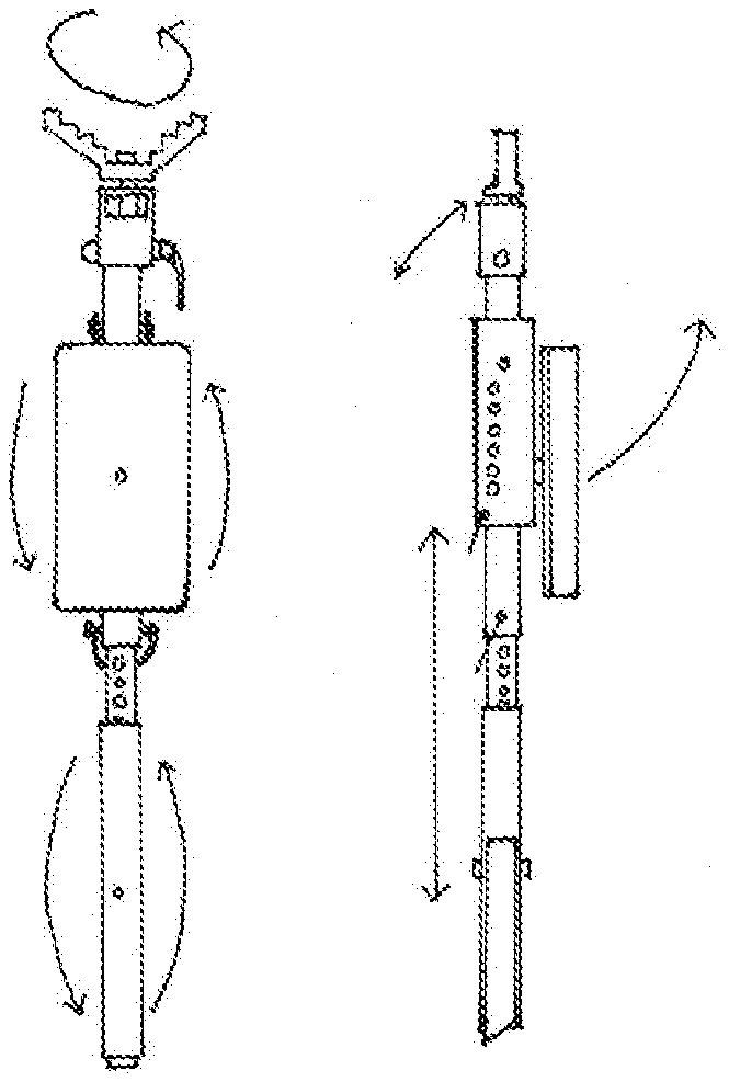
[0025] FIG. 1 from left to right is a front view and a side view of the device.
[0026] FIG. 2 is a perspective view of the outer trunk piece.
[0027] FIG. 3 is a perspective view of the inner trunk piece.
[0028] FIG. 4 following top to bottom is a side view, and top view of the center fulcrum foot stabilizer.
[0029] FIG. 5 is a perspective view of the swing arm component.
[0030] FIG. 6 from left to right to bottom a side view and top view of the center pivot seat, and top view of the foam pad component of center pivot seat.
[0031] FIG. 7 is a front view of the multi surface adjustable rear stabilizer.
DETAILED DESCRIPTION OF THE INVENTION
[0032] The components of the most robust example of the seating device are described below in detail. Those skilled in the art will readily appreciate that the seating device detailed immediately below is merely one example of many seating devices that can be made using one or more of the unique features disclosed herein.
[0033] Referring to FIG. 1 a front view and side view displays the assembled seating device made in accordance with aspects of the present disclosure.
[0034] Referring to FIG. 2 the outer trunk piece (T1) comprises a square tube that has three pass-through holes. The top hole (H1) provides a pass-through hole that corresponds with the holes (H13) of the multi-surface rear stabilizer transition bracket (MRS2) (from FIG. 7) that align in such a way to allow the angle locking device (ALD1) (from FIG. 7) to pass through both pieces and be tightened causing them to be in a fixed position.
[0035] The second hole (H2) provides a pass-through hole that aligns with the swing arm holes (H5) (from FIG. 5) allowing the swing arm to pivot on a fulcrum from this point in relation to the outer trunk piece.
[0036] The third hole (H3) provides a pass through to work in combination with the height adjustment holes (HAH) of the inner trunk piece (T2) (from FIG. 3) to adjust the length of the combined trunk piece.
[0037] Referring to FIG. 3 the inner trunk piece (T2) comprises a square tube designed to conformally fit within and slide inside the outer trunk piece (from FIG. 2) with minimal tolerance. It contains evenly spaced height adjustment holes (HAH) reflective of one another on all four sides covering one half of its total length. These holes work in conjunction with hole (H3) from the outer trunk piece (T1) (from FIG. 2) to secure both trunk pieces in a fixed position to a fixed length.
[0038] The height adjustment holes (HAH) of the inner trunk piece (T2) being reflective of one another on all four sides allows it to be removed from the outer trunk piece (T1) (from FIG. 2) and rotated to show each of the four faces in the forward position according to necessity. This also allows the center-fulcrum foot stabilizer (FS1) (from FIG. 4) that is mounted to the lower section of the inner trunk piece (T2) the option of all four directions.
[0039] In this embodiment, the lower section of the inner trunk piece (T2) has an angle of forty-five degrees to provide a single side cutting edge for contact with the substrate of the chosen location. The lower section of the inner trunk piece (T2) contains a hole (H4) through two sides measuring to the center of the lower section of the inner trunk piece allowing connection to the center fulcrum foot stabilizer (FS1) (from FIG. 4).
[0040] Referring to FIG. 4 the center fulcrum foot stabilizer is comprised of a square tube dimensionally sized to fit over the inner trunk piece (from FIG. 3) with minimal resistance.
[0041] The length of the center fulcrum foot stabilizer is sized to cover the lower section of the inner trunk piece (T2) (from FIG. 3) while not impeding on the outer trunk piece (T1) (from FIG. 2) section when the outer trunk piece and the inner trunk piece are locked in the overall minimum length position. Starting from its center point, the center fulcrum foot stabilizer has, on opposing sides and the full width across, a section removed measuring twice the width of the inner trunk piece.
[0042] Centered on the remaining faces of this section is a hole to accept the mounting hardware which passes through center fulcrum foot stabilizer and holes (H4) of the lower section of the inner trunk piece (T2) (from FIG. 3), creating a fulcrum on which the center fulcrum foot stabilizer (FS1) can pivot.
[0043] The remaining lengths of the square tubing of the center fulcrum foot stabilizer on either side of the removed center section shall have one face of full width on opposing sides removed creating opposing "C" channels, allowing the center fulcrum foot stabilizer to pivot to a complete parallel with the inner trunk piece on one side and a greater angle on the other. This allows the inner trunk piece (T2) (from FIG. 3) to rest inside of the center fulcrum foot stabilizer and to a perpendicular position as well.
[0044] Referring to FIG. 5 the swing arm comprises a rectangular tube, here sized one point five times the width of outer trunk piece (T1) (from FIG. 2) on its wider faces and opposing faces have inside dimensions sized to fit over the outside dimensions of the outer trunk piece (T1) (from FIG. 2) with minimal resistance. One face of the shorter dimension is removed to create a "C" channel.
[0045] At one end of the remaining shorter dimension face, a section is removed measuring full width by a length of one point two five times that of the outer dimension of the outer trunk piece, allowing it to pivot from parallel to perpendicular relative to outer trunk piece (T1) (from FIG. 2).
[0046] At the same end but on the wider faces is a hole (H5). This hole (H5) is centered on the wider face and from the end is centered on the removed portion of the shorter dimension. This hole (H5) will accept the mounting hardware to pass through the swing arm (SA1) and correspond with hole (H2) located on the outer trunk piece (T1) (from FIG. 2), creating a pivot point for the swing arm (SA1) to hinge on the outer trunk piece (T1) (from FIG. 2).
[0047] There are evenly spaced holes (H6) running the length of the swing arm (SA1), here along a centerline located from the open edge of the wide face by a distance of one third the total width. These holes (H6) are present on both legs of the U-shaped transverse cross section of the swing arm to allow for the through-insertion of fastening hardware that will rest on the outer trunk piece (T1) (from FIG. 2) as the swing angle of the swing arm (SA1) is adjusted.
[0048] On the same two faces is also a hole (H7) located at the opposite end as hole (H5). In this example, these holes (H5, H7) are centered at one quarter of the total dimension of the wide face as measured from the open edge as well as the end. Hole (H7) will accept through insertion of hardware and will not interfere with the outer trunk piece when the outer trunk piece (T1) (from FIG. 2) and the swing arm (SA1) are in the parallel position relative to one another.
[0049] On the remaining narrower dimensioned face of the swing arm, and at the opposite end of where a section was removed, is a hole (H8). In this example, this hole (H8) is centered on the face and measures one quarter of the total length of (SA1) away from the solid end of this face. This hole (H8) will accept mounting hardware to attach the center pivot seat (CPS1) (from FIG. 6) using the corresponding hole (H9) from the center pivot seat.
[0050] Referring to FIG. 6 the center pivot seat measures six inches wide by twelve inches long and has a hole (H9) centered on both length and width to allow mounting hardware to pass through along with corresponding hole (H8) from the swing arm (SA1) (from FIG. 5) connecting the swing arm (SA1) and the center-pivot seat on a pivot point.
[0051] In this example, attached to one face of the center-pivot seat (CPS1) is a foam pad (CPS2) of equal length and width to that of the center-pivot seat (CPS1). This pad (CPS2) has one hole (H10) centered on both width and length to allow mounting hardware for the center pivot seat (CPS1) to pass through.
[0052] Referring to FIG. 7 an example multi surface adjustable rear stabilizer is illustrated. In this example, the multi-surface adjustable rear stabilizer consists of three components, an object engagement piece (MRS1) and an engagement support piece (MRS2), which together are connected by mounting hardware and an angle locking device (ALD1) to the outer trunk piece (T1) (from FIG. 2).
[0053] In this example, the object engagement piece (MRS1) is constructed of an open V-shaped portion having a center portion approximately twice the thickness of each arm and that measures one third the total width of the V-shaped portion. Located at the center of the V-shape and centered on its width is a hole (H11) to allow mounting hardware (not labeled) to pass through and connect together the object engagement piece (MRS1) and the engagement support piece (MRS2).
[0054] In the embodiment shown, the inside surface of the V-shaped portion has a zig-zag tooth design. These teeth may be absent immediately near (H11) to allow the object engagement piece (MRS1) to rotate a full three hundred and sixty degrees without imposition of associated hardware.
[0055] The engagement support piece (MRS2) is coupled to the object engagement piece (MRS1) at one end and to the outer trunk piece (T1) (from FIG. 2) at the other end.
[0056] In this example, the engagement support piece (MRS2) comprises a square tube that is closed at one end and is sized to fit over the outer trunk piece (T1) (from FIG. 2) plus hardware with minimal resistance. In the present embodiment, the length of the engagement support piece (MRS2) is two and half times the width of the outer trunk piece (T1) (from FIG. 2). One face of the engagement support piece (MRS2), starting at the closed end, has been removed by its full length and width. The opposing face (starting at the closed end) has two thirds of the face removed by full width. This leaves a one-third section of that face that when installed will be on the same side of the outer trunk piece (T1) (from FIG. 2) as the center pivot seat (CPS1) (from FIG. 6).
[0057] The closed end has a hole (H12) centered on the square to accept fastening hardware (not labeled) connecting the engagement support piece (MRS2) to the object engagement piece (MRS1).
[0058] On the remaining full-length intact faces is a hole (H13) centered on its width and measuring a distance from the open end of the engagement support piece (MRS2) equal to one third the overall length of the engagement support piece (MRS2). This hole (H13) is sized to accept the pass-through of the angle locking device (ALD1). The engagement support piece (MRS2) will be engaged over the outer trunk piece (T1) (from FIG. 2), aligning holes (H13) from the engagement piece support (MRS2) and holes (H1) from the outer trunk piece (T1) (from FIG. 2). The angle locking device (ALD1) passes through both sets of holes connecting together the engagement support piece (MRS2) and the outer trunk piece (T1) (from FIG. 2).
[0059] Still referring to FIG. 7 the angle locking device (ALD1) may be a quick-release type of binder clamp bolt of appropriate length to pass through holes (H13) of engagement support piece (MRS2) and holes (H1) of the outer trunk piece (T1) (from FIG. 2) and function as designed to apply clamping pressure to hold these pieces at a selected angle.
[0060] There are less robust versions composed of varying mixtures of alternative versions of each component that can be made without departing from the scope and intent of the present disclosure. The embodiment just described characterizes a robust version of the device.
* * * * *
D00000
D00001
D00002
D00003
D00004
XML
uspto.report is an independent third-party trademark research tool that is not affiliated, endorsed, or sponsored by the United States Patent and Trademark Office (USPTO) or any other governmental organization. The information provided by uspto.report is based on publicly available data at the time of writing and is intended for informational purposes only.
While we strive to provide accurate and up-to-date information, we do not guarantee the accuracy, completeness, reliability, or suitability of the information displayed on this site. The use of this site is at your own risk. Any reliance you place on such information is therefore strictly at your own risk.
All official trademark data, including owner information, should be verified by visiting the official USPTO website at www.uspto.gov. This site is not intended to replace professional legal advice and should not be used as a substitute for consulting with a legal professional who is knowledgeable about trademark law.