Push Broom Head And Method Of Fabrication Thereof
BERROUARD; Mathieu
U.S. patent application number 16/834962 was filed with the patent office on 2020-10-08 for push broom head and method of fabrication thereof. The applicant listed for this patent is GARANT GP. Invention is credited to Mathieu BERROUARD.
| Application Number | 20200315335 16/834962 |
| Document ID | / |
| Family ID | 1000004738263 |
| Filed Date | 2020-10-08 |


| United States Patent Application | 20200315335 |
| Kind Code | A1 |
| BERROUARD; Mathieu | October 8, 2020 |
PUSH BROOM HEAD AND METHOD OF FABRICATION THEREOF
Abstract
A push broom head comprising a base with a leading edge and a trailing edge separated by a width of the base; and tufts of bristles extending from a surface of the base; the tufts of bristles being arranged in rows of bristles of decreasing stiffness from the leading edge to the trailing edge of the base, with a leading row of very stiff bristles and a trailing row of bendable bristles, thereby combining increased ease of handling by a user for an efficient sweeping action, the leading rows loosening and moving heavier particles and the trailing rows loosening and moving finer particles not acted upon by the stiff leading rows.
| Inventors: | BERROUARD; Mathieu; (Levis, CA) | ||||||||||
| Applicant: |
|
||||||||||
|---|---|---|---|---|---|---|---|---|---|---|---|
| Family ID: | 1000004738263 | ||||||||||
| Appl. No.: | 16/834962 | ||||||||||
| Filed: | March 30, 2020 |
Related U.S. Patent Documents
| Application Number | Filing Date | Patent Number | ||
|---|---|---|---|---|
| 62829248 | Apr 4, 2019 | |||
| Current U.S. Class: | 1/1 |
| Current CPC Class: | A46D 1/0207 20130101; A46D 1/08 20130101; A46B 9/06 20130101; A46B 9/025 20130101; A46B 2200/302 20130101; A46D 3/00 20130101 |
| International Class: | A46B 9/06 20060101 A46B009/06; A46D 1/00 20060101 A46D001/00; A46B 9/02 20060101 A46B009/02; A46D 1/08 20060101 A46D001/08; A46D 3/00 20060101 A46D003/00 |
Claims
1. A push broom head, comprising: a base, the base comprising a leading edge and a trailing edge separated by a width of said base; and tufts of bristles extending from a surface of the base; wherein said tufts of bristles are arranged in rows of bristles of decreasing stiffness from said leading edge to said trailing edge of the base.
2. The push broom head of claim 1, wherein said rows of bristles of decreasing stiffness from said leading edge to said trailing edge comprise leading rows and trailing rows, a ratio of the rigidity of the bristles of the leading rows over the rigidity of the bristles of the trailing rows being selected in a range between 10 and 20.
3. The push broom head of claim 1, wherein said tufts of bristles comprise bristles in any one of: PE, PET, PP, PVC and a combination thereof.
4. The push broom head of claim 1, comprising, arranged in rows of bristles of decreasing stiffness from said leading edge to said trailing edge of the base: at least two leading rows, said at least two leading rows being offset along a length of the base; and a trailing row; a ratio of the rigidity of the bristles of the leading rows over the rigidity of the bristles of the trailing row being selected in a range between 10 and 20.
5. The push broom head of claim 1, wherein said rows of bristles of decreasing stiffness from said leading edge to said trailing edge comprise leading rows, middle rows and trailing rows, the bristles of the leading rows having a rest angle of at moist 10.degree., the bristles of said middle rows having a rest angle of about 1.degree.; and the bristles of said trailing rows having a rest angle of at most -10.degree..
6. The push broom head of claim 1, wherein the bristles of the trailing rows are flagged.
7. The push broom head of claim 1, wherein said rows of bristles of decreasing stiffness from said leading edge to said trailing edge comprise leading rows, middle rows and trailing rows, said push broom head further comprising additional tufts of bristles between the middle rows and the trailing rows, said additional tufts of bristles having a stiffness smaller than the stiffness of the bristles of the trailing rows.
8. The push broom head of claim 1, wherein the bristles of said leading rows amount for about 1/3 of a number of tufts of the broom head.
9. A push broom head, comprising a base having a leading edge and a trailing edge separated by a width; said base supporting tufts of bristles; wherein said tufts of bristles are arranged in rows of bristles; said rows comprising at least one leading row of bristles of a first stiffness and at least one trailing row of bristles of a second stiffness, said first stiffness being greater than said second stiffness.
10. The push broom head of claim 9, wherein said first stiffness is between 10 and 20 times larger than said second stiffness.
11. The push broom head of claim 9, wherein said bristles of the first stiffness have rest angles of at most 10.degree. and said bristles of the second stiffness have rest angles of at most -10.degree..
12. The push broom head of claim 9, wherein said tufts of bristles comprise bristles of any one of: PE, PET, PP, PVC and a combination thereof.
13. The push broom head of claim 9, further comprising rows of bristles of a third stiffness between said leading row and said trailing row, said third stiffness being smaller than said first stiffness and larger than said second stiffness, and.
14. The push broom head of claim 9, further comprising rows of bristles of a third stiffness between said leading row and said trailing row, said third stiffness being smaller than said second stiffness.
15. A method for making a push broom head, comprising: providing a base having a leading edge and a trailing edge; and securing, from the leading edge to the trailing edge of the base, a leading row of bristles of a first stiffness and a trailing row of bristles of a second stiffness, the first stiffness being between 10 and 20 times larger than the second stiffness.
16. The method of claim 15, comprising securing, from the leading edge to the trailing edge of the base, a first leading and a second leading rows of bristles, the second leading row being offset relative to the first leading row along a length of the base; and a trailing row of bristles of a stiffness between 10 and 20 times smaller than a stiffness of the first and second leading rows.
17. The method of claim 15, comprising securing, from the leading edge to the trailing edge of the base, a leading row of bristles of a first stiffness, a trailing row of bristles of a second stiffness, and rows of bristles of a third stiffness between the leading row and the trailing row.
18. The method of claim 15, comprising further securing a handle on the base.
19. The method of claim 15, comprising securing, from the leading edge to the trailing edge, at least two leading rows and a trailing row, wherein the bristles of the leading rows amount for about 1/3 of a number of tufts of the broom head.
20. The method of claim 15, comprising securing, from the leading edge to the trailing edge, leading rows of a first stiffness, trailing rows of a second stiffness, and middle rows of a third stiffness between the leading and trailing rows, wherein the first stiffness is selected between 10 and 20 times larger than the second stiffness and between 1.5 and 20 times larger than the third stiffness.
Description
CROSS REFERENCE TO RELATED APPLICATIONS
[0001] This application claims benefit of U.S. provisional application serial No. U.S. 62/829,248, filed on Apr. 4, 2019. All documents above are incorporated herein in their entirety by reference.
FIELD OF THE INVENTION
[0002] The present invention relates to push brooms. More precisely, the present invention relates to a push broom head and a method of fabrication thereof.
BACKGROUND
[0003] Different types of push brooms typically apply to different types of anticipated particles to be swept and to different types of sweeping surfaces, based on the fact that different type of bristles removing different types of particles depending on the sweeping surface.
[0004] Some broom heads combine bristles of different stiffness so as to efficiently remove a range of particles in one operation with a single broom. It has been found that coarse forward bristles are efficient in sweeping heavy particles while rear less coarse bristles take up finer materials that are not picked up by the coarser front bristles.
[0005] A number of configurations for broom heads were presented, including for example finer-bristled, softer border with a coarse, stiffer center section; or coarser front bristles and longer, finer rear bristles.
[0006] There is still a need in the art for a push broom head and a method of fabrication thereof.
SUMMARY OF THE INVENTION
[0007] More specifically, in accordance with the present invention, there is provided a push broom head, the push broom head comprising a base, the base comprising a leading edge and a trailing edge separated by a width of the base; and tufts of bristles of a same free length extending from a surface of the base; wherein the tufts of bristles are arranged in rows of bristles of decreasing stiffness from the leading edge to the trailing edge of the base.
[0008] There is further provided a method for making a push broom head, the method comprising providing a base having a leading edge and a trailing edge; and securing rows of bristles of decreasing stiffness from the leading edge to the trailing edge of the base.
[0009] Other objects, advantages and features of the present invention will become more apparent upon reading of the following non-restrictive description of specific embodiments thereof, given by way of example only with reference to the accompanying drawings.
BRIEF DESCRIPTION OF THE DRAWINGS
[0010] In the appended drawings:
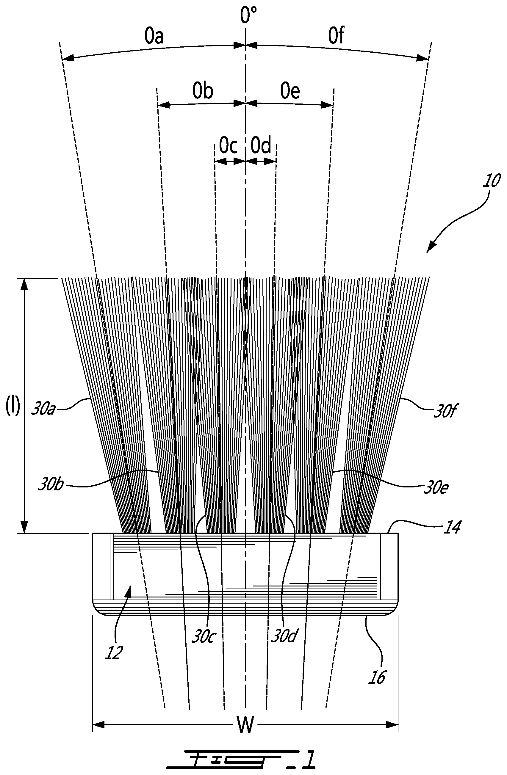
[0011] FIG. 1 is a side view of a broom head at rest according to an embodiment of an aspect of the present disclosure;
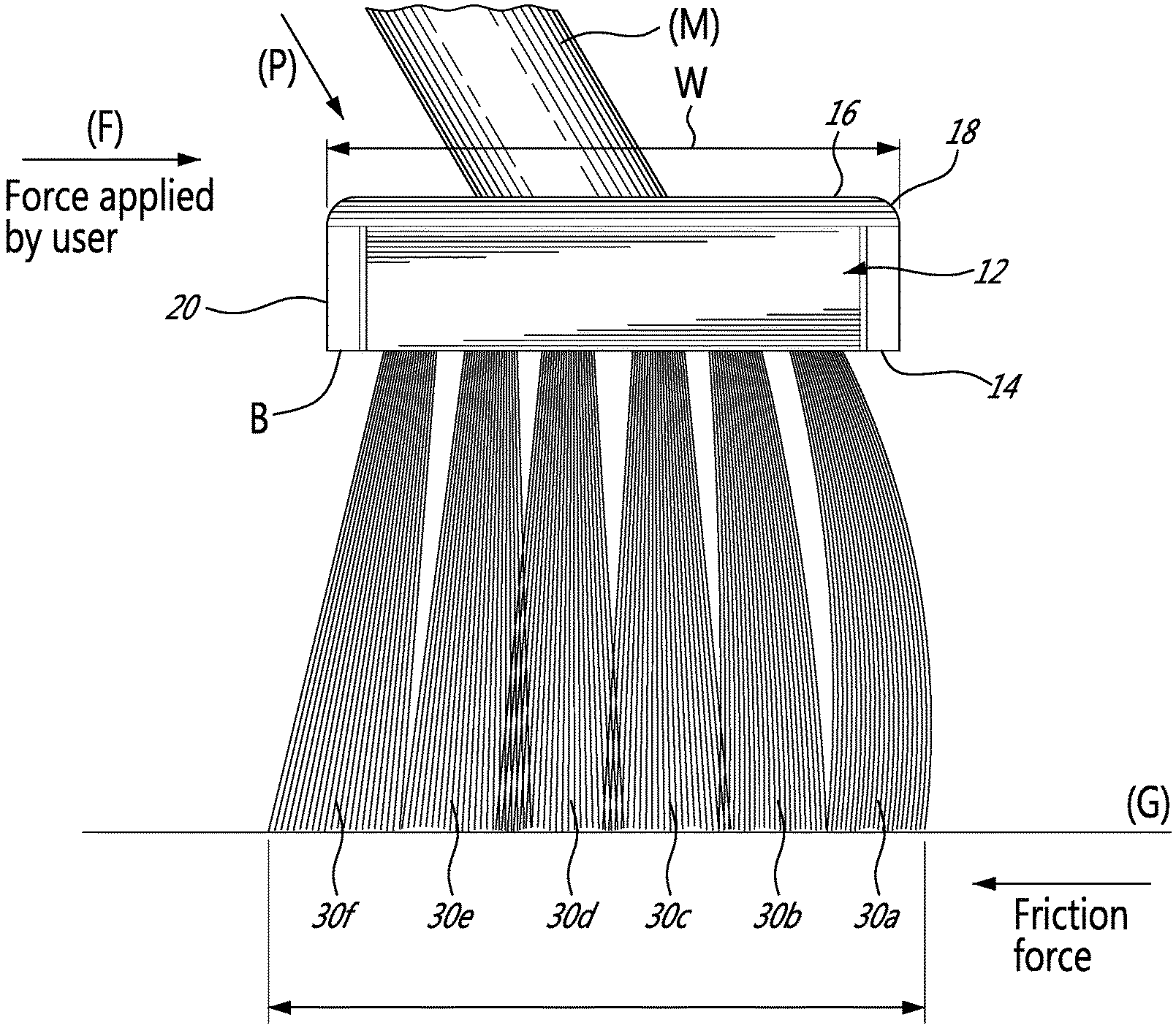
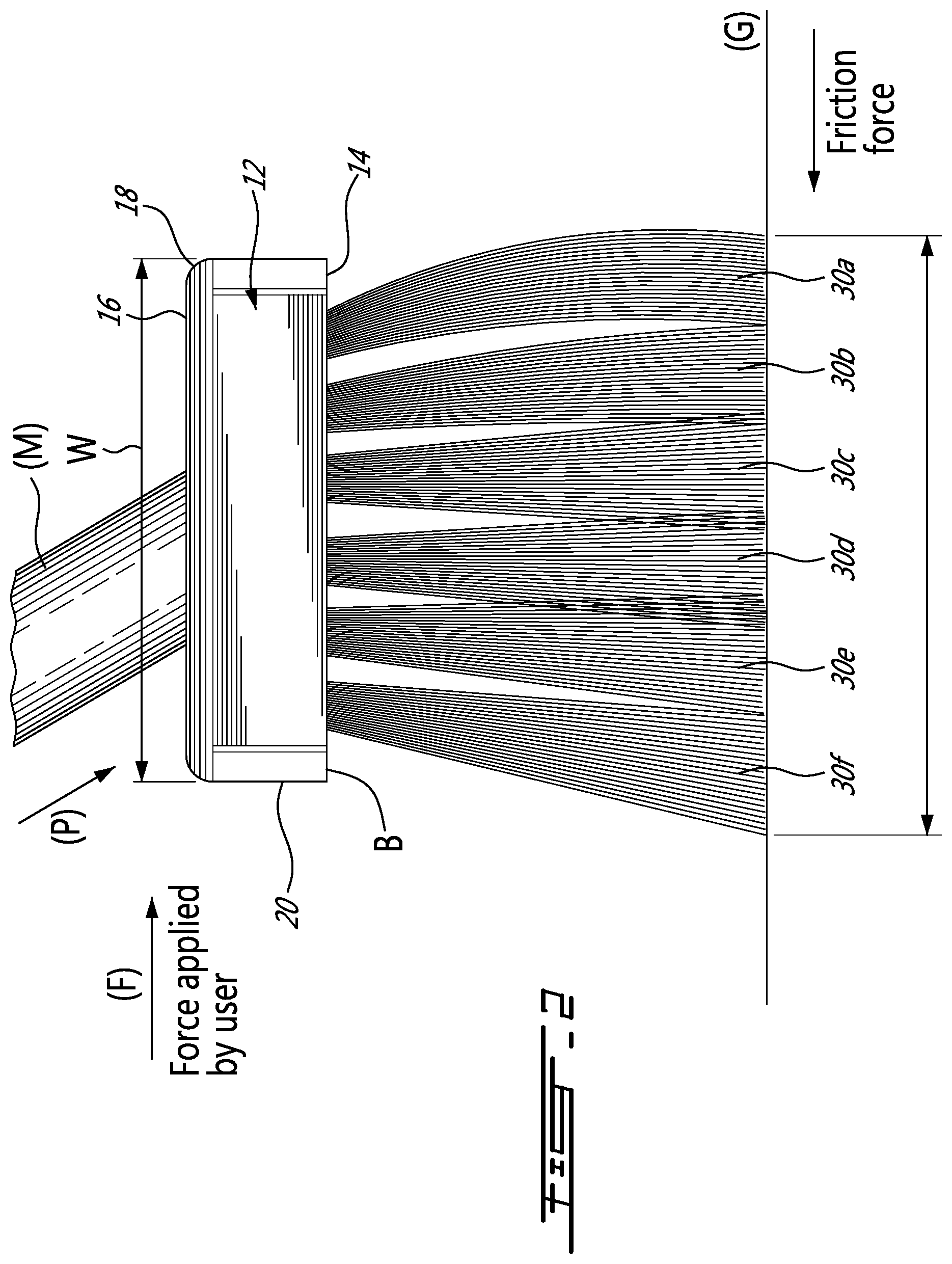
[0012] FIG. 2 is a side view of a broom head at rest according to an embodiment of an aspect of the present disclosure in use;
[0013] FIG. 3 is a bottom view of a broom head base according to an embodiment of an aspect of the disclosure;
[0014] FIG. 4 shows a test to assess stiffness of bristles; and
[0015] FIG. 5 shows a test to assess stiffness of bristles.
DESCRIPTION OF EMBODIMENTS OF THE INVENTION
[0016] The present invention is illustrated by the following non-limiting examples.
[0017] A broom head 10 as illustrated for example in FIGS. 1 and 2, comprises a base 12 having an upper surface 16 and a lower surface 14, the lower surface 14 facing a surface to be swept in normal use. The base 12 has a central vertical axis (V), and may be connected at a distal end of a handle (H) (not shown in FIG. 1) for use by an operator. The base 12 has a leading edge 18 and a trailing edge 20 separated by a width W.
[0018] The base 12 supports bristles or tufts of bristles extending from the surface facing a surface to be swept in normal us, i.e. the lower surface 14 in the present example.
[0019] In embodiments illustrated herein, tufts of bristles are arranged in rows generally parallel to the leading edge 18 and the trailing edge 20 of the base 12.
[0020] In FIG. 1, tufts 30a-30f are made of bristles of a same free length (I) from the lower surface 14 of the base 12 to their free end. The bristles may be in PE, PET, PP or PVC for example.
[0021] The central lines of the rows are extrapolated by dashed lines in FIG. 1 outwardly from their respective bristle free ends to show rest angles .theta. relative to the central vertical axis (V) of the base 12. The rest angles indicate the inclination of the tufts from the central vertical axis (V) when no pressure is applied thereto, i.e. typically when the broom head is at rest and not being used against a surface to be swept.
[0022] Leading rows, referring to rows positioned closest to the leading edge 18 of the base 12, for example within the first third of the width W of the base 12 from the leading edge 18, comprise rows of tufts 30a and 30b of very stiff bristles. For example, PVC bristles of a diameter 0.060'' for a length of 2.9', with rest angles .theta.a of about 9.degree., and .theta.b of about 6.degree. respectively are selected. At least two leading rows a and b of very stiff tufts are used, and they are offset along the length L of the base 12 (see .DELTA. in FIG. 3 for example) in such a way that the tufts of the two rows are not aligned in the direction of the width W of the base 12 so that the pair of rows of very stiff bristles together form a generally continuous barrier of very stiff bristles on the leading edge of the broom head.
[0023] Middle rows immediately downstream of the leading rows from the leading edge of the base, i.e. for example within the middle third of the width W of the base 12, comprise tufts 30c and 30d of bristles having a smaller stiffness that the leading rows, such as for example PET bristles of a diameter of about 0.029'' for the same length (I) of 2.9', with rest angles .theta.c of about 1.degree., and .theta.d of about 1.degree. respectively.
[0024] A trailing row, i. e closest the trailing edge 20 of the base 12, comprise tufts of bristles 30f having a still smaller stiffness, for example PET bristles of a diameter of about 0.018'' for a length of 2.9', with a rest angle .theta.f of about -9.degree.. The bristles of the tufts 30d may be flagged, for increased picking up efficiency of finer particles such as dust fine.
[0025] Additional tufts 30e may be provided between the middle rows and the trailing row, for picking up finer particles such as dust or sand. The additional tufts of bristles 30e may have a stiffness smaller than the tufts of bristles of the trailing row, for example PET bristles of a diameter of about 0.014'' for a length (l) of 2.9.degree., with rest angle .theta.e of about -6.degree.. At a constant diameter and free length and type of material, these bristles of tufts 30e may be crimped.
[0026] Table I summarizes such arrangement
TABLE-US-00001 TABLE I Inclination .theta. relative to the base PET bristles length O stiffness of the brush head First and second 2.9'' .060'' ++ 9.degree., 6.degree., leading rows a-b Middle rows c-d 2.9'' .029'' - 1.degree., 1.degree. row e 2.9'' .014'' (crimped) - -6.degree. Trailing row f 2.9'' .018'' (flagged) - -9.degree.;
[0027] Stiffness, also referred herein as rigidity, may be characterized by the deformation of bristles when submitted to a force, as shown in FIGS. 4 and 5 for example, and Table II below:
TABLE-US-00002 TABLE I Applied Deformation D Deformation rows force (N) (po) D/applied Force a and b 0.1161504 0.016 0.137752431 c and d 0.1161504 0.0355 0.305638207 e 0.0244269 0.1185 4.851209118 f 0.1161504 0.25 2.15238174
[0028] The rigidity (stiffness) may be obtained as the ratio of the applied load over deformation. Under a same load, the deformation of the bristles of the leading rows (a, b) is 0.016 po as opposed to 0.25 po for the bristles of the trailing row (f); yielding a ratio of the rigidity of the bristles of the leading rows (a, b) over the rigidity of the bristles of the trailing row (f) of 0.25/0.016=15.6, meaning that the rigidity of the bristles of the leading rows is 15.6 times larger than the rigidity of the bristles of the trailing row. The ratio of the rigidity of the bristles of the leading rows (a, b) over the rigidity of the bristles of the middle rows (c, d) is 0.0355/0.016=2.2, meaning that the rigidity or stiffness of the bristles of the leading rows is 2.2 times larger than the rigidity of the bristles of the middle rows. The ratio of the rigidity of the bristles of the middle rows (c, d) over the rigidity of the bristles of the trailing row (f) of 0,25/0.0355=7, meaning that the rigidity of the bristles of the middle rows (c, d) is 7 times larger than the rigidity of the bristles of the trailing row (f).
[0029] The ratio of the rigidity of the bristles of the bristles of the trailing row (f) over the rigidity of the additional row (e) may be obtained as 4,8512/2,152 (see last column of Table II)=2.27 meaning that the rigidity of the bristles of the of the trailing row the trailing row (f) is 2.27 times larger than the rigidity of the bristles of the additional row (e).
[0030] According to an embodiment of an aspect of the present disclosure, a ratio of the rigidity of the bristles of the leading rows over the rigidity of the bristles of the trailing row is selected in a range between about 10 and about 20. The ratio of the rigidity of the bristles of the leading rows over the rigidity of the bristles of the middle rows may be selected in a range between about 1,5 and about 20, for example of about 2 in the example above. The ratio of the rigidity of the bristles of the middle rows over the rigidity of the bristles of the trailing row may be selected between about 1.5 and about 20, for example of about 7.0.
[0031] The present push broom head thus comprises very stiff bristles on the leading edge thereof, amounting for about 1/3 of the number of tufts of the broom head, and much less stiff or unbending under a same load, bristles downstream of the leading rows from the leading edge, especially bendable tufts of bristles in the trailing row. The bristles may be in a same material, and of a same free length from the surface of the broom head. The rest angle of the very stiff bristles on the leading edge may be selected of most 10.degree. and the rest angle d for the trailing rows may be selected of at most -10.degree..
[0032] Under use, when a user applies a force (F) to the broom head, the very stiff bristles at the leading edge of the broom head resist folding backwards from the leading edge upon contacting the surface being swept (G) and when the friction surface between the surface being swept (G) and the bristles increases, as schematically shown in FIG. 2.
[0033] As a result, resistance to the user's force (F) is reduced, hence an increased ease of handling by the user for an efficient sweeping action, the leading rows loosening and moving heavier particles and the trailing rows loosening and moving finer particles not acted upon by the stiff leading rows.
[0034] Moreover, the bristles at the trailing edge, although more bendable and typically finer, i.e. of a reduced diameter, are protected against premature or excessive wear as the leading edge of the broom head, i.e. the stiff leading rows, supports the pressure.
[0035] The present broom head is thus efficient both on a range of particles sizes, from heavier to finer particles, and on a range of surfaces, from smooth to very rough, while preventing premature or excessive wear of any of the leading or trailing bristles.
[0036] The scope of the claims should not be limited by the embodiments set forth in the examples, but should be given the broadest interpretation consistent with the description as a whole.
* * * * *
D00000
D00001
D00002
D00003
D00004
D00005
XML
uspto.report is an independent third-party trademark research tool that is not affiliated, endorsed, or sponsored by the United States Patent and Trademark Office (USPTO) or any other governmental organization. The information provided by uspto.report is based on publicly available data at the time of writing and is intended for informational purposes only.
While we strive to provide accurate and up-to-date information, we do not guarantee the accuracy, completeness, reliability, or suitability of the information displayed on this site. The use of this site is at your own risk. Any reliance you place on such information is therefore strictly at your own risk.
All official trademark data, including owner information, should be verified by visiting the official USPTO website at www.uspto.gov. This site is not intended to replace professional legal advice and should not be used as a substitute for consulting with a legal professional who is knowledgeable about trademark law.