Footwear Outsole With Resistance Elements
Zhao; Linan ; et al.
U.S. patent application number 16/739827 was filed with the patent office on 2020-10-08 for footwear outsole with resistance elements. The applicant listed for this patent is Honeywell Safety Products USA, Inc.. Invention is credited to Gregory Coyne, Paul Matonich, Xingui Shi, Linan Zhao.
| Application Number | 20200315293 16/739827 |
| Document ID | / |
| Family ID | 1000004597178 |
| Filed Date | 2020-10-08 |


View All Diagrams
| United States Patent Application | 20200315293 |
| Kind Code | A1 |
| Zhao; Linan ; et al. | October 8, 2020 |
FOOTWEAR OUTSOLE WITH RESISTANCE ELEMENTS
Abstract
An outsole for footwear is provided. The outsole includes a base having an inner surface and an outer surface, and a plurality of resistance elements disposed on the outer surface of the base.
| Inventors: | Zhao; Linan; (Shanghai, CN) ; Shi; Xingui; (Shanghai, CN) ; Matonich; Paul; (Taylor Ridge, IL) ; Coyne; Gregory; (Natick, MA) | ||||||||||
| Applicant: |
|
||||||||||
|---|---|---|---|---|---|---|---|---|---|---|---|
| Family ID: | 1000004597178 | ||||||||||
| Appl. No.: | 16/739827 | ||||||||||
| Filed: | January 10, 2020 |
| Current U.S. Class: | 1/1 |
| Current CPC Class: | A43B 13/141 20130101; A43B 13/223 20130101; A43B 13/146 20130101 |
| International Class: | A43B 13/22 20060101 A43B013/22; A43B 13/14 20060101 A43B013/14 |
Foreign Application Data
| Date | Code | Application Number |
|---|---|---|
| Apr 3, 2019 | CN | 201920443611.1 |
Claims
1. An outsole for footwear, the outsole comprising: a base having an inner surface and an outer surface; and a plurality of resistance elements disposed on the outer surface of the base, wherein the plurality of resistance elements comprise: a plurality of first resistance elements protruding from the base, wherein at least a first part of the plurality of first resistance elements are arranged in a first type configuration and the first part of the plurality of first resistance elements have a first coefficient of friction with respect to a first contact surface; and a plurality of second resistance elements protruding from the base, wherein at least a first part of the plurality of second resistance elements are arranged in a second type configuration and the first part of the plurality of second resistance elements have a second coefficient of friction with respect to the first contact surface, wherein the second coefficient of friction is different from the first coefficient of friction.
2. An outsole for footwear according to claim 1, wherein each of the plurality of first resistance elements is hexagonal, and wherein each of the plurality of second resistance elements is triangular.
3. An outsole for footwear according to claim 2, wherein each of the plurality of second resistance elements is an isosceles triangle.
4. An outsole for footwear according to claim 3, wherein the plurality of second resistance elements have the same size, and wherein the second type configuration formed by at least part of the plurality of second resistance elements is hexagonal.
5. An outsole for footwear according to claim 2, wherein each of the plurality of second resistance elements comprises a longitudinal gap segment and a transverse gap segment.
6. An outsole for footwear according to claim 2, wherein the first type configuration formed by the first part of the plurality of first resistance elements is X-shaped.
7. An outsole for footwear according to claim 2, wherein the first type configuration formed by the first part of the plurality of first resistance elements is triangular.
8. An outsole for footwear according to claim 7, wherein a third type configuration formed by a second part of the plurality of first resistance elements is parallelogrammatic.
9. An outsole for footwear according to claim 2, wherein the first type configuration formed by the first part of the plurality of first resistance elements is a hexagonal band.
10. An outsole for footwear according to claim 9, wherein the hexagonal band is in a transverse direction of the outer surface of the base.
11. An outsole for footwear according to claim 9, wherein the hexagonal band is at an angle from a transverse direction of the outer surface of the base.
12. An outsole for footwear according to claim 1, wherein each of the plurality of first resistance elements is rhombic, wherein each of the plurality of second resistance elements is rhombic.
13. An outsole for footwear according to claim 12, wherein the first type configuration formed by the first part of the plurality of first resistance elements is a rhombus band.
14. An outsole for footwear according to claim 12, wherein each of the plurality of second resistance elements comprises a longitudinal gap segment and a transverse gap segment, wherein the second type configuration formed by at least part of the plurality of second resistance elements is a rhombus band.
15. An outsole for footwear according to claim 1, wherein the inner surface of the base comprises at least one hollow portion.
16. An outsole for footwear according to claim 1, wherein the first contact surface comprises an icy surface, wherein the first coefficient of friction indicates an icy surface coefficient of friction associated with the first part of a first plurality of resistance elements, and the second coefficient of friction indicates an icy surface coefficient of friction associated with the first part of a second plurality of resistance elements, wherein the first coefficient of friction is higher than the second coefficient of friction.
17. An outsole for footwear according to claim 16, wherein the first part of the first plurality of resistance elements has a third coefficient of friction associated with a second contact surface, and the first part of the second plurality of resistance elements has a fourth coefficient of friction associated with the second contact surface.
18. An outsole for footwear according to claim 17, wherein the second contact surface comprises a wet surface, wherein the third coefficient of friction indicates a wet surface coefficient of friction associated with the first part of the first plurality of resistance elements, and the fourth coefficient of friction indicates a wet surface coefficient of friction associated with the first part of the second plurality of resistance elements, wherein the fourth coefficient of friction is higher than the third coefficient of friction.
19. An outsole for footwear according to claim 1, wherein each of the plurality of first resistance elements is quadrilateral, wherein the plurality of first resistance elements have different sizes.
20. An outsole for footwear according to claim 1, wherein the first part of a first plurality of resistance elements is formed from a first material, and wherein the first part of a second plurality of resistance elements is formed from a second material, wherein the first material is different from the second material.
Description
CROSS-REFERENCE TO RELATED APPLICATIONS
[0001] The present application claims priority to and benefit of Chinese Utility Model Application No. 201920443611.1, filed with the State Intellectual Property Office (SIPO) of the People's Republic of China on Apr. 3, 2019, the entire content of which is incorporated by reference into the present application.
FIELD OF THE INVENTION
[0002] The present disclosure relates generally to apparatuses, systems, and methods for improving slip resistance of footwear, and more particularly, to apparatuses, systems, and methods related to an outsole having resistance elements.
BACKGROUND
[0003] Footwear refers to an article that covers and protects the foot, including the sole of the foot. Existing footwear are plagued by many limitations and restrictions. For example, existing footwear in the art provide insufficient slip resistance on complex surfaces (e.g., oily, icy, and/or wet surfaces or a combination of oily, icy, and/or wet surfaces). As such, when a wearer of the footwear walks on complex surfaces, the wearer has a heightened risk of slipping and falling due to the footwear's lack of sufficient slip resistance.
BRIEF SUMMARY
[0004] Various embodiments described herein relate to methods, apparatuses, and systems for improving the slip resistance of footwear. In particular, various embodiments improve slip resistance by disposing a plurality of resistance elements on the surface of footwear's outsole.
[0005] In accordance with various examples, an outsole for footwear is provided. The outsole comprises a base having an inner surface and an outer surface, and a plurality of resistance elements disposed on the outer surface of the base. The plurality of resistance elements comprise a plurality of first resistance elements protruding from the base, and a plurality of second resistance elements protruding from the base. A first part of the plurality of first resistance elements are arranged in a first type configuration, and the first part of the plurality of first resistance elements have a first coefficient of friction with respect to a first contact surface. At least a first part of the plurality of second resistance elements are arranged in a second type configuration, and the first part of the plurality of second resistance elements have a second coefficient of friction with respect to the first contact surface. The second coefficient of friction is different from the first coefficient of friction.
[0006] In some examples, each of the plurality of first resistance elements is hexagonal, and each of the plurality of second resistance elements is triangular.
[0007] In some examples, each of the plurality of second resistance elements is isosceles triangular. In some examples, the plurality of second resistance elements have the same size, and the second type configuration formed by the at least part of the plurality of second resistance elements is hexagonal.
[0008] In some examples, each of the plurality of second resistance elements comprises a longitudinal gap segment and a transverse gap segment.
[0009] In some examples, the first type configuration formed by the first part of the plurality of first resistance elements is X-shaped.
[0010] In some examples, the first type configuration formed by the first part of the plurality of first resistance elements is triangular.
[0011] In some examples, a third type configuration formed by a second part of the plurality of first resistance elements is parallelogrammatic.
[0012] In some examples, the first type configuration formed by the first part of the plurality of first resistance elements is a hexagonal band. In some examples, the hexagonal band is in a transverse direction of the outer surface of the base. In some examples, the hexagonal band is at an angle from a transverse direction of the outer surface of the base.
[0013] In some examples, each of the plurality of first resistance elements is rhombic, and each of the plurality of second resistance elements is rhombic. In some examples, the first type configuration formed by the first part of the plurality of first resistance elements is a rhombus band. In some examples, each of the plurality of second resistance elements comprises a longitudinal gap segment and a transverse gap segment. The second type configuration formed by the at least part of the plurality of second resistance elements is a rhombus band.
[0014] In some examples, the inner surface of the base comprises at least one hollow portion. In some examples, the inner surface is secured to the footwear.
[0015] In some examples, the first contact surface comprises an icy surface. The first coefficient of friction indicates an icy surface coefficient of friction associated with the first part of the first plurality of resistance elements, and the second coefficient of friction indicates an icy surface coefficient of friction associated with the first part of the second plurality of resistance elements, wherein the first coefficient of friction is higher than the second coefficient of friction.
[0016] In some examples, the first part of the first plurality of resistance elements has a third coefficient of friction associated with a second contact surface, and the first part of the second plurality of resistance elements has a fourth coefficient of friction associated with the second contact surface. In some examples, the second contact surface comprises a wet surface. In some examples, the third coefficient of friction indicates a wet surface coefficient of friction associated with the first part of the first plurality of resistance elements, and the fourth coefficient of friction indicates a wet surface coefficient of friction associated with the first part of the second plurality of resistance elements. In some examples, the fourth coefficient of friction is higher than the third coefficient of friction.
[0017] In some examples, the first type configuration has a first wet surface coefficient of friction, and the second type configuration has a second wet surface coefficient of friction. In some examples, the second wet surface coefficient of friction is higher than the first wet surface coefficient of friction.
[0018] In some examples, each of the plurality of first resistance elements is quadrilateral, and the plurality of first resistance elements have different sizes.
[0019] In some examples, at least some of the plurality of first resistance elements are of different shapes.
[0020] In some examples, the first part of the first plurality of resistance elements is formed from a first material, and the first part of the second plurality of resistance elements is formed from a second material, wherein the first material is different from the second material.
[0021] The foregoing illustrative summary, as well as other exemplary objectives and/or advantages of the disclosure, and the manner in which the same are accomplished, are further explained in the following detailed description and its accompanying drawings.
BRIEF DESCRIPTION OF THE DRAWINGS
[0022] The description of the illustrative embodiments may be read in conjunction with the accompanying figures. It will be appreciated that, for simplicity and clarity of illustration, elements illustrated in the figures have not necessarily been drawn to scale, unless described otherwise. For example, the dimensions of some of the elements may be exaggerated relative to other elements, unless described otherwise. Embodiments incorporating teachings of the present disclosure are shown and described with respect to the figures presented herein, in which:
[0023] FIG. 1 illustrates an example footwear in accordance with various embodiments of the present disclosure;
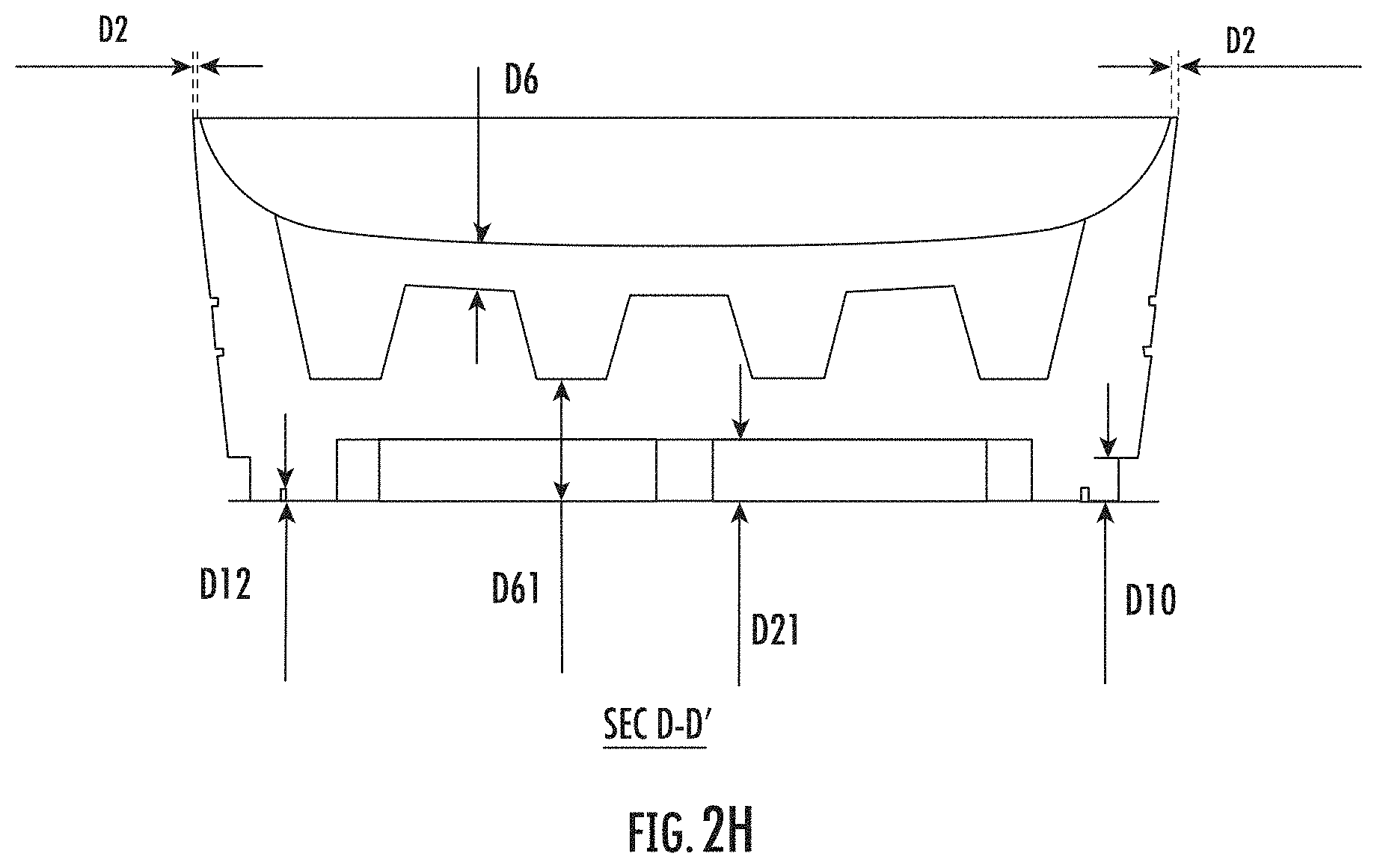
[0024] FIGS. 2A-2H illustrate various example views of an example outsole in accordance with various embodiments of the present disclosure;
[0025] FIG. 3 illustrates an example outsole in accordance with various embodiments of the present disclosure;
[0026] FIG. 4 illustrates an example outsole in accordance with various embodiments of the present disclosure;
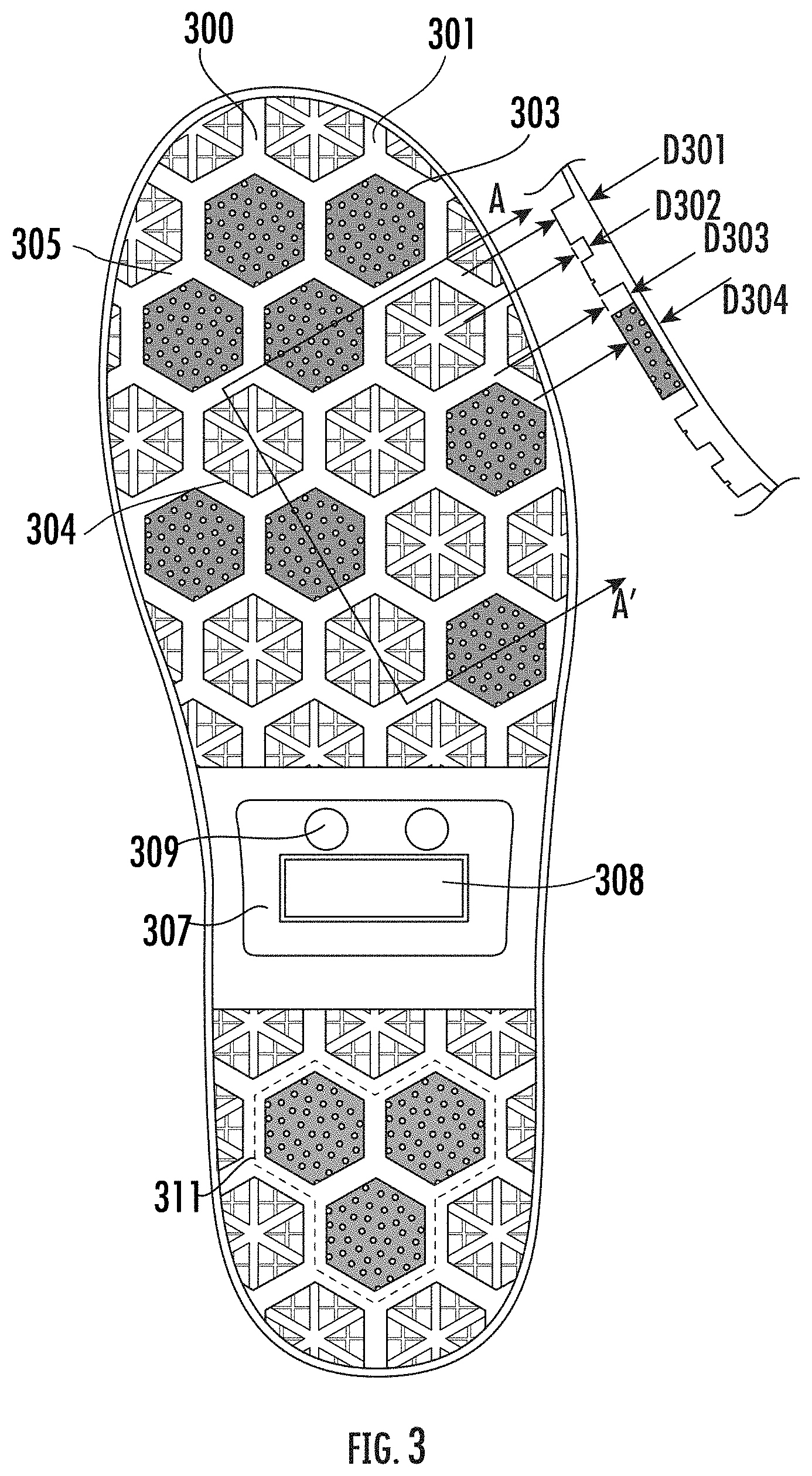
[0027] FIG. 5 illustrates an example outsole in accordance with various embodiments of the present disclosure;
[0028] FIG. 6 illustrates an example outsole in accordance with various embodiments of the present disclosure;
[0029] FIG. 7 illustrates an example outsole in accordance with various embodiments of the present disclosure;
[0030] FIG. 8 illustrates an example outsole in accordance with various embodiments of the present disclosure;
[0031] FIG. 9 illustrates an example outsole in accordance with various embodiments of the present disclosure; and
[0032] FIGS. 10-13 illustrate example views of example outsoles in accordance with various embodiments of the present disclosure.
DETAILED DESCRIPTION OF THE INVENTION
[0033] Some embodiments of the present disclosure will now be described more fully hereinafter with reference to the accompanying drawings, in which some, but not all embodiments of the disclosure are shown. Indeed, these disclosures may be embodied in many different forms and should not be construed as limited to the embodiments set forth herein; rather, these embodiments are provided so that this disclosure will satisfy applicable legal requirements. Like numbers refer to like elements throughout.
[0034] The phrases "in one embodiment," "according to one embodiment," and the like generally mean that the particular feature, structure, or characteristic following the phrase may be included in at least one embodiment of the present disclosure, and may be included in more than one embodiment of the present disclosure (importantly, such phrases do not necessarily refer to the same embodiment).
[0035] The word "example" or "exemplary" is used herein to mean "serving as an example, instance, or illustration." Any implementation described herein as "exemplary" is not necessarily to be construed as preferred or advantageous over other implementations.
[0036] If the specification states a component or feature "may," "can," "could," "should," "would," "preferably," "possibly," "typically," "optionally," "for example," "often," or "might" (or other such language) be included or have a characteristic, that a specific component or feature is not required to be included or to have the characteristic. Such component or feature may be optionally included in some embodiments, or it may be excluded.
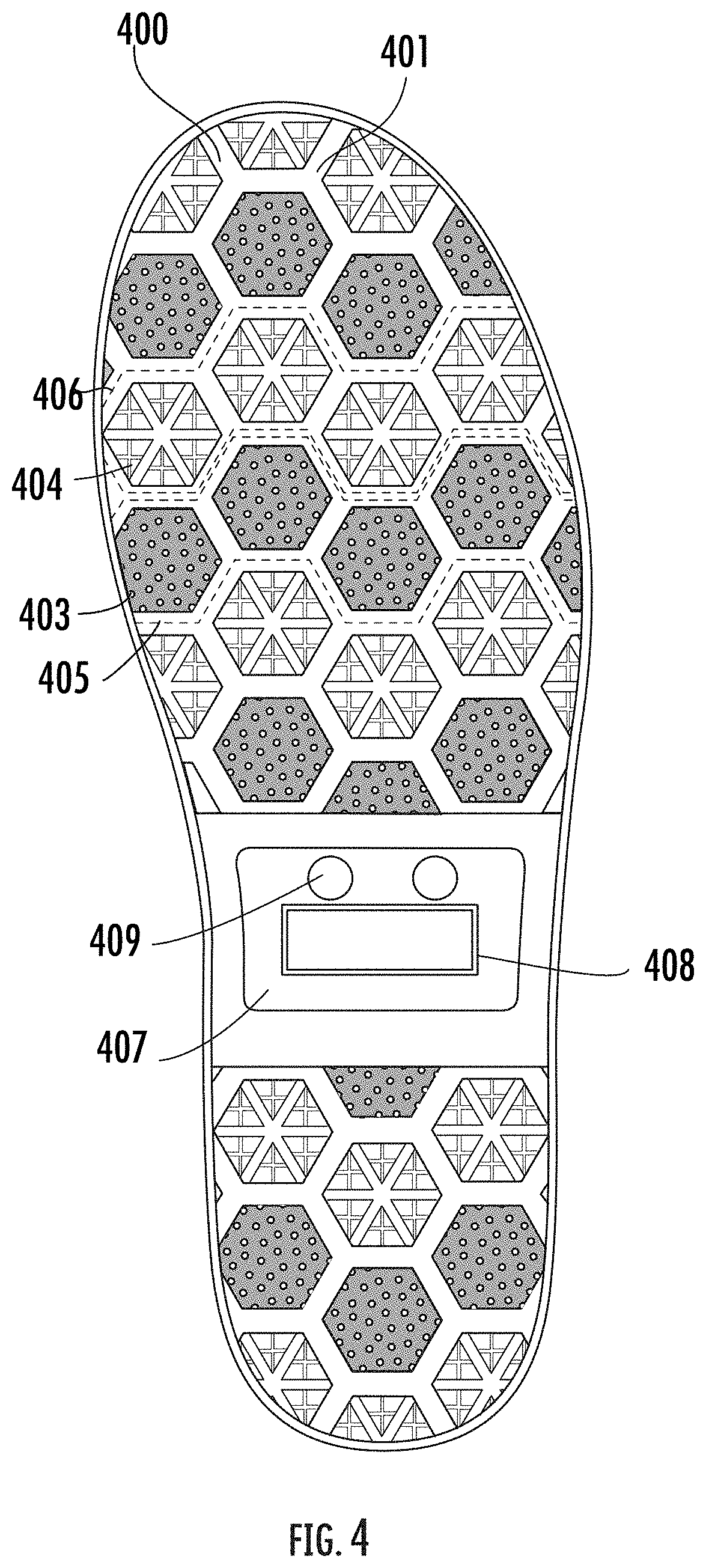
[0037] Referring now to FIG. 1, an example footwear 100 is provided.
[0038] As used herein, the term "footwear" refers generally to an article (such as a garment) that is worn on the foot. Footwear may serve the purpose of protecting the feet against environmental adversities, easing locomotion, and/or preventing injuries. Footwear may be categorized based on types. Example types of footwear include, for example, boots, shoes, sandals, socks, and the like. Footwear may also be categorized based on the desired environment or purpose for wearing the footwear (for example, safety footwear for improving worker safety in heavy duty environments, athletic footwear for improving athlete performance, indoor footwear for indoor use, etc.).
[0039] While FIG. 1 illustrates an example boot (indicated as footwear 100), the scope of the present disclosure is not limited to boots, and embodiments of the present disclosure may be incorporated into other types of footwear without deviating from the scope of the present disclosure.
[0040] As shown in FIG. 1, the footwear 100 may include various components, including, for example, a collar 103, an upper 105, and a sole 107.
[0041] The collar 103 refers to the portion of the footwear 100 that may cover the lower leg of the wearer when the footwear 100 is in use. As shown in FIG. 1, the collar 103 may include various components, including, for example, a liner 111 and a heel loop 113. The liner 111 forms the rims of the collar 103, and may be made of soft or elastic material that facilitates a user in putting on the footwear 100. When a user wants to put on the footwear 100, the user may push his foot through the opening defined by the collar 103 and pull the heel loop 113, so that the heel of the foot can slide smoothly down.
[0042] The upper 105 refers to the portion of the footwear 100 that covers the foot. As shown in FIG. 1, the upper 105 may include various components, including, for example, an upper liner 115, a heel counter 117 and a toe cap 121. The upper liner 115 connects the collar 103 to the upper 105, and may be made of flexible material. The heel counter 117 refers to the rear portion of the footwear 100 that helps maintain the shape of the footwear 100. The heel counter 117 may be made of stiff material. The toe cap 121 refers to the front portion of the footwear that houses toes of the foot wearing the footwear 100. As shown in FIG. 1, the upper 105 is joined to the collar 103, with an upper portion of upper 105 mated to a lower portion of the collar 103. For example, the upper liner 115 may provide structural support for mating the upper 105 and the collar 103. In some examples, an edge of the upper 105 may be stitched, sew, or otherwise mended to an edge of the collar 103, and the upper liner 115 is not used.
[0043] The sole 107 refers to the portion of the footwear that is below the wearer's foot when the footwear is in use. As shown in FIG. 1, the sole 107 may include various components, including, for example, a midsole 108 and an outsole 109. The term "outsole" refers to the layer of sole that is exposed on the bottom of the footwear 100 and configured for contacting the ground when in use. In this regard, example outsoles as described herein may be implemented in different types of footwear, including, but not limited to, shoes, boots, and others. The term "midsole" refers to the structural and cushioning portion of the sole that is configured to support the weight of the wearer when the footwear 100 is in use. As shown in FIG. 1, the midsole 108 is joined to a lower portion of the upper 105 and generally defines a footbed on which a user's foot may rest. The outsole 109 is affixed to (and covers) a bottom portion of the midsole 108, thereby being configured to contact the ground in use.
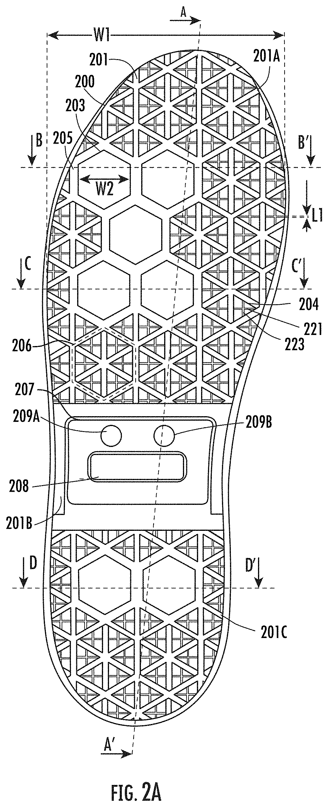
[0044] Referring now to FIGS. 2A-2H, various views of an example footwear outsole in accordance with various embodiments of the present disclosure are illustrated.
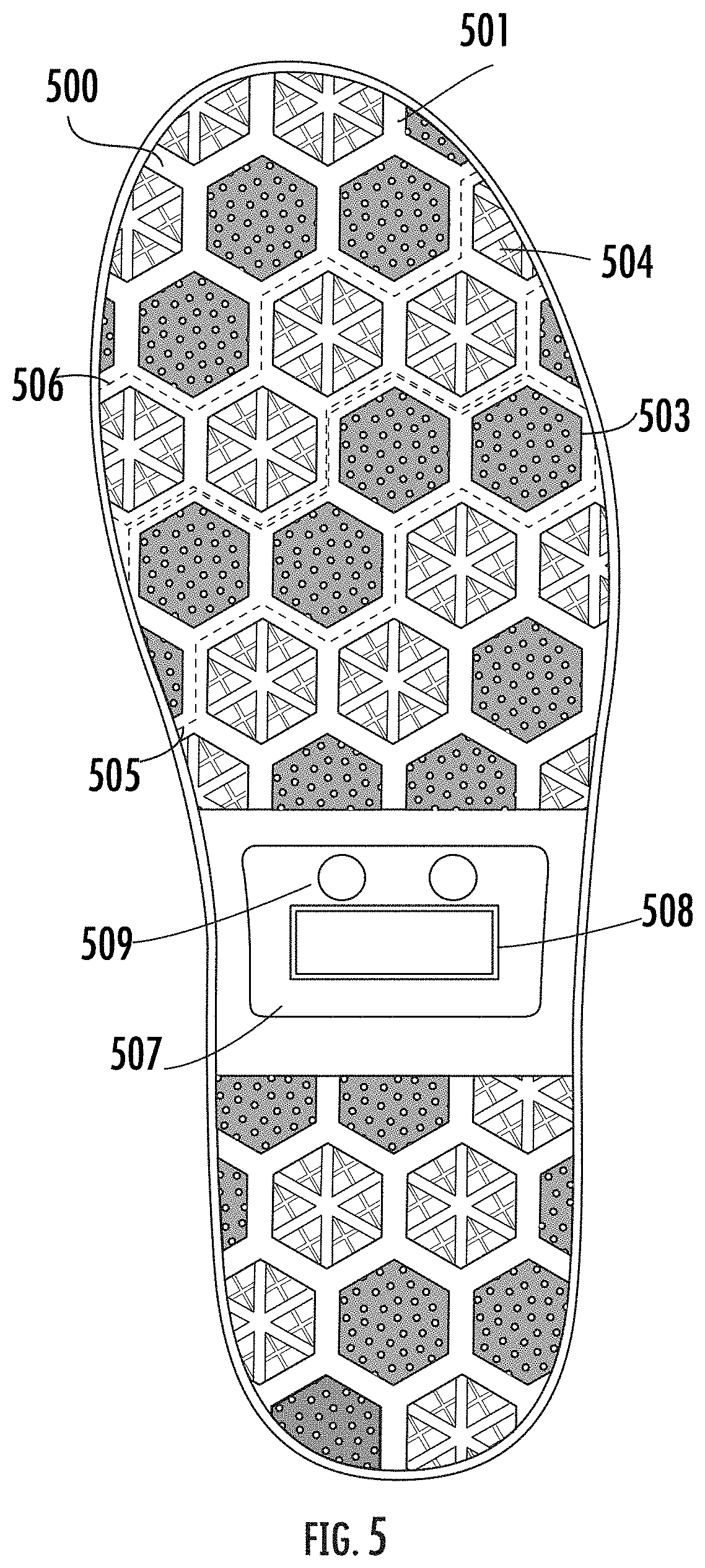
[0045] FIG. 2A illustrates an example bottom view of the example outsole. The example outsole as illustrated in FIG. 2A may include a base 200, which defines the bottom surface of the outsole. The base 200 may have an outer surface 201 (for example, as shown in FIG. 2A), and an inner surface 202 (for example, as shown in FIG. 2D).
[0046] In some examples, the base 200 may be made of rubber material. In some examples, the rubber material may have stiffness properties such that the base 200 may provide structural support as the wearer of the footwear stands. Alternatively, or additionally, the rubber material may have resilience properties such that the base 200 may flex and/or bend as the wearer of the footwear walks. Alternatively, or additionally, the base 200 may be made of or contain material other than rubber.
[0047] In some examples, to manufacture the base 200, a liquid form of the material may be shaped using a rigid frame ("a mold"). The mold resembles the shapes of the base. Alternatively, or additionally, the base 200 may be manufactured through other process, including, for example, through a 3D printing process.
[0048] The example outsole as illustrated in FIG. 2A may include a plurality of resistance elements disposed on the base 200, including, for example, the plurality of first resistance elements 203 and the plurality of second resistance elements 204.
[0049] As used herein, the term "resistance element" refers to a structure that is disposed on and protrudes from the base 200 of the outsole as shown in FIG. 2A. As described in greater detail herein, the resistance elements are generally configured to provide resistance against slippage when the outsole is in contact with a ground surface. In some examples, a resistance element may be made of rubber material, including, for example, nitrile rubber (NBR). Alternatively, or additionally, a resistance element may be made of or contain material other than rubber. In some examples, the resistance elements may be molded, affixed and/or attached onto the base 200. Alternatively, or additionally, the resistance elements may be formed by etching into an outer surface 201 of the base 200, leaving resistance elements protruding from the base 200.
[0050] As described herein, one or more resistance elements may be arranged, neighbor, be joined, or otherwise be linked to form a configuration of resistance elements that, in some examples, may provide one or more benefits to slip resistance in complex surfaces (including, for example, oily, icy, and/or wet surfaces or a combination of oily, icy, and/or wet surfaces).
[0051] In various embodiments of the present disclosure, the plurality of resistance elements may comprise a plurality of first resistance elements 203 and a plurality of second resistance elements 204. Further, the plurality of resistance elements may be arranged in different types of configurations. In this regard, part of the plurality of first resistance elements 203 may be arranged in a first type configuration 205, and part of the plurality of second resistance elements 204 may be arranged in a second type configuration 206.
[0052] In the illustrated embodiment of FIG. 2A, each of the plurality of first resistance elements 203 defines a hexagonal shape. Further, the plurality of first resistance elements 203 may be arranged in various configurations. For example, five of the plurality of first resistance elements may be arranged in a first type configuration 205. In the illustrated embodiment of FIG. 2A, for example, a first type configuration 205 is X-shaped (e.g., where the plurality of first resistance elements 203 are arranged in a shape generally resembling the capitalized letter X in the English alphabet). In some examples, the first type configuration 205 may be formed by less than five or more than five first resistance elements, without deviating from the scope of the present disclosure.
[0053] In the illustrated embodiment of FIG. 2A, each of the second resistance elements 204 defines a triangular shape. In some examples, at least some of the second resistance elements 204 define isosceles triangles. In some examples, each of the second resistance elements 204 is of the same size. In other embodiments, the plurality of second resistance elements may have different sizes.
[0054] In some examples, at least some of the resistance elements may have one or more gap segments. The term "gap segment" refers to the portion of a resistance element where there is a break of protrusion from the base. A gap segment may be formed through, for example, a molding process with a mold defining the gap segments. Additionally, or alternative, a gap segment may be formed by etching into a resistance element.
[0055] For example, in the illustrated embodiment of in FIG. 2A, each of the plurality of second resistance elements 204 includes a longitudinal gap segment 223 and a transverse gap segment 221. The longitudinal gap segment 223 may be aligned with a longitudinal direction of the outer surface 201 of the base 200, and the transverse gap segment 221 may be aligned with a transverse direction of the outer surface 201 of the base 200. As described herein, the term "longitudinal direction" refers to a direction aligned with the length of the footwear, and the term "transverse direction" refers to a direction aligned with the width of the footwear.
[0056] In some examples, at least part of the plurality of second resistance elements 204 may be arranged in a second type configuration. For example, in the illustrated embodiment of in FIG. 2A, six second resistance elements 204 are arranged in a second type configuration 206 in the form of a hexagonal shape (e.g., six resistance elements 204 are arranged such that--together--they resemble a hexagon). In some examples, the second type configuration 206 may be formed by less than six or more than six second resistance elements, without deviating from the scope of the present disclosure.
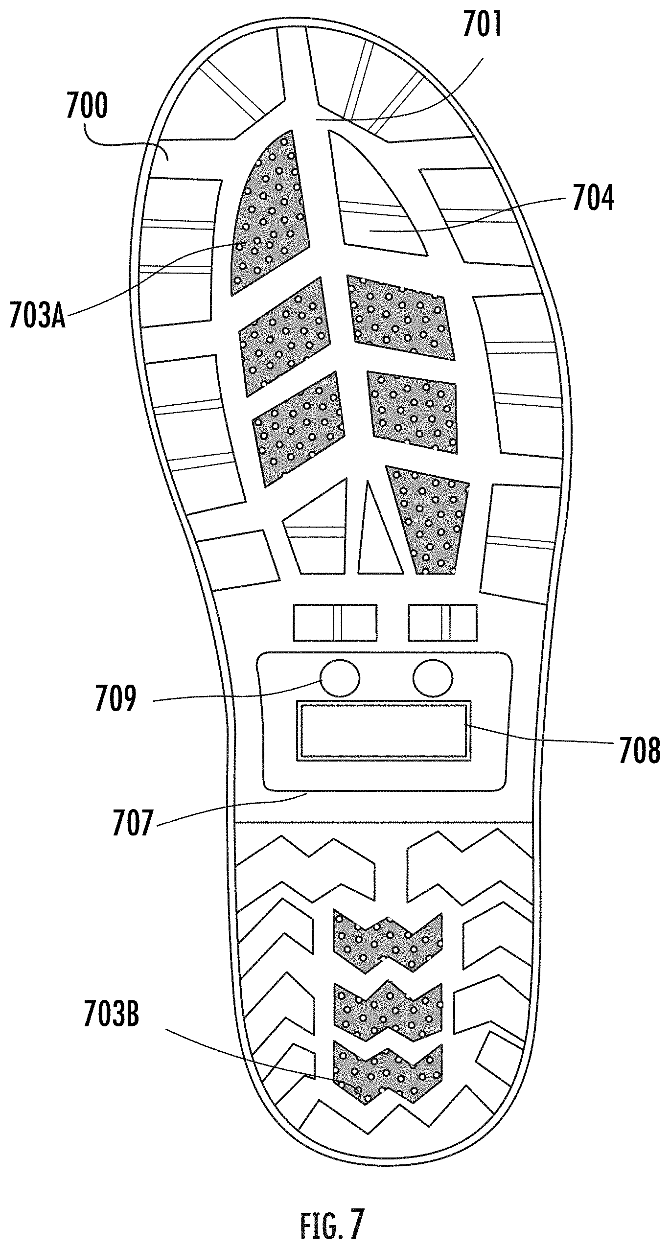
[0057] In the illustrated embodiment of FIG. 2A, the outer surface 201 of the base 200 may comprise a top portion 201A, a middle portion 201B, and a bottom portion 201C. A plurality of first resistance elements 203 and plurality of second resistance elements 204 are disposed on the top portion 201A and the bottom portion 201C. However, in the illustrated embodiment of in FIG. 2A, the plurality of first resistance elements 203 and the plurality of second resistance elements 204 are not disposed on the middle portion 201B.
[0058] The middle portion 201B may optionally include one or more labels 207, such as brand label 208 and size labels 209A and 209B. The brand label 208 may indicate the branding information of the footwear, and the size labels 209A and 209B may indicate the size information of the footwear. In some examples, there is no brand label 208 or size labels 209A and 209B on the middle portion 201B of the outer surface 201.
[0059] As described above, embodiments of the present disclosure provide improved slip resistance performance for footwear. In this regard, the plurality of first resistance elements 203 may be made of a different material than that of plurality of second resistance elements 204, so that they have different slip resistance performance, such as, for example, different coefficient of friction on different surfaces.
[0060] As used herein, the term "coefficient of friction" or COF is a value that indicates the relationship between two surfaces (such as, for example, the outer surface of the outsole and the surface that the outsole is on), and the force applied between the two surfaces vertically and laterally. In some examples, a higher coefficient of friction means that there is more friction and more traction (i.e. more slip resistance). A lower coefficient of friction means that there is less traction (i.e. more slippery).
[0061] A variety of factors may affect the coefficient of friction of an outsole, including, for example, the material that the outsole is made of, configuration(s) disposed on the outsole surface, and the condition of the contact surface that the outsole is on (e.g. whether the surface is icy, wet, and/or oily). In other words, the same outsole may have a different coefficient of friction on an icy surface (i.e. a surface that at least partially includes ice) than on a wet surface (i.e. a surface that at least partially includes water).
[0062] For example, an icy surface coefficient of friction may indicate the coefficient of friction of an example outsole on an icy surface (i.e. a surface that at least partially includes ice). In this regard, at least a first part of the plurality of first resistance elements 203 are arranged in the first type configuration 205, and the first part of the plurality of first resistance elements 203 have a first coefficient of friction with respect to an icy surface. A first part of the plurality of second resistance elements 204 are arranged in a second type configuration 206, and the first part of the plurality of second resistance elements 204 have a second coefficient of friction with respect to the icy surface. The first coefficient of friction may be higher than the second coefficient of friction. In other words, the first type configuration 205 may provide better slip resistant performance on an icy surface than that of the second type configuration 206.
[0063] Additionally, or alternatively, a wet surface coefficient of friction may indicate the coefficient of friction of an example outsole on a wet surface (i.e. a surface that at least partially includes water). In this regard, the first part of the first plurality of resistance elements 203 has a third coefficient of friction associated with a wet surface, and the first part of the second plurality of resistance elements 204 has a fourth coefficient of friction associated with the wet surface. The fourth coefficient of friction may be higher than the third coefficient of friction. In other words, the second type configuration 206 may provide better slip resistant performance on a wet surface than the first type configuration 205.
[0064] In some examples, by combining different types of resistance elements (e.g. the plurality of first resistance elements 203 and the plurality of second resistance elements 204) and their corresponding configurations, example outsoles in accordance with the present disclosure may improve slip resistance performance on complex surfaces, including for example, a wet icy surface. In this regard, a wet icy surface coefficient of friction may indicate the coefficient of friction of an example outsole on a wet icy surface (i.e. a surface that at least partially includes water and ice). The first part of the first plurality of resistance elements 203 may have a fifth coefficient of friction associated with a wet icy surface, and the first part of the second plurality of resistance elements 204 may have a sixth coefficient of friction associated with the wet icy surface. The fifth coefficient of friction may be higher than the sixth coefficient of friction.
[0065] Example coefficient of frictions of example outsoles in accordance with the present disclosure are described further in connection with TABLE 1 herein.
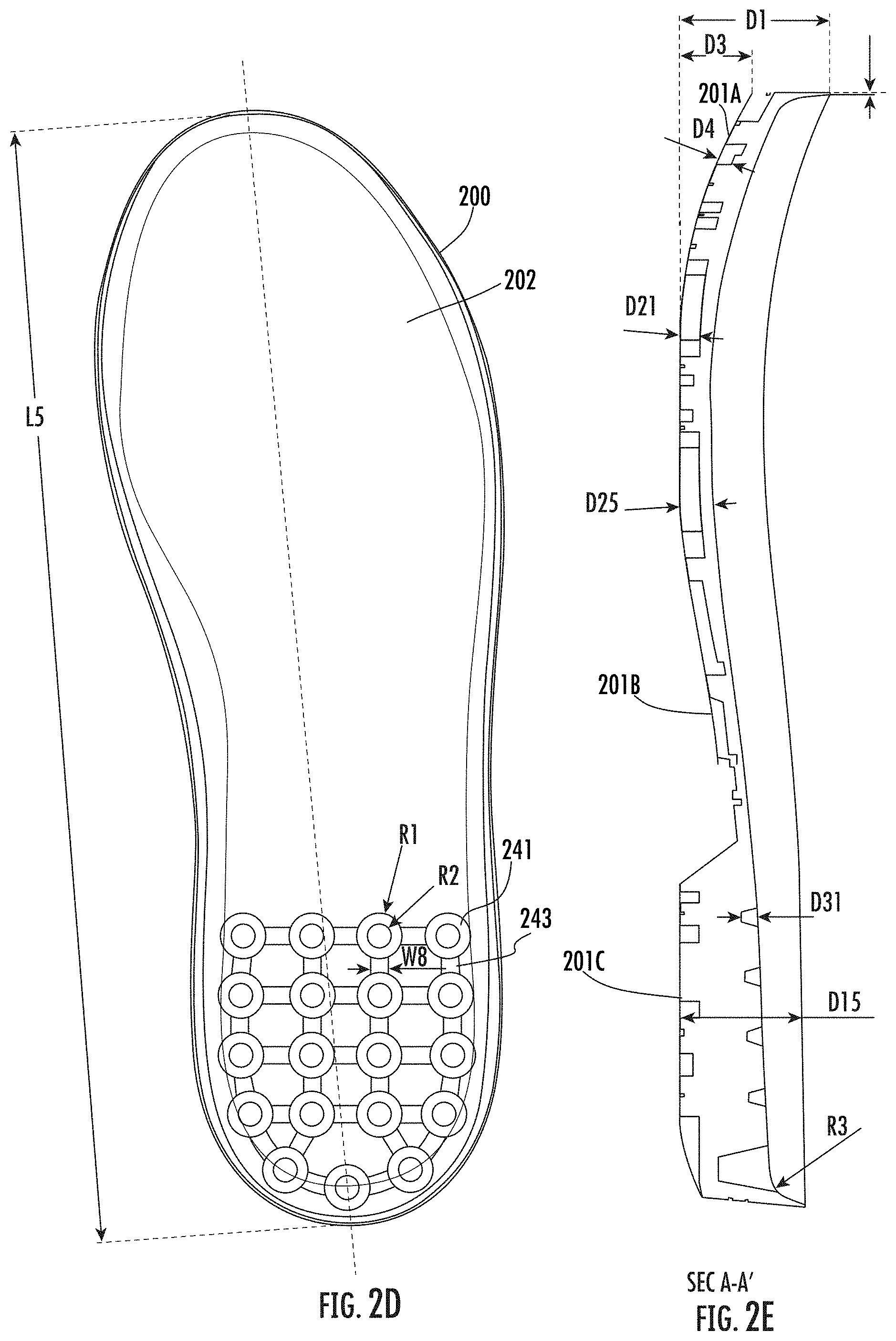
[0066] Referring now to FIG. 2D, an example top view of the base 200 showing the inner surface 202 is illustrated. In some examples, the inner surface 202 may comprise one or more hollow portions, such as ring hollow portions 241 and rectangular hollow portions 243, which are cutout portions of the outsole from the inner surface. The ring hollow portions 241 are cutout portions each in the shape of a ring, and the rectangular hollow portions 243 are cutout portions each in the shape of a rectangle. In some examples, one or more of the ring hollow portions 241 and one or more of the rectangular hollow portions 243 may be linked.
[0067] The inner surface 202 of the base 200 is secured to the footwear (e.g., to the midsole 108). As such, the ring hollow portions 241 and rectangular hollow portions 243 are near the heel of the footwear. In some examples, the ring hollow portions 241 and the rectangular hollow portions 243 may reduce the weight of the heel and make the footwear light to wear.
[0068] While in the embodiment as illustrated in FIG. 2D, the one or more hollow portions of the inner surface 202 are in the shapes of rings or rectangles, it is noted that the hollow portions may additionally or alternatively resemble other shapes (including, for example, triangles, circles, hexagons) without deviating from the scope of the present disclosure. In some examples, the inner surface 202 does not include any hollow portion.
[0069] In FIGS. 2A-2H, various example measurements of the footwear, including the base 200 and the plurality of resistance elements (such as the plurality of first resistance elements 203 and the plurality of second resistance elements 204), are illustrated. It is noted that these measurements are for example purpose only, and the present disclosure is not limited to these particular measurements.
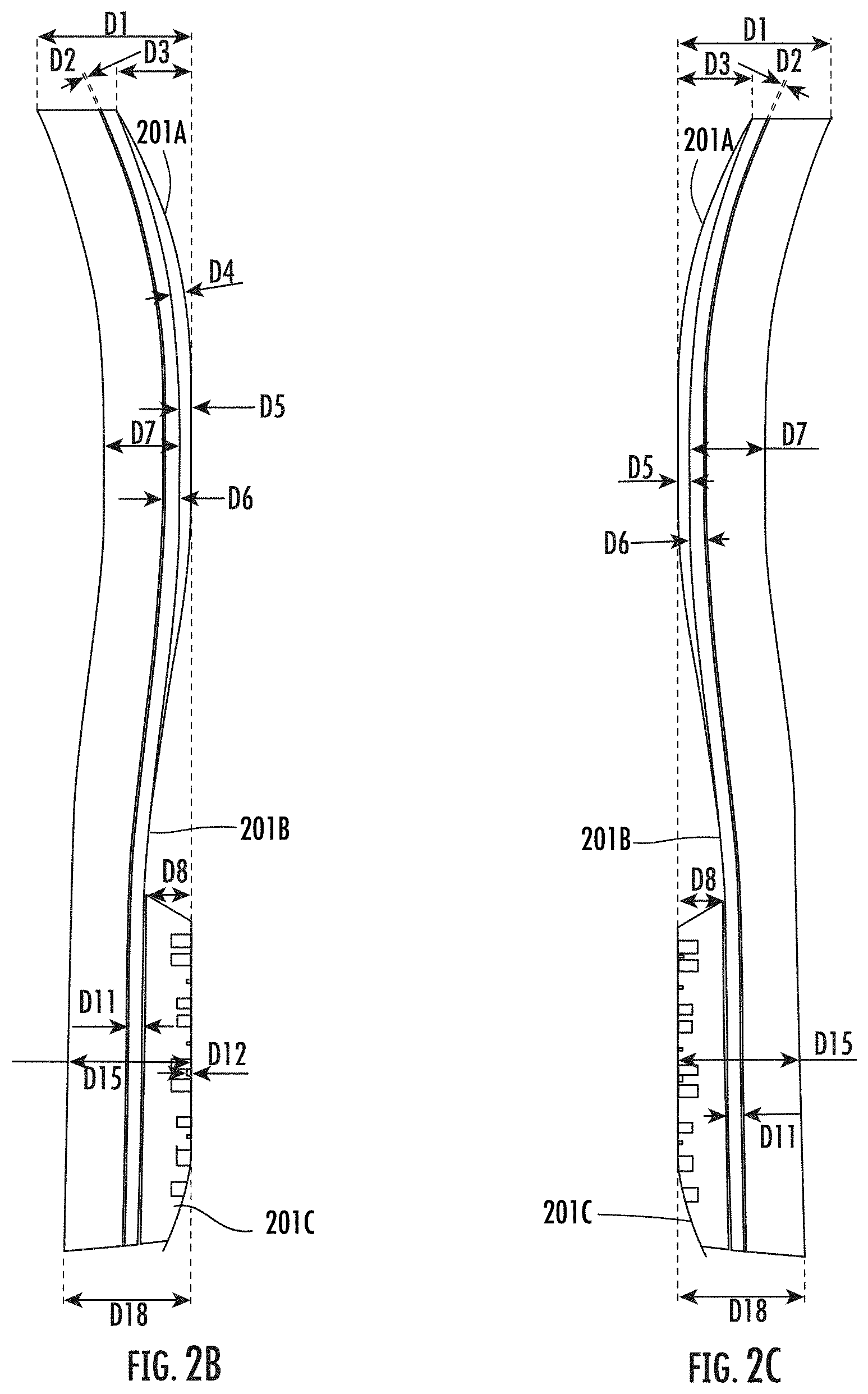
[0070] Referring now to FIGS. 2B-2E, FIG. 2B illustrates an example outside side view of the example sole including the base 200; FIG. 2C illustrates an example inside side view of the example sole including the base 200; FIG. 2D illustrates an example top view of the example sole including the base 200; and FIG. 2E illustrates a cross-sectional view based on line A-A' as shown in FIG. 2A of the example sole including the base 200.
[0071] Referring now to FIG. 2B, the top portion 201A may have an example greatest thickness D1 in the example range of 35.00 mm to 43.00 mm, preferably 39.00 mm. The sole may have different layers, including a first layer, a second layer, a third layer, and a fourth layer.
[0072] In some examples, the first, second, and third layers may have a total thickness of D7 in the example range of 17.00 mm to 21.00 mm, preferably 19.00 mm. In some examples, the second layer depth D2 may be in the example range of 0.3 mm to 0.7 mm, preferably 0.5 mm.
[0073] In some examples, the third layer may have varying thickness. For example, the third layer may have a first example thickness D6 in the example range of 3.3 mm to 3.7 mm, preferably 3.5 mm, and a second example thickness D11 in the example range of 3.3 mm to 3.7 mm, preferably 3.5 mm.
[0074] The fourth layer may have varying thickness, and may be curved in the top portion 201A. As illustrated in FIG. 2B, the fourth layer may have a depth D3 from the top of the fourth layer to the ground, and D3 may be in the example range of 17.00 mm to 21.00 mm, preferably 19.00 mm. The fourth layer may have a first thickness D4 and a second thickness D5. In some examples, D4 may be in the example range of 3.3 mm to 3.7 mm, preferably 3.5 mm. In some examples, D5 may be in the example range of 2.8 mm to 3.2 mm, preferably 3.0 mm. In some examples, D4 and D5 may have the same value. In some examples, D4 and D5 may have difference values.
[0075] The bottom portion 201C may have varying thickness. For example, the bottom portion 201C may have a first thickness D15 in the example range of 30.00 mm to 33.00 mm, preferably 31.50 mm, and a second thickness D18 in the example range of 30.00 mm to 35.00 mm, preferably 32.50 mm. The fourth layer on the bottom portion 201C (i.e. the heel of the footwear) may have an example depth D8 in the example range of 10.00 mm to 14.00 mm, preferably 12.00 mm.
[0076] As described above, the second resistance elements 204 may include a transverse gap segment 204A. As shown in FIG. 2A, the transverse gap segment 204A may have an example width L1 in the example range of 0.3 mm to 0.7 mm, preferably 0.5 mm. As shown in FIG. 2B, the transverse gap segment 204A may have an example depth D12 in the example range of 0.5 mm to 1.5 mm, preferably 1.0 mm. Further, as shown in the embodiment illustrated in FIG. 2B, an example gap segment between two neighboring second resistance elements 204 may have an example depth D10 in the example range of 3.2 mm to 3.7 mm, preferably 3.5 mm.
[0077] Referring now to FIG. 2D, the example outsole may have an example greatest length L5 in the example range of 250.0 mm to 330.00 mm, preferably 290.00 mm. In some examples, L5 may be in other values without deviating from the scope of the present disclosure.
[0078] In the illustrated embodiment of in FIG. 2D, as described above, the inner surface 202 may comprise ring hollow portions 241 and rectangular hollow portions 243. In some examples, the ring hollow portions 241 may have a first radius R1 in the example range of 10.00 mm to 14.00 mm, preferably 12.00 mm, and a second radius R2 in the example range of 4.0 mm to 8.0 mm, preferably 6.00 mm. In some examples, the rectangular hollow portions 243 may have an example width in the example range of 4.0 mm to 5.0 mm, preferably 4.5 mm.
[0079] As shown in FIG. 2E, the ring hollow portions 241 may have an example depth D31 in the example range of 2.5 mm to 5.5 mm, preferably 4.0 mm. Further, the hollow portions may have an example radius R3 in the example range of 5.00 mm to 9.00 mm, preferably 7.00 mm. As shown in FIG. 2H, the rectangular hollow portions 243 may have an example depth D6 in the example range of 3.00 mm to 5.00 mm, preferably 4.00 mm. Further, the distance D61 is the distance between the bottom surface of the ring hollow portions 241 and the outer surface 201 of the base 200, and D61 may be in the example range of 8.00 mm to 12.00 mm, preferably 10.00 mm.
[0080] Further, as shown in FIG. 2E, a first resistance element 203 may have an example thickness D21 in an example range of 3.0 mm to 7.0 mm, preferably 5.0 mm. An example combined depth D25 of the first resistance element and the base may be in an example range of 5.00 mm to 11.00 mm, preferably 8.0 mm. As shown in FIG. 2A, a first resistance element 203 may have an example diameter W2 in the example range of 21.3 mm to 23.3 mm, preferably 22.3 mm.
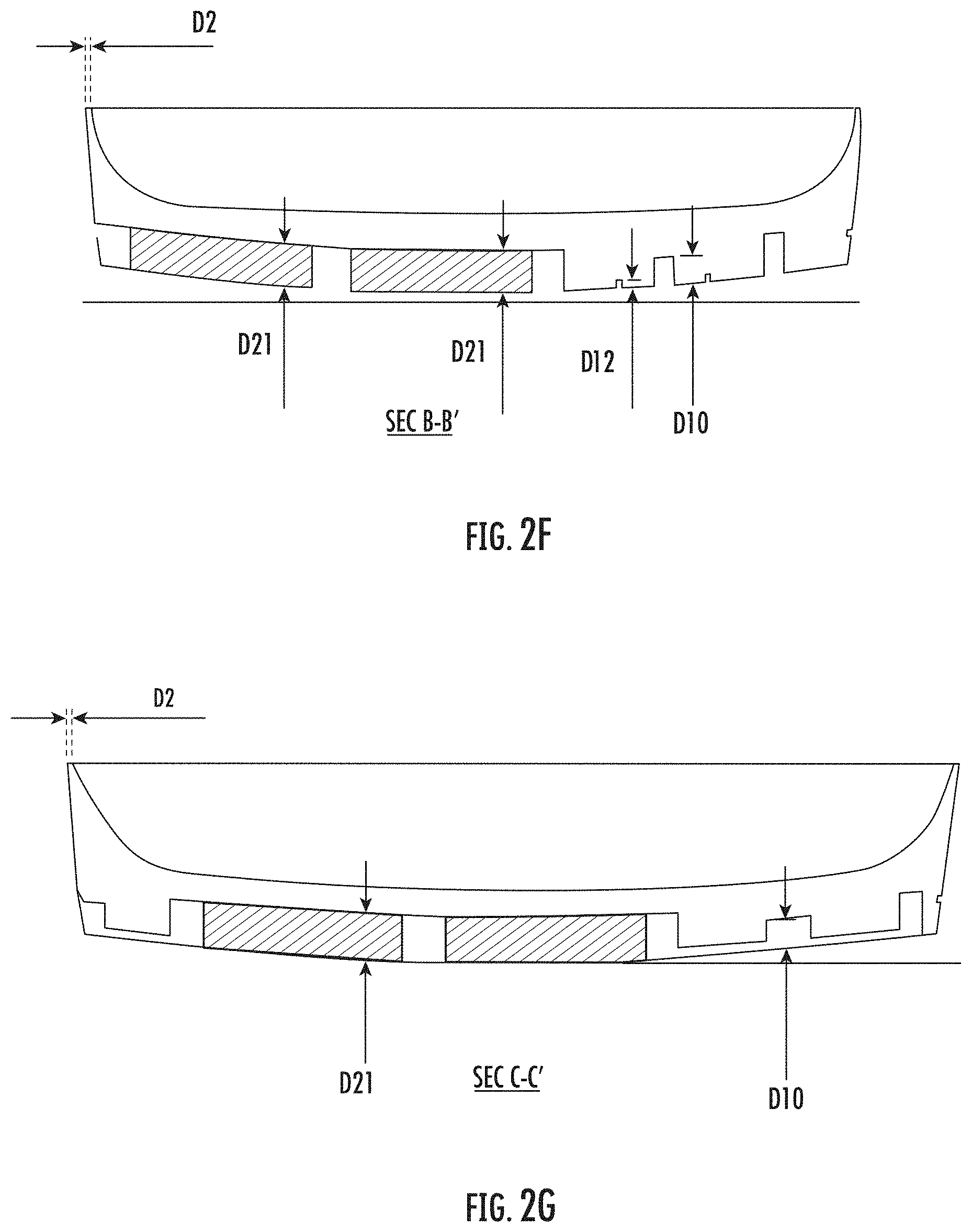
[0081] Referring now to FIGS. 2F-2H, FIG. 2F illustrates a cross-sectional view based on line B-B' as shown in FIG. 2A, FIG. 2G illustrates a cross-sectional view based on line C-C' as shown in FIG. 2A, and FIG. 2H illustrates a cross-sectional view based on line D-D' as shown in FIG. 2A. In particular, FIGS. 2F, 2G, and 2H further illustrate example measurements described above.
[0082] Referring now to FIG. 3, an example footwear outsole according to another embodiment is illustrated. In the illustrated embodiment of FIG. 3, the example outsole includes a base 300, which has an outer surface 301 (e.g., similar to the outer surface 201 as described above in connection with FIG. 2A).
[0083] The example outsole as illustrated in FIG. 3 may include a plurality of resistance elements disposed on the outer surface 301 of the base 300, including, for example, a plurality of first resistance elements 303 and a plurality of second resistance elements 304. In this regard, the plurality of first resistance elements 303 may be made of a material similar to that of the plurality of first resistance elements 203 as described above in connection with FIGS. 2A-2H, and the plurality of second resistance elements 304 may be made of a material similar to that of the plurality of second resistance elements 204 as described above in connection with FIGS. 2A-2H.
[0084] Similar to the plurality of second resistance elements 204 as described above in connection with FIGS. 2A-2H, the plurality of second resistance elements 304 may form a second type configuration in a hexagonal shape.
[0085] Further, as illustrated in FIG. 3, the plurality of first resistance elements 303 may be arranged in different types of configurations. For example, four of the plurality of the first resistance elements may be arranged in a configuration 305 that defines a parallelogrammatic or quadrilateral shape (i.e. connecting the centers of these first resistance elements would create a parallelogram or quadrilateral shape). As another example, three of the plurality of the first resistance elements may be arranged in a configuration 311 that defines a triangular shape (i.e. connecting the centers of these first resistance elements would create a triangle shape).
[0086] In some examples, the configuration 305 may be formed by less than four or more than four first resistance elements, and/or the configuration 311 may be formed by less than three or more than three first resistance elements. In some examples, one or more configurations may be of other shapes.
[0087] In some examples, different configurations may provide different coefficients of friction on icy surface and/or wet surface.
[0088] Additionally, or alternatively, one or more labels 307 may be disposed on the outer surface 301, such as, for example, brand label 308 and size labels 309. The brand label 308 may indicate the branding information of the footwear, and the size labels 309 may indicate the size information of the footwear. In some examples, there is no label on the outer surface 301.
[0089] In the illustrated embodiment of FIG. 3, various example measures of the base 300 and the plurality of resistance elements (including the plurality of first resistance elements 303 and the plurality of second resistance elements 304) are illustrated. It is noted that these measurements are for examples only, and the present disclosure is not limited to these particular measurements.
[0090] For example, FIG. 3 illustrate a cross-sectional view A-A' of the base 300. As shown, the base 300 may have a thickness D301, which may be in the example range of 6.0 mm to 10.0 mm, preferably 8.00 mm. As described above, the second resistance elements 304 may form a hexagonal shape, which may comprise a gap segment having a depth of D302 from the surface. In some examples, D302 may be in the example range of 3.0 mm to 6.0 mm, preferably 5.0 mm.
[0091] Further, in some examples, the gap segment between a first resistance element 303 and a second resistance element 304 may have a depth of D303, which may be in the example range of 5.0 mm to 7.0 mm, preferably 6.0 mm.
[0092] Further, in some examples, the outer surface of the first resistance elements 303 to the inner surface of the base 300 may have a depth of D304. In some examples, D304 has the same value as D301. In such examples, the height of the first resistance element has the same value as D303. In some examples, D304 and D301 may have different values.
[0093] Referring now to FIG. 4, an example footwear outsole according to another embodiment is illustrated.
[0094] The example outsole as illustrated in FIG. 4 may include a plurality of resistance elements disposed on the outer surface 401 of the base 400, including, for example, a plurality of first resistance elements 403 and a plurality of second resistance elements 404. In this regard, the plurality of first resistance elements 403 may be made of a material similar to that of the plurality of first resistance elements 203 as described above in connection with FIGS. 2A-2H, and the plurality of second resistance elements 404 may be made of a material similar to that of the plurality of second resistance elements 204 as described above in connection with FIGS. 2A-2H. Further, as illustrated in FIG. 4, the plurality of first resistance elements 403 and the plurality of second resistance elements 404 may be arranged in different types of configurations than those described in connection with FIGS. 2A-2H.
[0095] In particular, the first resistance elements 403 may be arranged in a hexagonal band configuration 405. The hexagonal band configuration 405 includes a plurality of neighboring first resistance elements 403. In the hexagonal band configuration 405, each of the first resistance elements 403 is in the shape of a hexagon, and connecting centers of these hexagons would create a waveform that resembles a triangle wave. In some examples, the first resistance elements 403 may be arranged such that the waveform may resemble other waves, such as, for example, a square wave or a sawtooth wave.
[0096] As shown in FIG. 4, the hexagonal band configuration 405 may be aligned with the transverse direction of the outer surface 401 of the base 400. In some examples, the hexagonal band configuration 405 may be aligned with a different direction, such as in the longitudinal direction of the outer surface 401.
[0097] Similarly, the plurality of second resistance elements 404 may be arranged in a hexagonal band configuration 406. In particular, the plurality of second resistance elements 404 may be arranged in configurations in the shapes of neighboring hexagons, and connecting centers of these hexagons would create a waveform that resembles a triangle wave. As shown in FIG. 4, the hexagonal band configuration 406 may be aligned with the transverse direction of the outer surface 401 of the base 400. In some examples, the hexagonal band configuration 406 may be aligned with a different direction, such as in the longitudinal direction of the outer surface 401.
[0098] Further, in the embodiment as illustrated in FIG. 4, each one of the hexagonal band configurations formed by the first resistance elements 403 may be between two hexagonal band configurations formed by the second resistance elements 404, and each one of the hexagonal band configurations formed by the second resistance elements 404 may be between two hexagonal band configurations formed by the first resistance elements 403. In some examples, a hexagonal band configuration formed by the first resistance elements 403 may be between less than two or more than two hexagonal band configurations formed by the second resistance elements 404. In some examples, a hexagonal band configuration formed by the second resistance elements 404 may be between less than two or more than two hexagonal band configurations formed by the first resistance elements 403.
[0099] In some examples, different configurations may provide different coefficients of friction on icy surface and/or wet surface.
[0100] Additionally, or alternatively, one or more labels 407 may be disposed on the outer surface 401, such as, for example, brand label 408 and size labels 409. The brand label 408 may indicate the branding information of the footwear, and the size labels 409 may indicate the size information of the footwear. In some examples, there is no label on the outer surface 401.
[0101] Referring now to FIG. 5, an example footwear outsole according to another embodiment is illustrated.
[0102] The example outsole as illustrated in FIG. 5 may include a plurality of resistance elements disposed on the outer surface 501 of the base 500, including, for example, a plurality of first resistance elements 503 and a plurality of second resistance elements 504. In this regard, the plurality of first resistance elements 503 may be made of a material similar to that of the plurality of first resistance elements 203 as described above in connection with FIGS. 2A-2H, and the plurality of second resistance elements 504 may be made of a material similar to that of the plurality of second resistance elements 204 as described above in connection with FIGS. 2A-2H.
[0103] Further, as illustrated in FIG. 5, the plurality of first resistance elements 503 may be arranged in a hexagonal band configuration 505 similar to the hexagonal band configuration 405 described above in connection with FIG. 4, and the plurality of second resistance elements 504 may be arranged in a hexagonal band configuration 506 similar to the hexagonal band configuration 406 described above in connection with FIG. 4.
[0104] As shown in FIG. 5, the hexagonal band configuration 505 and the hexagonal band configuration 506 may be at an angle from a transverse direction of the outer surface 501 of the base 500. In some examples, the hexagonal band configuration 505 and the hexagonal band configuration 506 may be at a different direction. In some examples, the hexagonal band configuration 505 and the hexagonal band configuration 506 may intersect, and they may be arranged so that they together form a shape similar to the capitalized letter X in the English alphabet.
[0105] In some examples, different configurations may provide different coefficients of friction on icy surface and/or wet surface.
[0106] Additionally, or alternatively, one or more labels 507 may be disposed on the outer surface 501, such as, for example, brand label 508 and size labels 509. The brand label 508 may indicate the branding information of the footwear, and the size labels 509 may indicate the size information of the footwear. In some examples, there is no label on the outer surface 501.
[0107] Referring now to FIG. 6, an example footwear outsole according to another embodiment is illustrated.
[0108] The example outsole as illustrated in FIG. 6 may include a plurality of resistance elements disposed on the outer surface 601 of the base 600, including, for example, a plurality of first resistance elements 603 and a plurality of second resistance elements 604. In this regard, the plurality of first resistance elements 603 may be made of a material similar to that of the plurality of first resistance elements 203 as described above in connection with FIGS. 2A-2H, and the plurality of second resistance elements 604 may be made of a material similar to that of the plurality of second resistance elements 204 as described above in connection with FIGS. 2A-2H.
[0109] Further, as shown in FIG. 6, each of the plurality of first resistance elements 603 is in a rhombic shape. The first resistance elements 603 may form a rhombus band configuration 605. The rhombus band configuration 605 includes a plurality of neighboring first resistance elements 603. Each of the first resistance elements 603 is in the shape of a rhombus, and connecting the center of these rhombuses would form a straight line. As shown in FIG. 6, the rhombus band configuration 605 may be aligned with the longitudinal direction of the outer surface 601 of the base 600. In some examples, the rhombus band configuration 605 may be aligned with a different direction, such as in the transverse direction of the outer surface 601.
[0110] Similarly, the plurality of second resistance elements 604 may be arranged in a rhombus band configuration 606. In particular, the plurality of second resistance elements 604 may be arranged in configurations in the shapes of neighboring rhombuses, and connecting the center of these rhombuses would form a straight line. As shown in FIG. 6, the rhombus band configuration 606 may be aligned with the longitudinal direction of the outer surface 601 of the base 600. In some examples, the rhombus band configuration 606 may be aligned with a different direction, such as the transverse direction of the outer surface 601.
[0111] In some examples, different configurations may provide different coefficients of friction on icy surface and/or wet surface.
[0112] Additionally, or alternatively, one or more labels 607 may be disposed on the outer surface 601, such as, for example, brand label 608 and size labels 609. The brand label 608 may indicate the branding information of the footwear, and the size labels 609 may indicate the size information of the footwear. In some examples, there is no label on the outer surface 601.
[0113] Referring now to FIG. 7, an example footwear outsole according to another embodiment is illustrated.
[0114] The example outsole as illustrated in FIG. 7 may include a plurality of resistance elements disposed on the outer surface 701 of the base 700, including, for example, a plurality of first resistance elements 703A and 703B, as well as a plurality of second resistance elements 704. In this regard, the plurality of first resistance elements 703A and 703B may be made of a material similar to that of the plurality of first resistance elements 203 as described above in connection with FIGS. 2A-2H, and the plurality of second resistance elements 704 may be made of a material similar to that of the plurality of second resistance elements 204 as described above in connection with FIGS. 2A-2H.
[0115] Further, as show in FIG. 7, the plurality of first resistance elements 703A and 703B may have different shapes and sizes. For example, one or more of the plurality of first resistance elements may be in a quadrilateral shape, such as the first resistance elements 703A. Another example, one or more of first resistance elements may be in a wave form, such as the first resistance elements 703B. In other examples, the first resistance element may be in other shapes, including, for example, circle, ring, and triangle. Additionally, or alternatively, one or more of the plurality of second resistance elements 704 may be in different shapes.
[0116] In some examples, different configurations may provide different coefficients of friction on icy surface and/or wet surface.
[0117] Additionally, or alternatively, one or more labels 707 may be disposed on the outer surface 701, such as, for example, brand label 708 and size labels 709. The brand label 708 may indicate the branding information of the footwear, and the size labels 709 may indicate the size information of the footwear. In some examples, there is no label on the outer surface 701.
[0118] Referring now to FIG. 8, an example footwear outsole according to another embodiment is illustrated.
[0119] The example outsole as illustrated in FIG. 8 may include a plurality of resistance elements disposed on the outer surface 801 of the base 800, including, for example, a plurality of first resistance elements 803A, 803B, and a plurality of second resistance elements 804. In this regard, the plurality of first resistance elements 803A and 803B may be made of a material similar to that of the plurality of first resistance elements 203 as described above in connection with FIGS. 2A-2H, and the plurality of second resistance elements 804 may be made of a material similar to that of the plurality of second resistance elements 204 as described above in connection with FIGS. 2A-2H. In some examples, different configurations of the plurality of first resistance elements 803A, 803B and the plurality of second resistance elements 804 may provide different coefficients of friction on icy surface and/or wet surface.
[0120] With continuing reference to FIG. 8, one or more of the first resistance elements may include a gap segment. For example, the first resistance element 803A may include a gap segment 806, thereby dividing the first resistance element 803A into two portions.
[0121] Referring now to FIG. 9, an example footwear outsole according to another embodiment is illustrated.
[0122] The example outsole as illustrated in FIG. 9 may include a plurality of resistance elements disposed on the outer surface 901 of the base 900. In particular, the outer surface 901 may include a top portion 901A and a bottom portion 901B. As shown in FIG. 9, a plurality of resistance elements 903 may be disposed on the top portion 901A but not in the bottom portion 901B, and a plurality of resistance elements 904 may be disposed on the bottom portion 901B but not on the top portion 901A.
[0123] In some examples, the plurality of resistance elements 903 may be made of a material similar to that of the plurality of first resistance elements 203 as described above in connection with FIGS. 2A-2H. In some examples, the plurality of resistance elements 903 may be made of a material similar to that of the plurality of second resistance elements 204 as described above in connection with FIGS. 2A-2H.
[0124] In some examples, the plurality of resistance elements 904 may be made of a material similar to that of the plurality of first resistance elements 203 as described above in connection with FIGS. 2A-2H. In some examples, the plurality of resistance elements 904 may be made of a material similar to that of the plurality of second resistance elements 204 as described above in connection with FIGS. 2A-2H. In some examples, different configurations of the plurality of resistance elements 904 may provide different coefficients of friction on icy surface and/or wet surface.
[0125] Embodiments of the present disclosure may be implemented as methods for manufacturing footwear. For example, in various embodiments of the present disclosure, an example method for manufacturing a footwear outsole is provided.
[0126] The example method may include, for example, molding a base that has an inner surface and an outer surface. The base made be made of, for example, a rubber material. A liquid form of the material may be shaped using a rigid frame (a "mold"), and the liquid hardens inside the mold and adopts its shape.
[0127] The example method may also include, for example, separately manufacturing the plurality of first resistance elements and the plurality of second resistance elements onto the base. Such manufacturing process may include, for example, molding, pressing, and/or fusing. In some examples, the base and the resistance elements may be manufactured using other processes, including, for example, the 3D printing process.
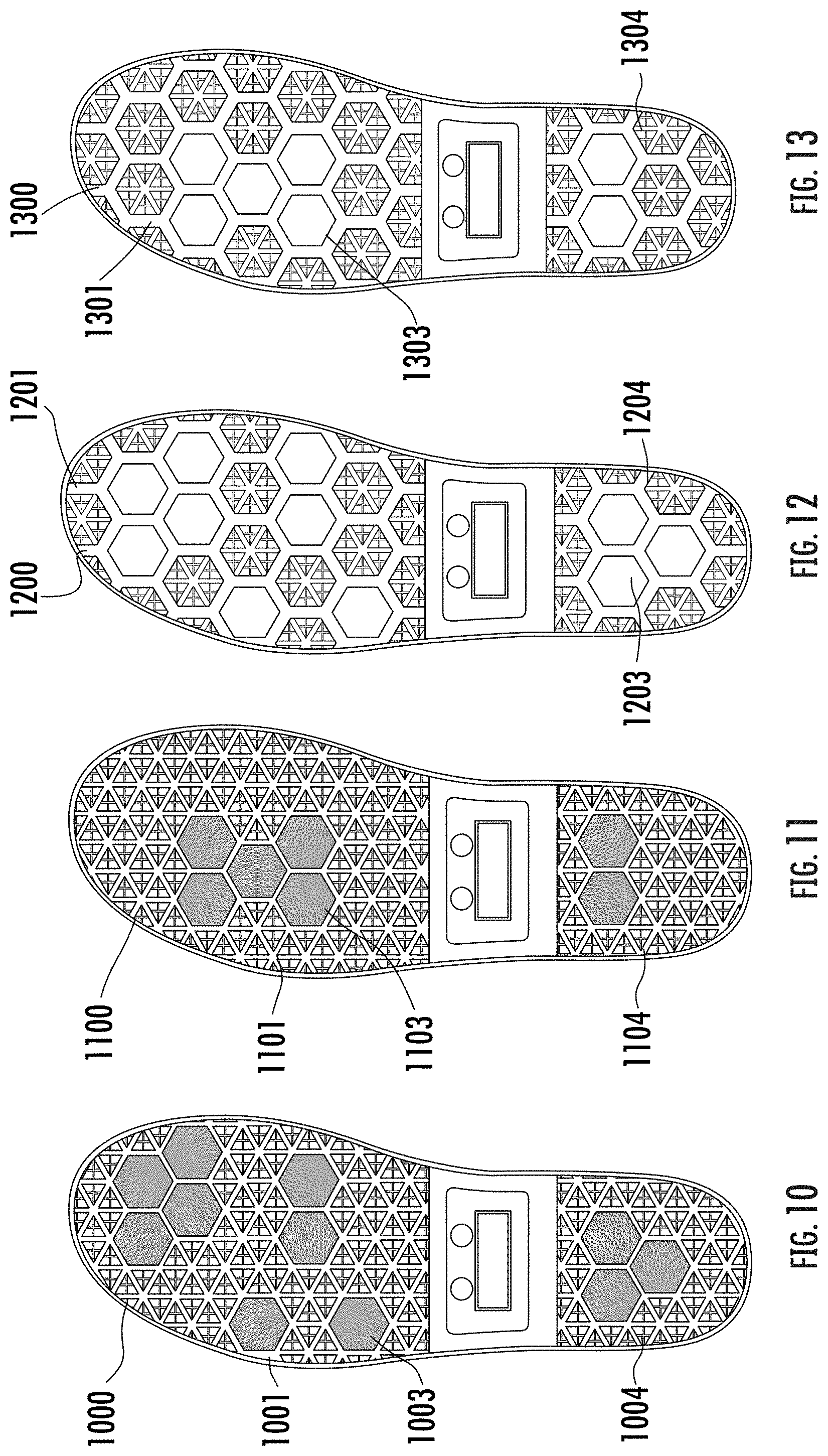
[0128] Referring now to FIGS. 10-13, example outsoles in accordance with the present disclosure are shown. In particular, example testing may be conducted on these example outsoles, which indicates that various embodiments of the present disclosure improve slip resistance of outsoles.
[0129] In FIG. 10, a plurality of first resistance elements 1003 and a plurality of second resistance elements 1004 may be disposed on the outer surface 1001 of the base 1000. Similarly, in FIG. 11, a plurality of first resistance elements 1103 and a plurality of second resistance elements 1104 may be disposed on the outer surface 1101 of the base 1100. Comparing FIG. 10 with FIG. 11, it can be seen that there are more first resistance elements disposed on the outer surface 1001 of the base 1000 than those disposed on the outer surface 1101 of the base 1100.
[0130] In FIG. 12, a plurality of first resistance elements 1203 and a plurality of second resistance elements 1204 may be disposed on the outer surface 1201 of the base 1200. Similarly, in FIG. 13, a plurality of first resistance elements 1303 and a plurality of second resistance elements 1304 may be disposed on the outer surface 1301 of the base 1300. Comparing FIG. 12 with FIG. 13, it can be seen that there are more first resistance elements disposed on the outer surface 1201 of the base 1200 than those disposed on the outer surface 1301 of the base 1300.
[0131] Example testing results of example outsoles embodying features from FIGS. 10-13 are summarized in TABLE 1 below.
TABLE-US-00001 TABLE 1 Example Testing Results Testing Item Required A B C D Dry Ice Static CoF Static CoF .gtoreq. 0.40 0.50 0.50 0.42 0.41 Dynamic 0.21 0.20 0.23 0.21 CoF Wet Icy Static CoF 0.51 0.51 0.48 0.37 Dynamic 0.16 0.15 0.14 0.21 CoF Surface 1 (Forefoot) .gtoreq.0.32 0.50 0.51 0.51 0.47 Surface 1 (Heel) .gtoreq.0.28 0.40 0.41 0.47 0.38 Surface 2 (Forefoot) .gtoreq.0.18 0.20 0.21 0.22 0.24 Surface 2 (Heel) .gtoreq.0.13 0.20 0.23 0.21 0.19
[0132] In TABLE 1, Column A indicates example testing results on an example outsole embodying features as shown in FIG. 10. Column B indicates example testing results on an example outsole embodying features as shown in FIG. 11. Column C indicates example testing results on an example outsole embodying features as shown in FIG. 12. Column D indicates example testing results on an example outsole embodying features as shown in FIG. 13.
[0133] As shown in TABLE 1, for each example outsole, dry icy slip resistance performance (including dynamic coefficient of friction and static coefficient of friction on a dry and icy surface) of each outsole are tested. Wet icy slip resistance performance (including dynamic coefficient of friction and static coefficient of friction on a wet and icy surface) of each outsole are also tested. The term "dynamic coefficient of friction" refers to the coefficient of friction when the wearer is moving on the surface, and the term "static coefficient of friction" refers to the coefficient of friction when the wearer is standing on the surface.
[0134] In addition, and as shown in TABLE 1, for each example outsole, additional example surface testing may be conducted, including testing on Surface 1 and testing on Surface 2. In this regard, Surface 1 may include ceramic tile flow lauryl sulphate, and Surface 2 may include steel substrate with glycerol. For each surface testing, both the circumstance of sliding of the heel area of the outsole ("heel") and the circumstance of sliding of the forefoot area of the outsole ("forefoot") are tested.
[0135] As shown in TABLE 1, all example outsoles pass requirements as shown in the Column Required. Further, comparing Column A with Column B, it can be seen that the incorporation of additional first resistance elements may improve the slip resistance of the example outsole on dry, icy surface in accordance with the present disclosure. In addition, by comparing Column A with Column C (as well as comparing Column B with Column D), it can be seen that the resistance elements and various configurations that they formed in accordance with various embodiments of the present disclosure may affect slip resistance performance of an example outsole. For example, TABLE 1 illustrates that the addition of the first type configuration as described above may improve the slip resistance performance on wet icy surface.
[0136] It is to be understood that the disclosure is not to be limited to the specific embodiments disclosed, and that modifications and other embodiments are intended to be included within the scope of the appended claims. Although specific terms are employed herein, they are used in a generic and descriptive sense only and not for purposes of limitation, unless described otherwise.
* * * * *
D00000
D00001
D00002
D00003
D00004
D00005
D00006
D00007
D00008
D00009
D00010
D00011
D00012

D00013
XML
uspto.report is an independent third-party trademark research tool that is not affiliated, endorsed, or sponsored by the United States Patent and Trademark Office (USPTO) or any other governmental organization. The information provided by uspto.report is based on publicly available data at the time of writing and is intended for informational purposes only.
While we strive to provide accurate and up-to-date information, we do not guarantee the accuracy, completeness, reliability, or suitability of the information displayed on this site. The use of this site is at your own risk. Any reliance you place on such information is therefore strictly at your own risk.
All official trademark data, including owner information, should be verified by visiting the official USPTO website at www.uspto.gov. This site is not intended to replace professional legal advice and should not be used as a substitute for consulting with a legal professional who is knowledgeable about trademark law.