Electronic Cigarette And Method For Manufacturing Component Thereof
Yuan; Guolin
U.S. patent application number 16/376147 was filed with the patent office on 2020-10-08 for electronic cigarette and method for manufacturing component thereof. The applicant listed for this patent is Ygreen Inc.. Invention is credited to Guolin Yuan.
| Application Number | 20200315258 16/376147 |
| Document ID | / |
| Family ID | 1000004038485 |
| Filed Date | 2020-10-08 |


View All Diagrams
| United States Patent Application | 20200315258 |
| Kind Code | A1 |
| Yuan; Guolin | October 8, 2020 |
ELECTRONIC CIGARETTE AND METHOD FOR MANUFACTURING COMPONENT THEREOF
Abstract
The present application discloses an electronic cigarette. The electronic cigarette comprises a mouthpiece and a tank. The tank is coupled to the mouth piece. The tank comprises a cartridge, an atomizer, a base and an adapter. The cartridge is made of glass and comprises an air duct, an oil cup, and a plate comprising at least one hole and coupled between the air duct and the oil cup. The atomizer is coupled to the oil cup. The base is coupled to the oil cup. The adapter is coupled to the base. A method for manufacturing the aforementioned cartridge is also disclosed. The method comprises welding the air duct and the plate; welding a lower oil cup of the oil cup with the plate; and welding an upper oil cup of the oil cup with the lower oil cup.
| Inventors: | Yuan; Guolin; (Walnut, CA) | ||||||||||
| Applicant: |
|
||||||||||
|---|---|---|---|---|---|---|---|---|---|---|---|
| Family ID: | 1000004038485 | ||||||||||
| Appl. No.: | 16/376147 | ||||||||||
| Filed: | April 5, 2019 |
| Current U.S. Class: | 1/1 |
| Current CPC Class: | A24F 47/008 20130101 |
| International Class: | A24F 47/00 20060101 A24F047/00 |
Claims
1. An electronic cigarette, comprising: a mouthpiece; and a tank coupled to the mouth piece, wherein the tank comprises: a cartridge made of glass and comprising: an air duct; an oil cup; and a plate comprising at least one hole and coupled between the air duct and the oil cup: an atomizer coupled to the oil cup: a base coupled to the oil cup; and an adapter coupled to the base.
2. The electronic cigarette as claimed in claim 1, wherein the air duct and the plate are molded integrally.
3. The electronic cigarette as claimed in claim 1, wherein the plate and the oil cup are molded integrally.
4. The electronic cigarette as claimed in claim 1, wherein the plate is threaded with the oil cup.
5. The electronic cigarette as claimed in claim 4, wherein an inner surface of the oil cup comprises infernal thread, a side surface of the plate comprises external thread.
6. The electronic cigarette as claimed in claim I, wherein the oil cup comprises an upper oil cup and a lower oil cup, the atomizer is threaded with the lower oil cup.
7. The electronic cigarette as claimed in claim 6, wherein an inner surface of the lower oil cup comprises internal thread, an outer surface of the atomizer comprises external thread.
8. The electronic cigarette as claimed in claim 7, wherein the atomizer comprises a connector, an outer case and a coil, the outer case comprises external thread.
9. The electronic cigarette as claimed in claim 1, wherein the tank further comprises a sealer coupled between the plate and the atomizer.
10. The electronic cigarette as claimed in claim 1, wherein the lank further comprises a tank fixer coupled to the mouthpiece.
11. The electronic cigarette as claimed in claim 10, wherein the tank fixer comprises a buckle.
12. The electronic cigarette as claimed in claim 10. wherein the mouthpiece comprises a nozzle and a mouthpiece fixer.
13. The electronic cigarette as claimed in claim 12, wherein the tank is coupled to the mouthpiece via coupling the tank fixer to the mouthpiece fixer.
14. The electronic cigarette as claimed in claim 12. wherein the mouthpiece further comprises a sealer coupled to an inner surface of the nozzle.
15. The electronic cigarette as claimed in claim 1, wherein the plate comprises three holes.
16. The electronic cigarette as claimed in claim 1, wherein the tank further comprises a sealer coupled between the base and the adapter.
17. The electronic cigarette as claimed in claim 16, further comprises a supporter coupled to the sealer.
18. A method for manufacturing the cartridge of claim 1 comprising: welding the air duct and the plate; welding a lower oil cup of the oil cup with the plate; and welding an upper oil cup of the oil cup with the lower oil cup.
19. The method for manufacturing the cartridge of claim 18, wherein before welding the air duct and the plate, the method further comprises automated manufacturing the air duct and the plate.
20. The method for manufacturing the cartridge of claim 18, wherein before welding the lower oil cup of the oil cup with the plate, the method further comprises automated manufacturing the lower oil cup and the upper lower tube.
Description
TECHNICAL FIELD OF THE INVENTION
[0001] The present application generally relates to electronic cigarette, and more particularly, to an electronic cigarette and a method for manufacturing component thereof.
BACKGROUND OF THE INVENTION
[0002] Current electronic cigarettes generally utilize brass as material for cartridge. The main processing technology is turning. However, it is necessary to add more lead in the brass for better turning, which may affect human health. In addition, subsequent surface treatments such as gold electroplating or tin-cobalt alloy electroplating are required after turning, increasing the heavy metal content which may be absorbed into human body.
[0003] Plastic is also utilized for manufacturing cartridge. However, the plastic may melt due to its low melting point. Specifically, the atomizing process requires a temperature of 250.degree. C.-300.degree. C. but the melting point of plastic is generally around 250.degree. C. As such, the plastic may melt if used improperly, causing other risks.
[0004] Moreover, current atomizer is installed with the cartridge via adhesive. However, the toxic material may also be released if the adhesive is melted due to overheat.
[0005] Therefore, a need remains for an electronic cigarette and a method for manufacturing component thereof to provide a more harmless product for hum at body.
SUMMARY OF THE INVENTION
[0006] The present application discloses an electronic cigarette and a method for manufacturing component thereof to provide a more harmless product for human body.
[0007] The electronic cigarette comprises a mouthpiece and a tank. The tank is coupled to the mouth piece. The tank comprises a cartridge, an atomizer, a base and an adapter. The cartridge is made of glass and comprises an air duct, an oil cup, and a plate comprising at least one hole and coupled between the air duct and the oil cup. The atomizer is coupled to the oil cup. The base is coupled to the oil cup. The adapter is coupled to the base.
[0008] In various exemplary embodiments, the air duet and the plate are molded integrally.
[0009] According to an exemplary embodiment of the electronic cigarette, the plate and the oil cup are molded integrally.
[0010] According to the other exemplary embodiment, the plate is threaded with the oil cup. Specifically, an inner surface of the oil cup comprises internal thread, a side surface of the plate comprises external thread.
[0011] In various exemplary embodiments, the oil cup comprises an upper oil cup and a lower oil cup. the atomizer is threaded with the lower oil cup. In detail, an inner surface of the lower oil cup comprises internal thread, an outer surface of the atomizer comprises external thread. The atomizer comprises a connector, an outer case and a coil, the outer case comprises external thread.
[0012] In various exemplary embodiments, the tank further comprises a sealer coupled between the plate and the atomizer.
[0013] In various exemplary embodiments, the lank further comprises a tank fixer coupled to the mouthpiece and comprising a buckle. Specifically, the mouthpiece comprises a nozzle and a mouthpiece fixer. The tank is coupled to the mouthpiece via coupling the tank fixer to the mouthpiece fixer. In addition, the mouthpiece further comprises a sealer coupled to an inner surface of the nozzle.
[0014] In various exemplary embodiments, the plate comprises three holes.
[0015] In various exemplary embodiments, the tank further comprises a sealer coupled between the base and the adapter. In addition, the electronic cigarette further comprises a supporter coupled to the sealer.
[0016] A method for manufacturing the aforementioned cartridge is also disclosed. The method comprises welding the air duct and the plate: welding a lower oil cup of the oil cup with the plate; and welding an upper oil cup of the oil cup with the lower oil cup.
[0017] In various exemplary embodiments, before welding the air duct and the plate, the method further comprises automated manufacturing the air duct and the plate.
[0018] In various exemplary embodiments, before welding the lower oil cup of the oil cup with the plate, the method further comprises automated manufacturing the lower oil cup and the upper lower tube.
[0019] Based on the above, the present application utilizes glass as material for manufacturing the cartridge, decreasing the likelihood of inhaling toxic substances and maintaining the pure taste, furthermore, the glass may increase the fluidity compared to metal material. In addition, the atomizer can be coupled to the cartridge via threading, eliminating the utilization of the adhesive.
[0020] Meanwhile, since the present application automated manufactures the air duct, plate and the oil cup. the temperature, size and time for welding the glass can be controlled. As such, the problems of instability of overall size and oil size can be reduced. Furthermore, the present application may also eliminate the trouble of glass deformation.
[0021] Numerous other advantages and features of the present application will become readily apparent from the following detailed description of disclosed embodiments, from the claims and from the accompanying drawings.
BRIEF DESCRIPTION OF THE DRAWINGS
[0022] The objects, features and advantages of the present application will lie more readily appreciated upon reference to the following disclosure when considered in conjunction with the accompanying drawings, wherein like reference numerals are used to identify identical components in the various views. and wherein reference numerals with alphabetic characters arc utilized to identify additional types, instantiations or variations of a selected component embodiment in the various views, in which:
[0023] FIG. 1 is a perspective view of an electronic cigarette of a first embodiment.
[0024] FIG. 2 is an explosive view of the electronic cigarette of the first embodiment.
[0025] FIG. 3 is a cross-sectional view of the electronic cigarette of the first embodiment.
[0026] FIG. 4A is a perspective view of a cartridge of the electronic cigarette of the first embodiment.
[0027] FIG. 4B is a cross-sectional view through a FIG. 4B-FIG. 4B line of the cartridge of FIG. 4A.
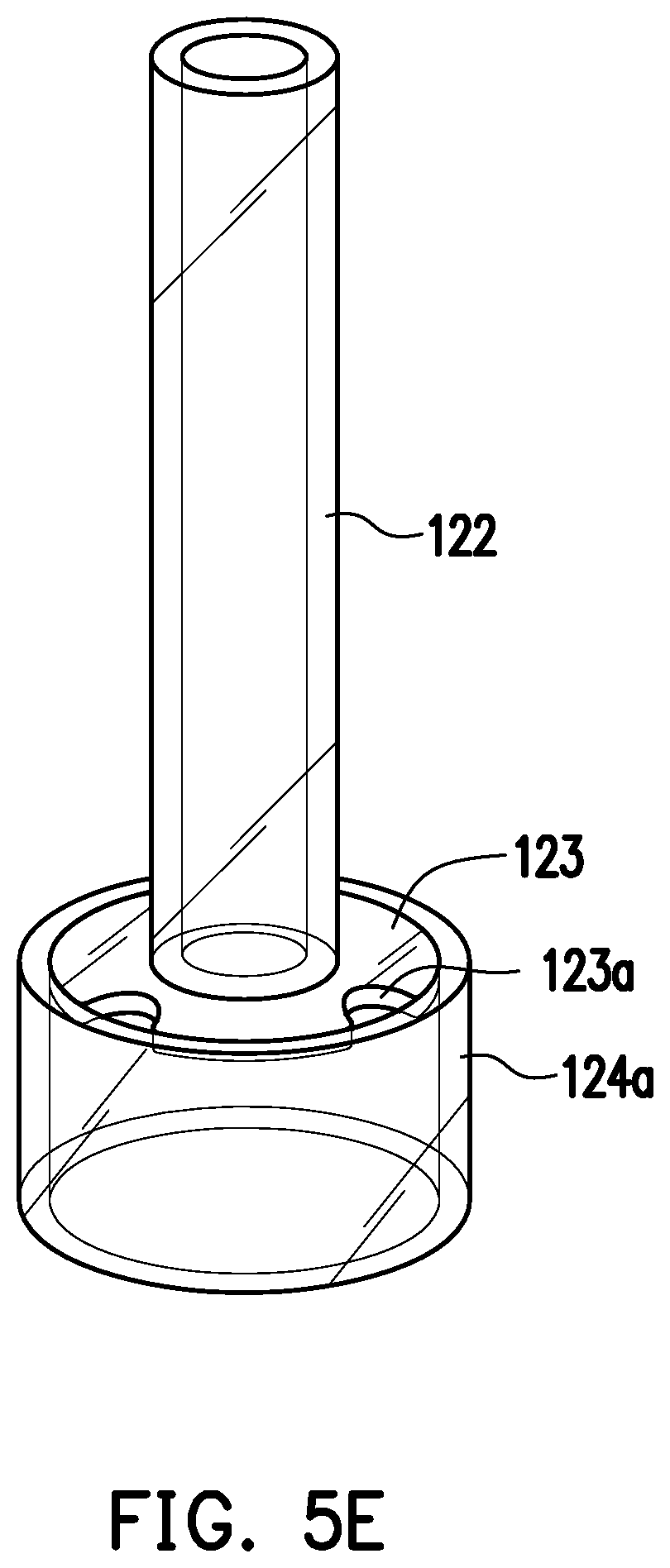
[0028] FIGS. 5A-5G are perspective views showing the manufacturing process of the cartridge of the electronic cigarette of the first embodiment.
[0029] FIG. 6 is a perspective view showing the mechanism of coupling the electronic cigarette of the first embodiment to a supporter.
[0030] FIG. 7A is a perspective view of an electronic cigarette of a second embodiment.
[0031] FIG. 7B is a perspective view of a cartridge of the electronic cigarette of the second embodiment.
[0032] FIG. 7C is a cross-sectional view of the cartridge of the electronic cigarette of the second embodiment.
[0033] FIG. 8 is a cross-sectional view of a cartridge of an electronic cigarette of a third embodiment.
[0034] FIGS. 9A-9B shows the experimental data between different material of cartridge.
DETAILED DESCRIPTION OF DISCLOSED EMBODIMENTS
[0035] Reference will now be made in detail to the present representative embodiments of the present application, examples of which are illustrated in the accompanying drawings. Wherever possible, the same reference numbers are used in the drawings and the description to refer to the same or like parts.
[0036] FIG. 1 is a perspective view of an electronic cigarette 100 of a first embodiment. FIG. 2 is an explosive view of the electronic cigarette 100 of the first embodiment. FIG. 3 is a cross-sectional view of the electronic cigarette 100 of the first embodiment.
[0037] Referring to FIGS. 1-3, the electronic cigarette 100 of the present application comprises a mouthpiece 110 and a tank 120. The mouthpiece 110 comprises a nozzle 111, a fixer 112 and a sealer 113. The fixer 112 is used for coupling the mouthpiece 110 and the tank 120 and will be described later. The sealer 113 is coupled with the nozzle 111.
[0038] The tank 120 comprises a fixer 121, a cartridge, a sealer 125, an atomizer 126, a base 127, a sealer 128 and an adapter 129.
[0039] The fixer 121 is coupled to the mouthpiece 110. Specifically, the fixer 121 comprises a buckle 121a, which is capable of engaging with the fixer 112 located inside the nozzle 111. The fixer 121 can comprises another mechanism fin- engaging with the fixer 112 such as via threading, the present application is not limited thereto.
[0040] The cartridge is made of glass and comprises an air duct 122, a plate 123 and an oil cup 124. The oil cup 124 comprises a lower oil cup 124a (referring to FIG. 5G) and an upper oil cup 124b (referring to FIG. 5G). The detail of the cartridge will be described with FIGS. 4A-4B and FIGS. 5A-5G.
[0041] The sealer 125 is coupled between the plate 123 and the atomizer 126 for better engagement.
[0042] The atomizer 126 comprises an outer case 126a, a coil 126b and a connector 126c.
[0043] The base 127 comprises a plate 127a, an external thread portion 127b and a mesh pattern portion 127c. The plate 127a is coupled between the external thread portion 127b and the mesh pattern portion 127c. The external thread portion 127b is capable of engaging with the battery. In present application, the electronic cigarette 100 is charged by threading the external thread portion 127b of the base 127 with the battery. However, the present application is not limited thereto. The electronic cigarette 100 can he charged via other mechanism as long as the electronic cigarette 100 can be electrically connected to the battery. The mesh pattern portion 127c is capable of providing the better engagement of the base 127 and the oil cup 124 by increasing the friction.
[0044] The sealer 128 is coupled to the base 127. The adapter 129 is coupled to the base 127 via the sealer 128. The adapter 129 is electrically connected to the coil 126b of the atomizer 126 for atomization.
[0045] FIG. 4A is a perspective view of a cartridge of the electronic cigarette 100 of the first embodiment. FIG. 4B is a cross-sectional view through a FIG. 4B-F1G. 4B line of the cartridge of FIG. 4A. FIGS. 5A-5G are perspective views showing the manufacturing process of the cartridge of the electronic cigarette 100 of the first embodiment.
[0046] To prevent confusion, FIGS. 4A-4B illustrate the cartridge as light-impermeable. However, since the cartridge is made of glass, the cartridge of the present application should be presented as shown in FIGS. 5A-5G.
[0047] As shown in FIGS. 4A-5C, the cartridge comprises the air duct 122, the plate 123 and the oil cup 124. The air duct 122 is a tube. The plate 123 comprises at least one hole 123a and one central hole 123b. In the present application, the plate 123 comprises three holes 123a as an example, but the present application is not limited thereto. As shown in FIG. 50, the air duct 122 is welded with the plate 123.
[0048] Referring to FIGS. 5D-5E, the lower oil cup 124a is welded with the plate 123. Specifically, the plate 123 is welded to an internal surface of the lower oil cup 124a, allowing the substance to pass through the holes 123a and into the lower oil cup 124a.
[0049] Referring to FIGSD. 5F-5G, the upper oil cup 124b is welded with the lower oil cup 124a.
[0050] The present application utilizes automated manufacturing process to manufacture the air duct 122, the plate 123, the lower oil cup 124a and the upper oil cup 124b.
[0051] FIG. 6 is a perspective view showing the mechanism of coupling the electronic cigarette 100 of the first embodiment to a supporter 130.
[0052] Referring to FIG. 6, the electronic cigarette 100 of the present application may further comprises the supporter 130. The supporter 130 is capable of supporting the electronic cigarette 100.
[0053] FIG. 7A is a perspective view of an electronic cigarette 200 of a second embodiment. FIG. 7B is a perspective view of a cartridge of the electronic cigarette 200 of the second embodiment. FIG. 7C is a cross-sectional view of the cartridge of the electronic cigarette 200 of the second embodiment.
[0054] Referring to FIGS. 7A-7C, the electronic cigarette 200 comprises a mouthpiece 210 and a tank 220. The tank 220 comprises a fixer (not separately illustrated), a cartridge, a sealer (not separately illustrated), an atomizer 226, a base 227, a sealer (net separately illustrated) and an adapter 229.
[0055] The cartridge comprises an air duct 222, a plate 223 and an oil cup 224. Tire plate 223 comprises holes 223a.
[0056] The base 227 comprises a plate 227a, an external thread portion 227b and a mesh pattern portion 227c.
[0057] The difference between the electronic cigarette 100 and the electronic cigarette 200 is the structure of the atomizer and the low er oil cup.
[0058] Referring to FIGS. 7A-7C with reference to FIG. I, the atomizer 226 comprises an external thread and the lower oil cup 224a comprises internal thread. The atomizer 226 is threaded with the lower oil cup 224a via coupling the external thread of the atomizer 226 to the internal thread of the lower oil cup 224a.
[0059] FIG. 8 is a cross-sectional view of a cartridge of an electronic cigarette 300 of a third embodiment.
[0060] The cartridge comprises an air duct 322, a plate 323 and an oil cup 324. The plate 323 comprises at least one hole 323a and external thread. The oil cup 324 comprises a lower oil cup 324a and an upper oil cup 324b. The lower oil cup 324a comprises an internal thread for the external thread of the plate 323 and an internal thread for the atomizer. The difference between the cartridge of the electronic cigarette 300 and the cartridge of the electronic cigarette 200 is that the plate 323 is threaded to the lower oil cup 324a rather than being welded.
[0061] FIGS. 9A-9B shows the experimental data between different material of cartridge.
[0062] Referring to FIG. 9A. the specimen in FIG. 9A is general brass of a mouthpiece for electronic cigarette. The test is examined with reference to IEC62321-4:2013+A1:2017, IEC62321-5:2013, IEC62321-7-1:2015 and is analyzed by ICP-OHS and UV-Vis.
[0063] 1 mg/kg is equal to 1 ppm and 0.0001%. MDL in the chart means method detection limit. ND in the chart means not detected or less than MDL. "-" in the chart means not regulated.
[0064] Referring to FIG. 9B, the specimen in FIG. 9B is a piece of glass. The test is examined with reference to IEC62321-4:2013+AMD1:2017, IEC62321-5:2013, IEC62321-7-2:2017, IEC62321-6:2015, IEC62321-8-1:2017 and is analyzed by ICP-OES, AAS, UV-Vis and GC-MS.
[0065] 1 mg/kg is equal to 0.0001%. MDL in the chart means method detection limit. ND in the chart means not detected or less than MDL. "-" in the chart means not regulated.
[0066] Based on the above, the present application utilizes glass as material for manufacturing the cartridge, decreasing the likelihood of inhaling toxic substances and maintaining the pure taste as shown in the test results. Furthermore, the glass may increase the fluidity compared to metal material.
[0067] In addition, the atomizer and/or the plate of the cartridge can be coupled to the cartridge via threading, eliminating the utilization of the adhesive, which also brings toxic substances if it is overheated.
[0068] Meanwhile, since the present application automated manufactures the air duct, plate and the oil cup, the temperature, size and time for welding the glass can be controlled. As such, the problems of instability of overall size and oil size can be reduced Furthermore, the present application may also eliminate the trouble of glass deformation.
[0069] If will be apparent to those skilled in the art that various modifications and variations can be made to the structure of the present application without departing from the scope or spirit of the present application. In view of the foregoing, it is intended that the present application cover modifications and variations of this application provided they fall within the scope of the following claims and their equivalents.
* * * * *
D00000
D00001
D00002
D00003
D00004
D00005
D00006
D00007
D00008
D00009
D00010
D00011
D00012

D00013

D00014

D00015

D00016

XML
uspto.report is an independent third-party trademark research tool that is not affiliated, endorsed, or sponsored by the United States Patent and Trademark Office (USPTO) or any other governmental organization. The information provided by uspto.report is based on publicly available data at the time of writing and is intended for informational purposes only.
While we strive to provide accurate and up-to-date information, we do not guarantee the accuracy, completeness, reliability, or suitability of the information displayed on this site. The use of this site is at your own risk. Any reliance you place on such information is therefore strictly at your own risk.
All official trademark data, including owner information, should be verified by visiting the official USPTO website at www.uspto.gov. This site is not intended to replace professional legal advice and should not be used as a substitute for consulting with a legal professional who is knowledgeable about trademark law.