Identifying Mechanical Impedance Of An Electromagnetic Load Using Least-mean-squares Filter
MARCHAIS; Emmanuel ; et al.
U.S. patent application number 16/559238 was filed with the patent office on 2020-10-01 for identifying mechanical impedance of an electromagnetic load using least-mean-squares filter. This patent application is currently assigned to Cirrus Logic International Semiconductor Ltd.. The applicant listed for this patent is Cirrus Logic International Semiconductor Ltd.. Invention is credited to Eric LINDEMANN, Emmanuel MARCHAIS, Pablo PESO PARADA.
| Application Number | 20200313654 16/559238 |
| Document ID | / |
| Family ID | 1000004335919 |
| Filed Date | 2020-10-01 |


View All Diagrams
| United States Patent Application | 20200313654 |
| Kind Code | A1 |
| MARCHAIS; Emmanuel ; et al. | October 1, 2020 |
IDENTIFYING MECHANICAL IMPEDANCE OF AN ELECTROMAGNETIC LOAD USING LEAST-MEAN-SQUARES FILTER
Abstract
A method for identifying a mechanical impedance of an electromagnetic load may include generating a waveform signal for driving an electromagnetic load and, during driving of the electromagnetic load by the waveform signal or a signal derived therefrom, receiving a current signal representative of a current associated with the electromagnetic load and a back electromotive force signal representative of a back electromotive force associated with the electromagnetic load. The method may also include implementing an adaptive filter to identify parameters of the mechanical impedance of the electromagnetic load, wherein an input of a coefficient control for adapting coefficients of the adaptive filter is a first signal derived from the back electromotive force signal and a target of the coefficient control for adapting coefficients of the adaptive filter is a second signal derived from the current signal.
| Inventors: | MARCHAIS; Emmanuel; (Austin, TX) ; PESO PARADA; Pablo; (Maidenhead, GB) ; LINDEMANN; Eric; (Boulder, CO) | ||||||||||
| Applicant: |
|
||||||||||
|---|---|---|---|---|---|---|---|---|---|---|---|
| Assignee: | ; Cirrus Logic International
Semiconductor Ltd. Edinburgh GB |
||||||||||
| Family ID: | 1000004335919 | ||||||||||
| Appl. No.: | 16/559238 | ||||||||||
| Filed: | September 3, 2019 |
Related U.S. Patent Documents
| Application Number | Filing Date | Patent Number | ||
|---|---|---|---|---|
| 62826299 | Mar 29, 2019 | |||
| Current U.S. Class: | 1/1 |
| Current CPC Class: | H02N 2/06 20130101; G06F 3/016 20130101; H03H 7/12 20130101; H03H 17/06 20130101; G01H 15/00 20130101 |
| International Class: | H03H 17/06 20060101 H03H017/06; H03H 7/12 20060101 H03H007/12; G01H 15/00 20060101 G01H015/00; H02N 2/06 20060101 H02N002/06; G06F 3/01 20060101 G06F003/01 |
Claims
1. A system for identifying a mechanical impedance of an electromagnetic load comprising: a signal generator configured to generate a waveform signal for driving an electromagnetic load; and mechanical impedance identity circuitry configured to: during driving of the electromagnetic load by the waveform signal or a signal derived therefrom, receive: a current signal representative of a current associated with the electromagnetic load; and a back electromotive force signal representative of a back electromotive force associated with the electromagnetic load; and implement an adaptive filter to identify parameters of the mechanical impedance of the electromagnetic load, wherein: an input of a coefficient control for adapting coefficients of the adaptive filter is a first signal derived from the back electromotive force signal; and a target of the coefficient control for adapting coefficients of the adaptive filter is a second signal derived from the current signal.
2. The system of claim 1, wherein the mechanical impedance identity circuitry implements the coefficient control with a least-mean-squares algorithm.
3. The system of claim 1, wherein the adaptive filter comprises a finite impulse response filter.
4. The system of claim 3 wherein: the mechanical impedance identity circuitry applies the adaptive filter to the first signal to generate an adaptive filter output; and the coefficient control receives the first signal and a signal derived from the adaptive filter output as its inputs.
5. The system of claim 3 wherein: the mechanical impedance identity circuitry is further configured to apply the adaptive filter to the first signal to generate an adaptive filter output; the mechanical impedance identity circuitry is further configured to generate an error signal based on the difference between the adaptive filter output and the second signal; and the coefficient control receives the first signal and the error signal as its inputs.
6. The system of claim 1, wherein the mechanical impedance identity circuitry generates the first signal by band-pass filtering the back electromotive force signal at frequencies near a resonance frequency of the electromagnetic load.
7. The system of claim 1, wherein the mechanical impedance identity circuitry generates the first signal by filtering the back electromotive force with an integrator filter.
8. The system of claim 1, wherein the mechanical impedance identity circuitry generates the first signal by band-pass filtering the current signal at frequencies near a resonance frequency of the electromagnetic load.
9. The system of claim 1, wherein the mechanical impedance identity circuitry generates the first signal by filtering the back electromotive force with a moving average filter.
10. The system of claim 1, wherein the electromagnetic load comprises a haptic transducer.
11. The system of claim 1, wherein the electromagnetic load comprises a linear resonant actuator.
12. The system of claim 1, wherein the mechanical impedance identity is configured to determine parameters of a mechanical impedance of the electromagnetic load based on coefficients of the adaptive filter.
13. The system of claim 12, wherein the parameters of a mechanical impedance comprise a mechanical resistance of the electromagnetic load at resonance, a resonant frequency of the electromagnetic load, and a quality factor of the electromagnetic load.
14. A method for identifying a mechanical impedance of an electromagnetic load comprising: generating a waveform signal for driving an electromagnetic load; during driving of the electromagnetic load by the waveform signal or a signal derived therefrom, receiving: a current signal representative of a current associated with the electromagnetic load; and a back electromotive force signal representative of a back electromotive force associated with the electromagnetic load; and implementing an adaptive filter to identify parameters of the mechanical impedance of the electromagnetic load, wherein: an input of a coefficient control for adapting coefficients of the adaptive filter is a first signal derived from the back electromotive force signal; and a target of the coefficient control for adapting coefficients of the adaptive filter is a second signal derived from the current signal.
15. The method of claim 14, further comprising implementing the coefficient control with a least-mean-squares algorithm.
16. The method of claim 14, wherein the adaptive filter comprises a finite impulse response filter.
17. The method of claim 16, further comprising applying the adaptive filter to the first signal to generate an adaptive filter output, wherein the coefficient control receives the first signal and a signal derived from the adaptive filter output as its inputs.
18. The method of claim 16, further comprising: applying the adaptive filter to the first signal to generate an adaptive filter output; and generating an error signal based on the difference between the adaptive filter output and the second signal; wherein the coefficient control receives the first signal and the error signal as its inputs.
19. The method of claim 14, further comprising generating the first signal by band-pass filtering the back electromotive force signal at frequencies near a resonance frequency of the electromagnetic load.
20. The method of claim 14, further comprising generating the first signal by filtering the back electromotive force with an integrator filter.
21. The method of claim 14, further comprising generating the first signal by band-pass filtering the current signal at frequencies near a resonance frequency of the electromagnetic load.
22. The method of claim 14, further comprising generating the first signal by filtering the back electromotive force with a moving average filter.
23. The method of claim 14, wherein the electromagnetic load comprises a haptic transducer.
24. The system of claim 14, wherein the electromagnetic load comprises a linear resonant actuator.
25. The method of claim 14, further comprising determining parameters of a mechanical impedance of the electromagnetic load based on coefficients of the adaptive filter.
26. The method of claim 25, wherein the parameters of a mechanical impedance comprise a mechanical resistance of the electromagnetic load at resonance, a resonant frequency of the electromagnetic load, and a quality factor of the electromagnetic load.
27. A host device comprising: an electromagnetic load; and a system for identifying a mechanical impedance of the electromagnetic load comprising: a signal generator configured to generate a waveform signal for driving an electromagnetic load; and mechanical impedance identity circuitry configured to: during driving of the electromagnetic load by the waveform signal or a signal derived therefrom, receive: a current signal representative of a current associated with the electromagnetic load; and a back electromotive force signal representative of a back electromotive force associated with the electromagnetic load; and implement an adaptive filter to identify parameters of the mechanical impedance of the electromagnetic load, wherein: an input of a coefficient control for adapting coefficients of the adaptive filter is a first signal derived from the back electromotive force signal; and a target of the coefficient control for adapting coefficients of the adaptive filter is a second signal derived from the current signal.
Description
RELATED APPLICATION
[0001] The present disclosure claims priority to U.S. Provisional Patent Application Ser. No. 62/826,299, filed Mar. 29, 2019, which is incorporated by reference herein in its entirety.
FIELD OF DISCLOSURE
[0002] The present disclosure relates in general to tracking and identifying a mechanical impedance of an electromagnetic load, for example, a haptic transducer.
BACKGROUND
[0003] Vibro-haptic transducers, for example linear resonant actuators (LRAs), are widely used in portable devices such as mobile phones to generate vibrational feedback to a user. Vibro-haptic feedback in various forms creates different feelings of touch to a user's skin, and may play increasing roles in human-machine interactions for modern devices.
[0004] An LRA may be modelled as a mass-spring electro-mechanical vibration system. When driven with appropriately designed or controlled driving signals, an LRA may generate certain desired forms of vibrations. For example, a sharp and clear-cut vibration pattern on a user's finger may be used to create a sensation that mimics a mechanical button click. This clear-cut vibration may then be used as a virtual switch to replace mechanical buttons.
[0005] FIG. 1 illustrates an example of a vibro-haptic system in a device 100. Device 100 may comprise a controller 101 configured to control a signal applied to an amplifier 102. Amplifier 102 may then drive a haptic transducer 103 based on the signal. Controller 101 may be triggered by a trigger to output to the signal. The trigger may for example comprise a pressure or force sensor on a screen or virtual button of device 100.
[0006] Among the various forms of vibro-haptic feedback, tonal vibrations of sustained duration may play an important role to notify the user of the device of certain predefined events, such as incoming calls or messages, emergency alerts, and timer warnings, etc. In order to generate tonal vibration notifications efficiently, it may be desirable to operate the haptic actuator at its resonance frequency.
[0007] The resonance frequency f.sub.0 of a haptic transducer may be approximately estimated as:
f 0 = 1 2 .pi. CM ( 1 ) ##EQU00001##
where C is the compliance of the spring system, and M is the equivalent moving mass, which may be determined based on both the actual moving part in the haptic transducer and the mass of the portable device holding the haptic transducer.
[0008] Due to sample-to-sample variations in individual haptic transducers, mobile device assembly variations, temporal component changes caused by aging, and use conditions such as various different strengths of a user gripping of the device, the vibration resonance of the haptic transducer may vary from time to time.
[0009] FIG. 2 illustrates an example of a linear resonant actuator (LRA) modelled as a linear system. LRAs are non-linear components that may behave differently depending on, for example, the voltage levels applied, the operating temperature, and the frequency of operation. However, these components may be modelled as linear components within certain conditions. In this example, the LRA is modelled as a third order system having electrical and mechanical elements. In particular, Re and Le are the DC resistance and coil inductance of the coil-magnet system, respectively; and Bl is the magnetic force factor of the coil. The driving amplifier outputs the voltage waveform V(t) with the output impedance Ro. The terminal voltage V.sub.T(t) may be sensed across the terminals of the haptic transducer. The mass-spring system 201 moves with velocity u(t).
[0010] In a system having an electromagnetic load such as an LRA, it may be desirable to determine the parameters that define an impedance of the electromagnetic load. Knowledge of such parameters may allow for optimization of playback of signals (e.g., playback of haptic waveforms) to the electromagnetic load. In addition, determination of electromagnetic load impedance may be valuable as it may allow for adapting of a playback signal to allow the playback signal to track changing parameters of the electromagnetic load.
[0011] An electromagnetic load such as an LRA may be characterized by its impedance Z.sub.Lra as seen as the sum of a coil impedance Z.sub.coil and a mechanical impedance Z.sub.mech:
Z.sub.Lra=Z.sub.coil+Z.sub.mech (2)
[0012] Coil impedance Z.sub.coil may in turn comprise a direct current (DC) resistance Re in series with an inductance Le:
Z.sub.coil=Re+sLe (3)
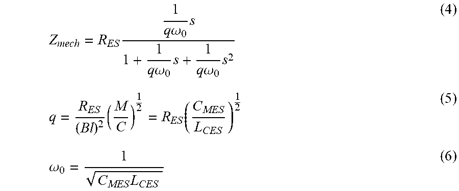
[0013] Mechanical impedance Z.sub.mech may be defined by three parameters including a resistance at resonance R.sub.ES, an angular resonant frequency .omega..sub.0 (e.g., .omega..sub.0=2.pi.f.sub.0), and a quality factor q. Or equivalently, mechanical impedance Z.sub.mech may be defined by three parameters including the resistance at resonance R.sub.ES, a capacitance C.sub.MES representing an electrical capacitance representative of an equivalent moving mass M of the spring system of haptic transducer, and inductance L.sub.CES representative of a compliance C of the spring system. The relationship among these quantities may be given by the following equations, in which s is the Laplace transform variable:
Z mech = R ES 1 q .omega. 0 s 1 + 1 q .omega. 0 s + 1 q .omega. 0 s 2 ( 4 ) q = R ES ( Bl ) 2 ( M C ) 1 2 = R ES ( C MES L CES ) 1 2 ( 5 ) .omega. 0 = 1 C MES L CES ( 6 ) ##EQU00002##
[0014] Traditional approaches for driving an LRA at resonance rely on detecting a time difference between zero crossings of the LRA's back electromotive force (back-EMF) and the load current or voltage. Such difference may then be used to adjust a period of a signal driven to the LRA. One disadvantage of this approach is its sensitivity to noise because all of the noise power is essentially aliased by an effective sampling rate at approximately two times the resonance frequency. Such approach may also suffer from slow convergence if a loop filter is used to reduce sensitivity to noise, because as a rule of thumb, bandwidth of the loop filter should be one-tenth of the effective sampling rate (or less). Further, using such approaches and LRA may be tri-stated at zero crossing events in order to allow a reading of back-EMF, which may result in a loss of drive duty cycle (e.g., maximum power from a driving amplifier may not be delivered to the LRA).
[0015] Existing approaches to determining a complex impedance may include using broadband noise to excite a system having an electromagnetic load. For example, using existing approaches, a Fast Fourier Transform of current and voltage waveforms associated with the electromagnetic load may be performed to determine impedance.
SUMMARY
[0016] In accordance with the teachings of the present disclosure, the disadvantages and problems associated with identifying a mechanical impedance of an electromagnetic load may be reduced or eliminated.
[0017] In accordance with embodiments of the present disclosure, a system for identifying a mechanical impedance of an electromagnetic load may include a signal generator configured to generate a waveform signal for driving an electromagnetic load and mechanical impedance identity circuitry. The mechanical impedance identity circuitry may be configured to, during driving of the electromagnetic load by the waveform signal or a signal derived therefrom, receive a current signal representative of a current associated with the electromagnetic load and a back electromotive force signal representative of a back electromotive force associated with the electromagnetic load. The mechanical impedance identity circuitry may also be configured to implement an adaptive filter to identify parameters of the mechanical impedance of the electromagnetic load, wherein an input of a coefficient control for adapting coefficients of the adaptive filter is a first signal derived from the back electromotive force signal and a target of the coefficient control for adapting coefficients of the adaptive filter is a second signal derived from the current signal.
[0018] In accordance with these and other embodiments of the present disclosure, a method for identifying a mechanical impedance of an electromagnetic load may include generating a waveform signal for driving an electromagnetic load and, during driving of the electromagnetic load by the waveform signal or a signal derived therefrom, receiving a current signal representative of a current associated with the electromagnetic load and a back electromotive force signal representative of a back electromotive force associated with the electromagnetic load. The method may also include implementing an adaptive filter to identify parameters of the mechanical impedance of the electromagnetic load, wherein an input of a coefficient control for adapting coefficients of the adaptive filter is a first signal derived from the back electromotive force signal and a target of the coefficient control for adapting coefficients of the adaptive filter is a second signal derived from the current signal.
[0019] In accordance with these and other embodiments of the present disclosure, a host device may include an electromagnetic load and system for identifying a mechanical impedance of the electromagnetic load. The system for identifying a mechanical impedance of the electromagnetic load may include a signal generator configured to generate a waveform signal for driving an electromagnetic load and mechanical impedance identity circuitry. The mechanical impedance identity circuitry may be configured to, during driving of the electromagnetic load by the waveform signal or a signal derived therefrom, receive a current signal representative of a current associated with the electromagnetic load and a back electromotive force signal representative of a back electromotive force associated with the electromagnetic load. The mechanical impedance identity circuitry may also be configured to implement an adaptive filter to identify parameters of the mechanical impedance of the electromagnetic load, wherein an input of a coefficient control for adapting coefficients of the adaptive filter is a first signal derived from the back electromotive force signal and a target of the coefficient control for adapting coefficients of the adaptive filter is a second signal derived from the current signal.
[0020] Technical advantages of the present disclosure may be readily apparent to one having ordinary skill in the art from the figures, description and claims included herein. The objects and advantages of the embodiments will be realized and achieved at least by the elements, features, and combinations particularly pointed out in the claims.
[0021] It is to be understood that both the foregoing general description and the following detailed description are examples and explanatory and are not restrictive of the claims set forth in this disclosure.
BRIEF DESCRIPTION OF THE DRAWINGS
[0022] A more complete understanding of the present embodiments and advantages thereof may be acquired by referring to the following description taken in conjunction with the accompanying drawings, in which like reference numbers indicate like features, and wherein:
[0023] FIG. 1 illustrates an example of a vibro-haptic system in a device, as is known in the art;
[0024] FIG. 2 illustrates an example of a Linear Resonant Actuator (LRA) modelled as a linear system, as is known in the art; and
[0025] FIG. 3 illustrates an example system for identifying mechanical impedance of an electromagnetic load, in accordance with embodiments of the present disclosure.
DETAILED DESCIPTION
[0026] The description below sets forth example embodiments according to this disclosure. Further example embodiments and implementations will be apparent to those having ordinary skill in the art. Further, those having ordinary skill in the art will recognize that various equivalent techniques may be applied in lieu of, or in conjunction with, the embodiment discussed below, and all such equivalents should be deemed as being encompassed by the present disclosure.
[0027] Various electronic devices or smart devices may have transducers, speakers, and acoustic output transducers, for example any transducer for converting a suitable electrical driving signal into an acoustic output such as a sonic pressure wave or mechanical vibration. For example, many electronic devices may include one or more speakers or loudspeakers for sound generation, for example, for playback of audio content, voice communications and/or for providing audible notifications.
[0028] Such speakers or loudspeakers may comprise an electromagnetic actuator, for example a voice coil motor, which is mechanically coupled to a flexible diaphragm, for example a conventional loudspeaker cone, or which is mechanically coupled to a surface of a device, for example the glass screen of a mobile device. Some electronic devices may also include acoustic output transducers capable of generating ultrasonic waves, for example for use in proximity detection type applications and/or machine-to-machine communication.
[0029] Many electronic devices may additionally or alternatively include more specialized acoustic output transducers, for example, haptic transducers, tailored for generating vibrations for haptic control feedback or notifications to a user. Additionally or alternatively an electronic device may have a connector, e.g., a socket, for making a removable mating connection with a corresponding connector of an accessory apparatus and may be arranged to provide a driving signal to the connector so as to drive a transducer, of one or more of the types mentioned above, of the accessory apparatus when connected. Such an electronic device will thus comprise driving circuitry for driving the transducer of the host device or connected accessory with a suitable driving signal. For acoustic or haptic transducers, the driving signal will generally be an analog time varying voltage signal, for example, a time varying waveform.
[0030] As previously mentioned, identifying a mechanical impedance of an electromagnetic load may be useful for some types of haptic application. In the present disclosure, and as described in greater detail below, a two-tone stimulus may be used to excite an electromagnetic load to provide four measurable parameters: an amplitude and phase of the electromagnetic load associated with each of the tones. Three of these four measureable parameters may then be chosen to determine the parameters (angular resonant frequency .omega..sub.0, quality factor q, and resistance at resonance R.sub.ES) of mechanical impedance Z.sub.mech.
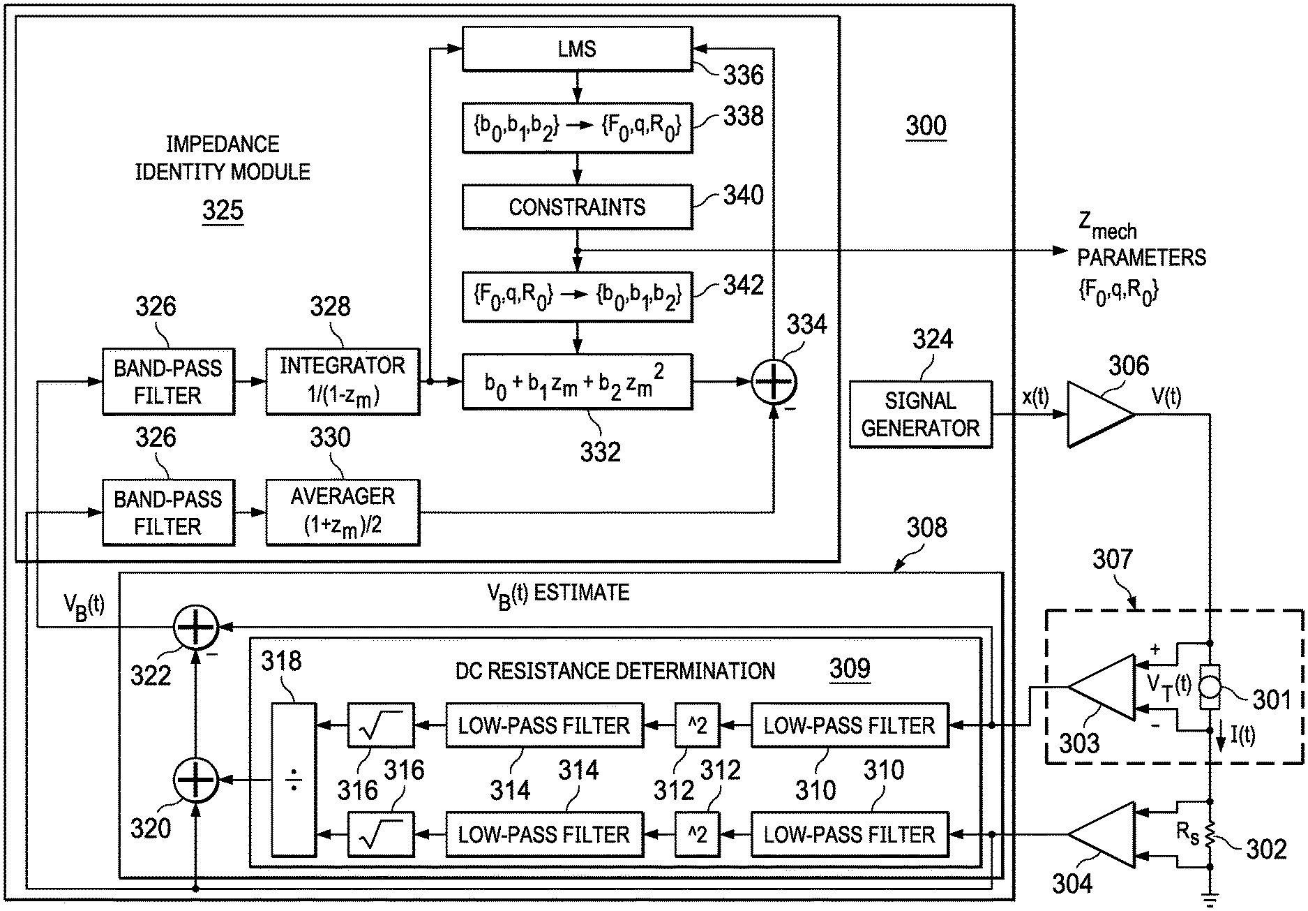
[0031] FIG. 3 illustrates an example system 300 for identifying mechanical impedance of an electromagnetic load, in accordance with embodiments of the present disclosure. In some embodiments, system 300 may be integral to a host device comprising system 300 and haptic transducer 301. Such device may include, without limitation, a mobile device, home application, a vehicle, and/or any other system, device, or apparatus that includes a human-machine interface.
[0032] In operation, a signal generator 324 of system 300 may generate a waveform signal x(t). Waveform signal x(t) may in turn be amplified by amplifier 306 to generate the driving signal V(t) for driving haptic transducer 301. Although FIG. 3 depicts haptic transducer 301, in some embodiments, another electromagnetic load (e.g., a loudspeaker, a microspeaker, a piezoelectric transducer) may be present in lieu of haptic transducer 301.
[0033] Responsive to driving signal V(t), a sensed terminal voltage V.sub.T(t) of haptic transducer 301 may be converted to a digital representation by a first analog-to-digital converter (ADC) 303. Similarly, sensed current I(t) may be converted to a digital representation by a second ADC 304. Current I(t) may be sensed across a shunt resistor 302 having resistance R.sub.s coupled to a terminal of haptic transducer 301. The terminal voltage V.sub.T(t) may be sensed by a terminal voltage sensing block 307, for example a volt meter.
[0034] As shown in FIG. 3, system 300 may include a back-EMF estimate block 308 that may estimate back-EMF voltage V.sub.B(t). In general, back EMF voltage V.sub.B(t) may not be directly measured from outside of the haptic transducer. However, the terminal voltage V.sub.T(t) measured at the terminals of the haptic transducer may be related to V.sub.B(t) by:
V T ( t ) = V B ( t ) + Re I ( t ) + Le dI ( t ) dt ( 7 ) ##EQU00003##
where the parameters are defined as described with reference to FIG. 2. Consequently, back-EMF voltage V.sub.B(t) may be estimated according to equation (7) which may be rearranged as:
V B ( t ) = V T ( t ) - Re I ( t ) - Le dI ( t ) dt ( 8 ) ##EQU00004##
[0035] In some embodiments, back-EMF estimate block 308 may be implemented as a digital filter with a proportional and parallel difference path. The estimates of DC resistance Re and inductance Le may not need to be accurate (e.g., within an approximate 10% error may be acceptable), and thus, fixed values from an offline calibration or from a data sheet specification may be sufficient.
[0036] For example, a DC resistance determination block 309 may provide an estimate of the DC resistance Re and inductance Le, determined as a ratio (e.g., using divider 318) of the root-mean-square sensed terminal voltage V.sub.T(t) (using a squaring block 312 and a square root block 316) to the root-mean-square sensed current I(t) (using a squaring block 312 and a square root block 316) at frequencies below resonant frequency f.sub.0, using one or more low-pass filters (e.g., filters 310 and 314) to filter out higher frequencies. Second filters 314 may be present to reduce alternating current (AC) components to avoid division by zero in calculations of DC resistance determination block 309. Accordingly, back-EMF voltage V.sub.B(t) may be estimated by calculating a voltage drop across a coil of haptic transducer 301 (e.g., calculated by multiplier 320) and subtracting such voltage drop from terminal voltage V.sub.T(t) (e.g., with combiner 322).
[0037] As shown in FIG. 3, system 300 may include an impedance identity module 325 configured to apply a least-mean-squares (LMS) adaptive filter (e.g., a three-tap finite impulse response filter 332 controlled by an LMS adaptive algorithm 336) to back-EMF voltage V.sub.B(t) and sensed current I(t) to determine the parameters (angular resonant frequency .omega..sub.0, quality factor q, and resistance at resonance R.sub.ES) of mechanical impedance Z.sub.mech. Impedance identity module 325 may include band-pass filters 326 each configured to band-pass filter each of estimated back-EMF voltage V.sub.B(t) and sensed current I(t) around resonant frequency f.sub.0.
[0038] A fixed integrator filter 328
( e . g . , with response 1 1 - z m ) ##EQU00005##
may filter the band-pass filtered estimated back-EMF voltage V.sub.B(t), which may serve as an input to an adaptive LMS algorithm 336. A fixed averaging filter 330
( e . g . , a moving average filter with response 1 + z m 2 ) ##EQU00006##
may filter the band-pass filtered sensed current I(t), which may serve as a target to the adaptive LMS algorithm.
[0039] A three-tap adaptive finite impulse response filter 332 (e.g., with response b.sub.0+b.sub.1z.sub.m+b.sub.2z.sub.m.sup.2) having coefficients b.sub.0, b.sub.1, and b.sub.2 controlled by adaptive LMS algorithm 336 may filter the result of integrator 328. Combiner 334 may subtract the result of fixed averaging filter 330 from finite impulse response filter 332 to generate an error signal used to derive filter coefficient update by LMS algorithm 336.
[0040] LMS algorithm 336 may perform any suitable least-mean-squares approach to minimize the error signal generated by combiner 334, including without limitation a normalized LMS algorithm or a recursive least squares algorithm. In some embodiments, LMS algorithm 336 may normalize the update to help with filter convergence and thus may implement a normalized LMS algorithm.
[0041] A mapping block 338 may map filter coefficients {b.sub.0, b.sub.1, b.sub.2} into parameters {.omega..sub.0, q, R.sub.ES} of mechanical impedance Z.sub.mech. To illustrate such mapping, it is noted that when a current I.sub.load(t) passes through the mechanical impedance, the voltage across that mechanical impedance, the back-EMF voltage V.sub.B(t), may be given as V.sub.B(t)=Z.sub.mechI.sub.load(t). Using equation (4) above, such equation for back-EMF voltage V.sub.B(t) may be rewritten as:
I load = V B 1 s q .omega. 0 R 0 ( 1 + 1 q .omega. 0 s + 1 q .omega. 0 s 2 ) ( 9 ) ##EQU00007##
[0042] The continuous time system of Equation (9) may be mapped to an equivalent discrete-time system in which integrator response 1/s is mapped to the integrator 328 with response
1 1 - z m ##EQU00008##
and the second-degree polynomial
q .omega. 0 R 0 ( 1 + 1 q .omega. 0 s + 1 q .omega. 0 s 2 ) ##EQU00009##
is mapped to the polynomial
( b 0 + b 1 z m + b 2 z m 2 ) 2 1 + z m . ##EQU00010##
Thus, mapping block 338 can use bilinear transformation to map coefficients {b.sub.0, b.sub.1, b.sub.2} to parameters {.omega..sub.0, q, R.sub.ES} of mechanical impedance Z.sub.mech.
[0043] The foregoing explanation also demonstrates the various inputs to LMS algorithm 336, as using the mapping on Equation (9) and rewriting Equation (9) may result in:
2 1 + z m I load = ( b 0 + b 1 z m + b 2 z m 2 ) 1 1 - z m V B ( 10 ) ##EQU00011##
[0044] Thus, as demonstrated in Equation (10), impedance identity module 324 may input the integrated back-EMF voltage
1 1 - z m V B ##EQU00012##
into adaptive filter 332, generate a two-cycle averaged load current
2 1 + z m I load ##EQU00013##
as the target of adaptive filter 332, and adaptive filter 332 defined by coefficients {b.sub.0, b.sub.1, b.sub.2} may be adapted by LMS algorithm 336 to model parameters {.omega..sub.0, q, R.sub.ES} of mechanical impedance Z.sub.mech.
[0045] A constraints block 340 may constrain parameters {.omega..sub.0, q, R.sub.ES} of mechanical impedance Z.sub.mech within expected bounds to provide system 300's estimates of such parameters, which may in turn be estimated plant parameters for system 300. Another mapping block 342 may map constrained parameters {.omega..sub.0, q, R.sub.ES} of mechanical impedance Z.sub.mech into filter coefficients {b.sub.0, b.sub.1, b.sub.2} for adaptive filter 332.
[0046] Accordingly, using system 300, total impedance of haptic transducer 301 may be modeled in discrete time as a third order infinite impulse response filter with a current input and voltage output. To prepare system 300 for LMS adaption, the model of the plant for the impedance may be split into two parts: (a) one that models the DC impedance (e.g., by DC resistance determination block 309) and (b) one that models mechanical admittance (e.g., by impedance identity module 325). Such LMS formulation of mechanical impedance may result in a low-cost approach for determining mechanical impedance, and may also yield a continuous update which may provide convenience in tracking changing load parameters.
[0047] While the foregoing contemplates the calculation of particular parameters of mechanical impedance Z.sub.mech, namely resonant frequency f.sub.0, quality factor q, and resistance at resonance R.sub.ES, it is understood that systems and methods similar to that disclosed herein may be used to identify one or more other parameters for mechanical impedance Z.sub.mech.
[0048] As used herein, when two or more elements are referred to as "coupled" to one another, such term indicates that such two or more elements are in electronic communication or mechanical communication, as applicable, whether connected indirectly or directly, with or without intervening elements.
[0049] This disclosure encompasses all changes, substitutions, variations, alterations, and modifications to the example embodiments herein that a person having ordinary skill in the art would comprehend. Similarly, where appropriate, the appended claims encompass all changes, substitutions, variations, alterations, and modifications to the example embodiments herein that a person having ordinary skill in the art would comprehend. Moreover, reference in the appended claims to an apparatus or system or a component of an apparatus or system being adapted to, arranged to, capable of, configured to, enabled to, operable to, or operative to perform a particular function encompasses that apparatus, system, or component, whether or not it or that particular function is activated, turned on, or unlocked, as long as that apparatus, system, or component is so adapted, arranged, capable, configured, enabled, operable, or operative. Accordingly, modifications, additions, or omissions may be made to the systems, apparatuses, and methods described herein without departing from the scope of the disclosure. For example, the components of the systems and apparatuses may be integrated or separated. Moreover, the operations of the systems and apparatuses disclosed herein may be performed by more, fewer, or other components and the methods described may include more, fewer, or other steps. Additionally, steps may be performed in any suitable order. As used in this document, "each" refers to each member of a set or each member of a subset of a set.
[0050] Although exemplary embodiments are illustrated in the figures and described below, the principles of the present disclosure may be implemented using any number of techniques, whether currently known or not. The present disclosure should in no way be limited to the exemplary implementations and techniques illustrated in the drawings and described above.
[0051] Unless otherwise specifically noted, articles depicted in the drawings are not necessarily drawn to scale.
[0052] All examples and conditional language recited herein are intended for pedagogical objects to aid the reader in understanding the disclosure and the concepts contributed by the inventor to furthering the art, and are construed as being without limitation to such specifically recited examples and conditions. Although embodiments of the present disclosure have been described in detail, it should be understood that various changes, substitutions, and alterations could be made hereto without departing from the spirit and scope of the disclosure.
[0053] Although specific advantages have been enumerated above, various embodiments may include some, none, or all of the enumerated advantages. Additionally, other technical advantages may become readily apparent to one of ordinary skill in the art after review of the foregoing figures and description.
[0054] To aid the Patent Office and any readers of any patent issued on this application in interpreting the claims appended hereto, applicants wish to note that they do not intend any of the appended claims or claim elements to invoke 35 U.S.C. .sctn. 112(f) unless the words "means for" or "step for" are explicitly used in the particular claim.
* * * * *
D00000
D00001
D00002


XML
uspto.report is an independent third-party trademark research tool that is not affiliated, endorsed, or sponsored by the United States Patent and Trademark Office (USPTO) or any other governmental organization. The information provided by uspto.report is based on publicly available data at the time of writing and is intended for informational purposes only.
While we strive to provide accurate and up-to-date information, we do not guarantee the accuracy, completeness, reliability, or suitability of the information displayed on this site. The use of this site is at your own risk. Any reliance you place on such information is therefore strictly at your own risk.
All official trademark data, including owner information, should be verified by visiting the official USPTO website at www.uspto.gov. This site is not intended to replace professional legal advice and should not be used as a substitute for consulting with a legal professional who is knowledgeable about trademark law.