Power Battery Pack Safety Prevention And Control System For Electric Vehicle And Control Method
FENG; XU-NING ; et al.
U.S. patent application number 16/900992 was filed with the patent office on 2020-10-01 for power battery pack safety prevention and control system for electric vehicle and control method. This patent application is currently assigned to Tsinghua University. The applicant listed for this patent is Tsinghua University. Invention is credited to XU-NING FENG, XIANG-MING HE, LAN-GUANG LU, MING-GAO OUYANG, YUE PAN, LI WANG.
| Application Number | 20200313245 16/900992 |
| Document ID | / |
| Family ID | 1000004901329 |
| Filed Date | 2020-10-01 |
| United States Patent Application | 20200313245 |
| Kind Code | A1 |
| FENG; XU-NING ; et al. | October 1, 2020 |
POWER BATTERY PACK SAFETY PREVENTION AND CONTROL SYSTEM FOR ELECTRIC VEHICLE AND CONTROL METHOD
Abstract
Disclosed are a power battery pack safety prevention and control system for an electric vehicle and a control method. The power battery pack safety prevention and control system includes a signal collection device, a master controller, and a stepwise prevention and control actuator. The master controller includes a fault diagnosis device, a cell thermal runway determination device, and a battery pack thermal runway spread determination device which are respectively electrically connected to the stepwise prevention and control actuator and send different control instructions to the stepwise prevention and control actuator. The stepwise prevention and control actuator can perform different levels of prevention and control actions according to different control instructions sent by the fault diagnosis device, the cell thermal runway determination device, and the battery pack thermal runway spread determination device. The power battery pack safety prevention and control system for an electric vehicle can provide an active prevention and control measure and a passive prevention and control measure, accurately activate a prevention and control mechanism according to an actual situation of an accident in combination with the prevention and control capability of the prevention and control system, maximize the effect of the safety protection, and ensure the safety of the passenger in the electric vehicle.
| Inventors: | FENG; XU-NING; (Beijing, CN) ; HE; XIANG-MING; (Beijing, CN) ; WANG; LI; (Beijing, CN) ; OUYANG; MING-GAO; (Beijing, CN) ; LU; LAN-GUANG; (Beijing, CN) ; PAN; YUE; (Beijing, CN) | ||||||||||
| Applicant: |
|
||||||||||
|---|---|---|---|---|---|---|---|---|---|---|---|
| Assignee: | Tsinghua University Beijing CN |
||||||||||
| Family ID: | 1000004901329 | ||||||||||
| Appl. No.: | 16/900992 | ||||||||||
| Filed: | June 15, 2020 |
Related U.S. Patent Documents
| Application Number | Filing Date | Patent Number | ||
|---|---|---|---|---|
| PCT/CN2018/114168 | Nov 6, 2018 | |||
| 16900992 | ||||
| Current U.S. Class: | 1/1 |
| Current CPC Class: | H01M 2200/10 20130101; H01M 10/63 20150401; H01M 10/4257 20130101; H01M 10/486 20130101; H01M 10/625 20150401; H01M 2220/20 20130101; H01M 10/6567 20150401; H01M 10/6556 20150401; H01M 2010/4271 20130101 |
| International Class: | H01M 10/42 20060101 H01M010/42; H01M 10/48 20060101 H01M010/48; H01M 10/625 20060101 H01M010/625; H01M 10/63 20060101 H01M010/63; H01M 10/6556 20060101 H01M010/6556; H01M 10/6567 20060101 H01M010/6567 |
Foreign Application Data
| Date | Code | Application Number |
|---|---|---|
| Dec 18, 2017 | CN | 201711366401.9 |
Claims
1. A power battery pack safety prevention and control system for an electric vehicle, comprising a battery pack for powering the electric vehicle, a signal collection device, a master controller, and a stepwise prevention and control actuator; wherein one end of the signal collection device is electrically connected to the battery pack, and another end of the signal collection device is electrically connected to the master controller, the signal collection device is configured to acquire monitoring information of the battery pack and transmit the monitoring information to the master controller; the master controller comprises a fault diagnosis device, a cell thermal runaway determination device and a battery pack thermal runaway spread determination device; the fault diagnosis device, the cell thermal runaway determination device and the battery pack thermal runaway spread determination device are electrically connected to the stepwise prevention and control actuator respectively, and are respectively configured to send a control instruction to the stepwise prevention and control actuator; the stepwise prevention and control actuator is configured to perform a prevention and control action according to control instructions sent by the fault diagnosis device, the cell thermal runaway determination device, and the battery pack thermal runaway spread determination device.
2. The power battery pack safety prevention and control system for an electric vehicle according to claim 1, wherein the fault diagnosis device comprises an internal short-circuit detector, an external short-circuit detector, a charge-discharge fault detector, an insulation failure detector, a collision detector, a liquid leakage and fire detector, and an overheat detector; the internal short-circuit detector, the external short-circuit detector, the charge-discharge fault detector, the insulation failure detector, the collision detector, the liquid leakage and fire detector and the overheat detector are electrically connected to the signal collection device respectively; the internal short-circuit detector, the external short-circuit detector, the charge-discharge fault detector, the insulation failure detector, the collision detector, the liquid leakage and fire detector and the overheat detector are respectively configured to perform a parallel fault diagnosis on different types of faults, determine a fault type and send a control instruction for a fault of a fault level one to the stepwise prevention and control actuator according to different fault types.
3. The power battery pack safety prevention and control system for an electric vehicle according to claim 2, wherein the internal short-circuit detector comprises a processor, a selector, an electrochemical status determination device, a thermogenesis status determination device and a logic-arithmetic unit; one end of the electrochemical status determination device and one end of the thermogenesis status determination device are respectively connected to the battery pack; the other end of the electrochemical status determination device and the other end of the thermogenesis status determination device are respectively connected to the processor; the electrochemical status determination device is configured to acquire information of the battery pack having an extreme electrochemical status, perform a model-based electrochemical abnormal status detection, and output a detection result of an electrochemical status of the battery pack; the thermogenesis status determination device is configured to acquire information of the battery pack having an extreme thermogenesis status, perform a model-based thermogenesis abnormal status detection, and output a detection result of a thermogenesis status of the battery pack; the processor is configured to store position and status information of the battery pack, the processor is further configured to generate a control instruction of a prevention and control action; the selector is configured to screen an extreme battery pack based on an average+difference model; the logic-arithmetic unit is configured to perform a logical operation according to a detection results obtained by the electrochemical status determination device and the thermogenesis status determination device, and output an operation result to the processor.
4. The power battery pack safety prevention and control system for an electric vehicle according to claim 1, wherein the cell thermal runaway determination device comprises a battery cell thermal runaway predictor and a battery cell thermal runaway locator respectively electrically connected to the signal collection device; the battery cell thermal runaway predictor is configured to predict a possibility of an occurrence of battery cell thermal runaway, the battery cell thermal runaway locator is configured to determine a zone in which the battery cell thermal runaway occurs; the battery cell thermal runaway predictor and the battery cell thermal runaway locator are respectively configured to send a control instruction for a fault of a fault level two to the stepwise prevention and control actuator according to different possibilities of the occurrence of the battery cell thermal runaway and different zones in which the battery cell thermal runaway occurs.
5. The power battery pack safety prevention and control system for an electric vehicle according to claim 1, wherein the battery pack thermal runaway spread determination device comprises a battery pack thermal runaway spread predictor and a battery pack thermal runaway spread locator respectively electrically connected to the signal collection device; the battery pack thermal runaway spread predictor is configured to determine whether thermal runaway spread occurs in the battery pack and an adjacent zone, the battery pack thermal runaway spread locator is configured to locate a zone in which the battery pack thermal runaway spread occurs; the battery pack thermal runaway spread predictor and the battery pack thermal runaway spread locator are respectively configured to send a control instruction for a fault of a fault level three to the stepwise prevention and control actuator according to different conditions comprising whether the thermal runaway spread occurs in the battery pack, the zone in which the battery pack thermal runaway spread occurs, whether a thermal runaway spread-induced fire occurs in the battery pack, and whether a battery cell catches fire.
6. The power battery pack safety prevention and control system for an electric vehicle according to claim 1, wherein the battery pack thermal runaway spread determination device further comprises a battery pack thermal runaway spread-induced fire determination device, a battery pack thermal runaway spread-induced explosion determination device and a timer; the battery pack thermal runaway spread-induced fire determination device, the battery pack thermal runaway spread-induced explosion determination device and the timer are electrically connected to the signal collection device respectively; the battery pack thermal runaway spread-induced fire determination device is configured to determine whether a thermal runaway spread-induced fire occurs in the battery pack; the battery pack thermal runaway spread-induced explosion determination device is configured to determine whether a thermal runaway spread-induced explosion occurs in the battery pack, and send a control instruction for a fault of a fault level four to the stepwise prevention and control actuator if an explosion occurs; the timer is electrically connected to the battery pack thermal runaway spread-induced explosion determination device, and is configured to record a time interval from the battery cell thermal runaway to the explosion of the battery pack.
7. The power battery pack safety prevention and control system for an electric vehicle according to claim 1, wherein the stepwise prevention and control actuator comprises an alarm device, a thermal runaway inducement suppression device, a thermal runaway zone suppression device, a fire extinguishing device and a safety relief device respectively electrically connected to the master controller; the thermal runaway inducement suppression device comprises a shutoff device and an isolating device; the shutoff device and the isolating device are respectively provided to perform a corresponding prevention and control action, the shutoff device is configured to shut off a fault cell and a fault zone circuit, the isolating device is configured to isolate the fault cell, isolate a charge-discharge circuit, and shut off a main circuit of the battery pack.
8. The power battery pack safety prevention and control system for an electric vehicle according to claim 7, wherein the thermal runaway spread suppression system comprises a heat flow passive guide device and a heat flow active guide device, a heat exchanger and a combustible gas extraction device; the heat flow passive guide device is provided in a different zone of the battery pack and is configured to passively guide flow of heat when thermal runaway occurs; the heat flow active guide device is provided in a different zone of the battery pack and is configured to actively guiding flow of heat when thermal runaway occurs; the heat exchanger is provided in a different zone of the battery pack and is configured to complete heat exchange between the battery pack and an outside world; the combustible gas extraction device is provided in a different zone of the battery pack and is configured to complete outward discharge of a combustible gas.
9. The power battery pack safety prevention and control system for an electric vehicle according to claim 8, wherein the fire extinguishing device comprises a fire extinguishing agent tank body, a fire extinguishing agent delivery pipeline and a fire extinguishing agent injection valve body; the fire extinguishing agent tank body is connected to the fire extinguishing agent injection valve body through the fire extinguishing agent delivery pipeline; the fire extinguishing agent injection valve body comprises a fire extinguishing agent injection valve body in a first zone I and a fire extinguishing agent injection valve body in a second zone II, the fire extinguishing agent injection valve body in the first zone I and the fire extinguishing agent injection valve body in the second zone II are configured to complete spraying of different doses of extinguishing agent.
10. The power battery pack safety prevention and control system for an electric vehicle according to claim 1, wherein the master controller is in communication with the stepwise prevention and control actuator through a network.
11. A control method for a power battery pack safety prevention and control system for an electric vehicle, wherein the power battery pack safety prevention and control system comprises: a battery pack for powering an electric vehicle; a signal collection device, one end of which is electrically connected to the battery pack; a master controller, electrically connected to the other end of the signal collection device; and a stepwise prevention and control actuator, electrically connected to the master controller; the control method comprises following steps: S100: acquiring, by the signal collection device, monitoring information of the battery pack, and transmitting the monitoring information to the master controller; S200: generating, by the master controller, a control instruction according to the monitoring information, and sending the control instruction to the stepwise prevention and control actuator; S300: performing, by the stepwise prevention and control actuator, a prevention and control action according to the control instruction sent by the master controller.
12. The control method for the power battery pack safety prevention and control system for the electric vehicle according to claim 11, wherein the master controller comprises a fault diagnosis device, a cell thermal runaway determination device and a battery pack thermal runaway spread determination device, the fault diagnosis device, the cell thermal runaway determination device and the battery pack thermal runaway spread determination device are respectively electrically connected to the stepwise prevention and control actuator; the step S200 further comprises: S210: generating, by one or more of the fault diagnosis device, the cell thermal runaway determination device and the battery pack thermal runaway spread determination device, at least one control instruction according to the monitoring information, and sending the at least one control instruction to the stepwise prevention and control actuator.
13. The control method for the power battery pack safety prevention and control system for the electric vehicle according to claim 12, wherein the fault diagnosis device comprises an internal short-circuit detector, an external short-circuit detector, a charge-discharge fault detector, an insulation failure detector, a collision detector, a liquid leakage and fire detector and an overheat detector; the internal short-circuit detector, the external short-circuit detector, the charge-discharge fault detector, the insulation failure detector, the collision detector, the liquid leakage and fire detector and the overheat detector are respectively electrically connected to the signal collection device; the step S210 further comprises: S211: respectively performing, by the internal short-circuit detector, the external short-circuit detector, the charge-discharge fault detector, the insulation failure detector, the collision detector, the liquid leakage and fire detector and the overheat detector, a parallel fault diagnosis on different types of faults, determining a fault type, and respectively sending a control instruction for a fault of a fault level one to the stepwise prevention and control actuator according to different fault types.
14. The control method for the power battery pack safety prevention and control system for the electric vehicle according to claim 12, wherein the internal short-circuit detector comprises a processor, a selector, an electrochemical status determination device, a thermogenesis status determination device and a logic-arithmetic unit; one end of the electrochemical status determination device and one end of the thermogenesis status determination device are respectively connected to the battery pack, the other end of the electrochemical status determination device and the other end of the thermogenesis status determination device are respectively connected to the processor; the control method further comprises: acquiring, by the electrochemical status determination device, information of the battery pack having an extreme electrochemical status, performing a model-based electrochemical abnormal status detection, and outputting a detection result of an electrochemical status of the battery pack; acquiring, by the thermogenesis status determination device, information of the battery pack having an extreme thermogenesis status, performing a model-based thermogenesis abnormal status detection, and outputting a detection result of a thermogenesis status of the battery pack; storing, by the processor, location and status information of the battery pack, and generating a control instruction of a prevention and control action; screening, by the selector, an extreme battery pack based on an "average+difference" model; performing, by the logic-arithmetic unit, a logical operation according to detection results obtained by the electrochemical status determination device and the thermogenesis status determination device, and outputting an operation result to the processor.
15. The control method for the power battery pack safety prevention and control system for the electric vehicle according to claim 12, wherein the cell thermal runaway determination device comprises a battery cell thermal runaway predictor and a battery cell thermal runaway locator respectively electrically connected to the signal collection device; the step S210 further comprises: S212: predicting, by the battery cell thermal runaway predictor, a possibility of an occurrence of battery cell thermal runaway; determining, by the battery cell thermal runaway locator, a zone in which the battery cell thermal runaway occurs; S213: sending, by the battery cell thermal runaway predictor and the battery cell thermal runaway locator respectively, a control instruction for a fault of a fault level two to the stepwise prevention and control actuator according to different possibilities of occurrences of the battery cell thermal runaway and different zones in which the battery cell thermal runaway occurs.
16. The control method for the power battery pack safety prevention and control system for the electric vehicle according to claim 12, wherein the battery pack thermal runaway spread determination device comprises a battery pack thermal runaway spread predictor and a battery pack thermal runaway spread locator respectively electrically connected to the signal collection device; the step S210 further comprises: S214: determining, by the battery pack thermal runaway spread predictor, whether thermal runaway spread occurs in the battery pack and an adjacent zone; locating, by the battery pack thermal runaway spread locator, a zone in which the battery pack thermal runaway spread occurs; S215: sending, by the battery pack thermal runaway spread predictor and the battery pack thermal runaway spread locator respectively, a control instruction for a fault of a fault level three to the stepwise prevention and control actuator according to different conditions comprising whether thermal runaway spread occurs in the battery pack, a zone in which the battery pack thermal runaway spread occurs, whether a thermal runaway spread-induced fire occurs in the battery pack, and whether a battery cell catches fire.
17. The control method for the power battery pack safety prevention and control system for the electric vehicle according to claim 12, wherein the battery pack thermal runaway spread determination device further comprises a battery pack thermal runaway spread-induced fire determination device, a battery pack thermal runaway spread-induced explosion determination device and a timer; the battery pack thermal runaway spread-induced fire determination device, the battery pack thermal runaway spread-induced explosion determination device, and the timer are electrically connected to the signal collection device respectively, and the timer is electrically connected to the battery pack thermal runaway spread-induced explosion determination device; the step S210 further comprises: S216: determining, by the battery pack thermal runaway spread-induced fire determination device, whether a thermal runaway spread-induced fire occurs in the battery pack; S217: determining, by the battery pack thermal runaway spread-induced explosion determiner, whether a thermal runaway spread-induced explosion occurs in the battery pack, and sending a control instruction for a fault of a fault level four to the stepwise prevention and control actuator if an explosion occurs; S218: recording, by the timer, a time interval from the battery cell thermal runaway to the explosion of the battery pack.
18. The control method for the power battery pack safety prevention and control system for the electric vehicle according to claim 11, wherein the stepwise prevention and control actuator comprises an alarm device, a thermal runaway inducement suppression device, a thermal runaway zone suppression device, a fire extinguishing device and a safety relief device respectively electrically connected to the master controller; the thermal runaway inducement suppression device comprises a shutoff device and an isolating device, the shutoff device and the isolating device are respectively provided to perform a corresponding prevention and control action; the thermal runaway spread suppression system comprises a heat flow passive guide device, a heat flow active guide device, a heat exchanger, and a combustible gas extraction device; the heat flow passive guide device is provided in a different zone of the battery pack, the heat flow active guide device is provided in a different zone of the battery pack, the heat exchanger is provided in a different zone of the battery pack, the combustible gas extraction device is provided in a different zone of the battery pack; the control method further comprises one or more of following steps: shutting off, by the shutoff device, a fault cell and a fault zone circuit; isolating, by the isolating device, the fault cell and a charge-discharge circuit, and shutting off a main circuit of the battery pack; passively guiding, by the heat flow passive guide device, flow of heat; actively guiding, by the heat flow active guide device, flow of heat; implementing, by the heat exchanger, heat exchange between the battery pack and an outside world; implementing, by the combustible gas extraction device, outward discharge of a combustible gas.
19. The control method for the power battery pack safety prevention and control system for the electric vehicle according to claim 18, wherein the fire extinguishing device comprises a fire extinguishing agent tank body, a fire extinguishing agent delivery pipeline, and a fire extinguishing agent injection valve body; the fire extinguishing agent tank body is connected to the fire extinguishing agent injection valve body through the fire extinguishing agent delivery pipeline; the fire extinguishing agent injection valve body comprises a fire extinguishing agent injection valve body in a first zone I and a fire extinguishing agent injection valve body in a second zone II; the control method further comprises: spraying, by the fire extinguishing agent injection valve body in the first zone I and the fire extinguishing agent injection valve body in the second zone II, different doses of fire extinguishing agent.
20. A power battery pack safety prevention and control system for an electric vehicle, comprising a battery pack, a signal collection device, a master controller, and a stepwise prevention and control actuator; wherein the battery pack is configured to power the electric vehicle; one end of the signal collection device is electrically connected to the battery pack, and the other end of the signal collection device is connected to the master controller, the signal collection device is configured to acquire monitoring information of the battery pack and transmit the monitoring information to the master controller; the master controller comprises a fault diagnosis device, a cell thermal runaway determination device, and a battery pack thermal runaway spread determination device; the fault diagnosis device, the cell thermal runaway determination device and the battery pack thermal runaway spread determination device are electrically connected to the stepwise prevention and control actuator respectively, and are respectively configured to send a control instruction to the stepwise prevention and control actuator; the stepwise prevention and control actuator is configured to perform a prevention and control action according to control instructions sent by the fault diagnosis device, the cell thermal runaway determination device and the battery pack thermal runaway spread determination device; wherein the fault diagnosis device comprises an internal short-circuit detector, an external short-circuit detector, a charge-discharge fault detector, an insulation failure detector, a collision detector, a liquid leakage and fire detector and an overheat detector; the internal short-circuit detector, the external short-circuit detector, the charge-discharge fault detector, the insulation failure detector, the collision detector, the liquid leakage and fire detector and the overheat detector are respectively electrically connected to the signal collection device; the internal short-circuit detector, the external short-circuit detector, the charge-discharge fault detector, the insulation failure detector, the collision detector, the liquid leakage and fire detector and the overheat detector are respectively configured to perform a parallel fault diagnosis on different types of faults, determine a fault type, and send a control instruction for a fault of a fault level one to the stepwise prevention and control actuator according to different fault types; wherein, the battery pack thermal runaway spread determination device further comprises a battery pack thermal runaway spread-induced fire determination, a battery pack thermal runaway spread-induced explosion determination device, and a timer; the battery pack thermal runaway spread-induced fire determination device, the battery pack thermal runaway spread-induced explosion determination device and the timer are respectively electrically connected to the signal collection device; the battery pack thermal runaway spread-induced fire determination device is configured to determine whether a thermal runaway spread-induced fire occurs in the battery pack; the battery pack thermal runaway spread-induced explosion determination device is configured to determine whether a thermal runaway spread-induced explosion occurs in the battery pack, and send a control instruction for a fault of a fault level four to the stepwise prevention and control actuator if an explosion occurs; the timer is electrically connected to the battery pack thermal runaway spread-induced explosion determination device, and is configured to record a time interval from battery cell thermal runaway to the explosion of the battery pack; wherein, the stepwise prevention and control actuator comprises an alarm device, a thermal runaway inducement suppression device, a thermal runaway zone suppression device, a fire extinguishing device and a safety relief device respectively electrically connected to the master controller; the thermal runaway inducement suppression device comprises a shutoff device and an isolating device; the shutoff device and the isolating device are respectively provided to perform a corresponding prevention and control action, the shutoff device is configured to shut off a fault cell and a fault zone circuit, and the isolating device is configured to isolate the fault cell, isolate a charge-discharge circuit, and shut off a main circuit of the battery pack.
Description
CROSS REFERENCE TO RELATED APPLICATION
[0001] This application is a continuation application of International Application PCT/CN2018/114168, entitled "Power Battery Pack Safety Prevention and Control System for Electric Vehicle and Control Method", filed on Nov. 6, 2018, which claims priority to China Patent Application No. 201711366401.9, entitled "Power Battery Pack Safety Prevention and Control System for Electric Vehicle," filed on Dec. 18, 2017, the contents of which are expressly incorporated herein by reference in their entirety.
TECHNICAL FIELD
[0002] The present disclosure relates to the fields of electric vehicle and battery techniques, and particularly to a power battery pack safety prevention and control system for an electric vehicle and a control method.
BACKGROUND
[0003] Electric vehicles are new energy vehicles, and power batteries are a core energy source of the electric vehicles. The power batteries are generally assembled to meet the driving needs of the electric vehicles. A power battery pack for a vehicle should be provided with a safety prevention and control system to ensure the safety of the power battery pack for the vehicle in use.
[0004] In general, the safety accidents of electric vehicles are characterized by multiple stages. In the first stage, a battery system fails, and the fault may induce thermal runaway of a battery cell. In the second stage, the thermal runaway of the battery cells in the battery system occurs, which may cause a local fire. In the third stage, the thermal runaway spread occurs in the battery system, with the possibility of spreading the fire. For the above three stages, the safety prevention and control system provided on the power battery pack for the vehicle should have corresponding prevention and control measures.
[0005] In the conventional battery monitoring and management system and monitoring method for an electric vehicle, the thermal runaway of the battery is determined by voltages, temperatures, smog concentrations, and gas concentrations collected in real time. The monitoring system and monitoring method can only be used for alarming when thermal runaway occurs. No active and direct prevention and control scheme is proposed for the thermal runaway problem of the battery, and no warning scheme for early fault caused by the thermal runaway is proposed. The monitoring system and method cannot effectively suppress the spread of thermal runaway in the battery pack after thermal runaway of the battery cell occurs, and the actual effect of safety prevention and control is limited. It can be seen from the above that most conventional solutions are passive prevention and control measures provided for the second and third stages of the safety accidents of the electric vehicle. The conventional technical solutions cannot actively and directly monitor the fault of the battery system of the electric vehicle, and cannot comprehensively improve the safety of the battery pack of the electric vehicle.
SUMMARY
[0006] A power battery pack safety prevention and control system for an electric vehicle is provided, which includes a battery pack for powering the electric vehicle, and further includes a signal collection device, a master controller and a stepwise prevention and control actuator;
[0007] one end of the signal collection device is electrically connected to the battery pack, and the other end of the signal collection device is electrically connected to the master controller, the signal collection device is configured to acquire monitoring information of the battery pack and transmit the monitoring information to the master controller;
[0008] the master controller includes a fault diagnosis device, a cell thermal runaway determination device and a battery pack thermal runaway spread determination device; the fault diagnosis device, the cell thermal runaway determination device and the battery pack thermal runaway spread determination device are electrically connected to the stepwise prevention and control actuator respectively, and are respectively configured to send a control instruction to the stepwise prevention and control actuator;
[0009] the stepwise prevention and control actuator is configured to perform a prevention and control action according to control instructions sent by the fault diagnosis device, the cell thermal runaway determination device, and the battery pack thermal runaway spread determination device.
[0010] A control method for a power battery pack safety prevention and control system for an electric vehicle is provided. The power battery pack safety prevention and control system includes:
[0011] a battery pack for powering an electric vehicle;
[0012] a signal collection device, one end of which is electrically connected to the battery pack;
[0013] a master controller, electrically connected to the other end of the signal collection device; and
[0014] a stepwise prevention and control actuator, electrically connected to the master controller;
[0015] the control method includes the following steps:
[0016] S100: acquiring, by the signal collection device, monitoring information of the battery pack, and transmitting the monitoring information to the master controller;
[0017] S200: generating, by the master controller, a control instruction according to the monitoring information, and sending the control instruction to the stepwise prevention and control actuator;
[0018] S300: performing, by the stepwise prevention and control actuator, a prevention and control action according to the control instruction sent by the master controller.
[0019] A power battery pack safety prevention and control system for an electric vehicle is provided, which includes a battery pack, a signal collection device, a master controller, and a stepwise prevention and control actuator;
[0020] the battery pack is configured to power the electric vehicle;
[0021] one end of the signal collection device is electrically connected to the battery pack, and the other end of the signal collection device is connected to the master controller, the signal collection device is configured to acquire monitoring information of the battery pack and transmit the monitoring information to the master controller;
[0022] the master controller comprises a fault diagnosis device, a cell thermal runaway determination device, and a battery pack thermal runaway spread determination device; the fault diagnosis device, the cell thermal runaway determination device and the battery pack thermal runaway spread determination device are electrically connected to the stepwise prevention and control actuator respectively, and are respectively configured to send a control instruction to the stepwise prevention and control actuator;
[0023] the stepwise prevention and control actuator is configured to perform a prevention and control action according to control instructions sent by the fault diagnosis device, the cell thermal runaway determination device and the battery pack thermal runaway spread determination device;
[0024] the fault diagnosis device comprises an internal short-circuit detector, an external short-circuit detector, a charge-discharge fault detector, an insulation failure detector, a collision detector, a liquid leakage and fire detector and an overheat detector;
[0025] the internal short-circuit detector, the external short-circuit detector, the charge-discharge fault detector, the insulation failure detector, the collision detector, the liquid leakage and fire detector and the overheat detector are respectively electrically connected to the signal collection device;
[0026] the internal short-circuit detector, the external short-circuit detector, the charge-discharge fault detector, the insulation failure detector, the collision detector, the liquid leakage and fire detector and the overheat detector are respectively configured to perform a parallel fault diagnosis on different types of faults, determine a fault type, and send a control instruction for a fault of a fault level one to the stepwise prevention and control actuator according to different fault types;
[0027] the battery pack thermal runaway spread determination device further comprises a battery pack thermal runaway spread-induced fire determination, a battery pack thermal runaway spread-induced explosion determination device, and a timer;
[0028] the battery pack thermal runaway spread-induced fire determination device, the battery pack thermal runaway spread-induced explosion determination device and the timer are respectively electrically connected to the signal collection device;
[0029] the battery pack thermal runaway spread-induced fire determination device is configured to determine whether a thermal runaway spread-induced fire occurs in the battery pack;
[0030] the battery pack thermal runaway spread-induced explosion determination device is configured to determine whether a thermal runaway spread-induced explosion occurs in the battery pack, and send a control instruction for a fault of a fault level four to the stepwise prevention and control actuator if an explosion occurs;
[0031] the timer is electrically connected to the battery pack thermal runaway spread-induced explosion determination device, and is configured to record a time interval from battery cell thermal runaway to the explosion of the battery pack;
[0032] the stepwise prevention and control actuator comprises an alarm device, a thermal runaway inducement suppression device, a thermal runaway zone suppression device, a fire extinguishing device and a safety relief device respectively electrically connected to the master controller;
[0033] the thermal runaway inducement suppression device comprises a shutoff device and an isolating device, the shutoff device and the isolating device are respectively provided to perform a corresponding prevention and control action, the shutoff device is configured to shut off a fault cell and a fault zone circuit, and the isolating device is configured to isolate the fault cell, isolate a charge-discharge circuit, and shut off a main circuit of the battery pack.
[0034] The present disclosure provides a power battery pack safety prevention and control system for an electric vehicle and a control method. The power battery pack safety prevention and control system for an electric vehicle includes a signal collection device, a master controller and a stepwise prevention and control actuator, and is capable of providing active prevention and control measures and passive prevention and control measures. The master controller includes a fault diagnosis device, a cell thermal runaway determination device, and a battery pack thermal runaway spread determination device which are respectively electrically connected to the stepwise prevention and control actuator and send different control instructions to the stepwise prevention and control actuator. The stepwise prevention and control actuator can perform different levels of prevention and control actions according to different control instructions sent by the fault diagnosis device, the cell thermal runaway determination device and the battery pack thermal runaway spread determination device. The power battery pack safety prevention and control system for an electric vehicle and the control method can accurately activate the prevention and control mechanism according to the actual situation of the accident in combination with the prevention and control capability of the prevention and control system, maximize the effect of the safety protection and ensure the safety of the passenger in the electric vehicle. The power battery pack safety prevention and control system for an electric vehicle and the control method of the present disclosure can also make the active prevention and control measures and passive prevention and control measures complement each other, reinforce each other, and jointly solve the technical problem of the safety prevention and control of the battery pack of the electric vehicle.
BRIEF DESCRIPTION OF DRAWINGS
[0035] In order to describe the embodiments of the present disclosure or the technical solutions in the prior art more clearly, accompanying drawings required for descriptions of the embodiments or the prior art will be briefly introduced below. Apparently, the accompanying drawings in the following descriptions are merely several exemplary embodiments of the present disclosure. Those skilled in the art can obtain other drawings according to the disclosed accompanying drawings without any creative work.
[0036] FIG. 1 is a schematic structure diagram illustrating a power battery pack safety prevention and control system for an electric vehicle according to an embodiment;
[0037] FIG. 2 is a partial schematic structure diagram of a power battery pack safety prevention and control system for an electric vehicle according to an embodiment;
[0038] FIG. 3 is a partial schematic structure diagram of a power battery pack safety prevention and control system for an electric vehicle according to an embodiment;
[0039] FIG. 4 is a schematic zone diagram of a battery pack according to an embodiment;
[0040] FIG. 5 is a schematic structure diagram illustrating a battery pack of a power battery pack safety prevention and control system for an electric vehicle according to an embodiment;
[0041] FIG. 6 is a schematic structure diagram illustrating a signal collection device according to an embodiment;
[0042] FIG. 7 is a schematic diagram illustrating a hardware structure of a master controller according to an embodiment;
[0043] FIG. 8 is a schematic structure diagram illustrating a battery cell thermal runaway determination device according to an embodiment;
[0044] FIG. 9 is a schematic structure diagram illustrating a battery pack thermal runaway spread determination device according to an embodiment;
[0045] FIG. 10 is a schematic structure diagram illustrating an internal short-circuit detector according to an embodiment;
[0046] FIG. 11 is a communication structure diagram of a master controller and a stepwise prevention and control actuator according to an embodiment;
[0047] FIG. 12 is a schematic structure diagram illustrating a stepwise prevention and control actuator according to an embodiment;
[0048] FIG. 13 is a schematic diagram illustrating a signal connection between a signal collection device and a master controller according to an embodiment;
[0049] FIG. 14 shows a determination of a fault category of a power battery pack safety prevention and control system for an electric vehicle, and a corresponding fault measure according to an embodiment; and
[0050] FIG. 15 is a control logic diagram of a power battery pack safety prevention and control system for an electric vehicle according to an embodiment.
DETAILED DESCRIPTION OF DISCLOSED EMBODIMENTS
[0051] The technical solutions of the embodiments of the present disclosure will be described clearly and completely in combination with the accompanying drawings in the embodiments of the present disclosure. Apparently, the described embodiments are merely part of embodiments of the present disclosure, rather than all embodiments. Based on the embodiments of the present disclosure, all other embodiments obtained by a person of ordinary skill in the art without creative work fall within the scope of protection of the present disclosure.
[0052] Safety accidents of a power battery pack safety prevention and control system for an electric vehicle are characterized by multiple stages. In the first stage, a battery system fails, and the fault forms an inducement of thermal runaway of a battery cell. In the second stage, thermal runaway of the battery cell in the battery system occurs, which may cause a local fire. In the third stage, the thermal runaway spread occurs in the battery system, with the possibility of the fire spread.
[0053] As for the first stage, when a fault occurs, a timely warning should be raised. Especially in a situation where the warning is not fully stipulated in relevant test standards, it is necessary to establish a real-time early-warning mechanism for long-term safety supervision of a full life cycle, such as a fault diagnosis of a self-induced internal short circuit, a real-time diagnosis of liquid leakage of a battery cell, and an early warning mechanism thereof.
[0054] As for the second stage, in addition to the timely alarming when the thermal runaway occurs, the prevention and control system should also initiate a thermal runaway spread suppression measure to delay or even prevent the occurrence of the thermal runaway spread. If a fire occurs during the thermal runaway of the battery cell, the prevention and control system should extinguish the fire in time to prevent further damage to a battery pack element caused by flame burning.
[0055] As for the third stage, when thermal runaway spread occurs, the prevention and control system should have an ability to prevent and control accidents again, and can do its best to delay and prevent occurrence of an explosion event that may cause great harm to personnel. For a situation of a possible second fire, the prevention and control system should have an ability to extinguish the second fire.
[0056] In safety accidents of the electric vehicle, fire and explosion of the battery pack are the most worrying phenomena. It is necessary to have clear understanding of possible fire and explosion phenomena of the battery pack, and formulate reasonable prevention and control functions. As for three elements of fire, i.e., a high temperature, a combustible and oxygen, the prevention and control system is generally designed for these three elements. As for the high temperature condition, when a battery pack has a safety accident, a local high temperature condition is mainly caused by the thermal runaway. Accordingly, in order to prevent and control a battery pack fire, it is very important to weaken the high temperature condition caused by the thermal runaway. If a timely warning can be raised in a fault stage (i.e., the first stage) before the thermal runaway occurs, the thermal runaway does not occur, that is, the occurrence of fire is fundamentally prevented. Of course, a mode of increasing a cooling capacity by a cooling system after the thermal runaway occurs, and a mode of spraying the extinguishing agent by a fire extinguishing device to reduce the temperature after the fire, are also effective. As for the combustible, it is currently believed that the most combustible combustibles are an organic electrolyte inside a lithium-ion power battery when the battery pack has a safety accident. The organic electrolyte leaks and diffuses inside the battery pack, which may cause fire spread or even explosion. If an organic electrolyte leakage occurs, it is feasible prevention and control measures to exhaust the combustible gas in time such that no zone inside the battery system reaches a limit of the fire or explosion. As for the oxygen, a concentration of the oxygen can be diluted through a mode of spraying the extinguishing agent by the fire extinguishing device, or an effect of the oxygen can be removed through a mode of filling the battery pack with inert gas. However, when a lithium-ion power battery has the thermal runaway, a certain amount of active oxygen may be generated inside the lithium-ion power battery itself, the mode of filling the battery pack with the inert gas to suppress the fire of the battery pack may have a limited effect.
[0057] It should be noted that although fire and explosion protection control is an important part of the battery pack safety prevention and control, only carrying out the fire and explosion protection control during the battery safety prevention and control cannot guarantee the safety of the battery pack to the greatest extent. Because the thermal runaway of the battery is the common key issue of the safety of the battery pack, and the thermal runaway is not a sufficient condition for the fire and explosion. The battery pack safety prevention and control should take the thermal runaway prevention and control as a core, and the stepwise prevention and control is performed on the accident phenomena sequentially occurred such as the fault inducement, the battery cell thermal runaway, the thermal runaway spread, the fire and explosion, etc. In addition, the gas released when the thermal runaway of the battery pack occurs may cause a suffocation risk of a passenger, which also requires attention during the process of the stepwise safety prevention and control.
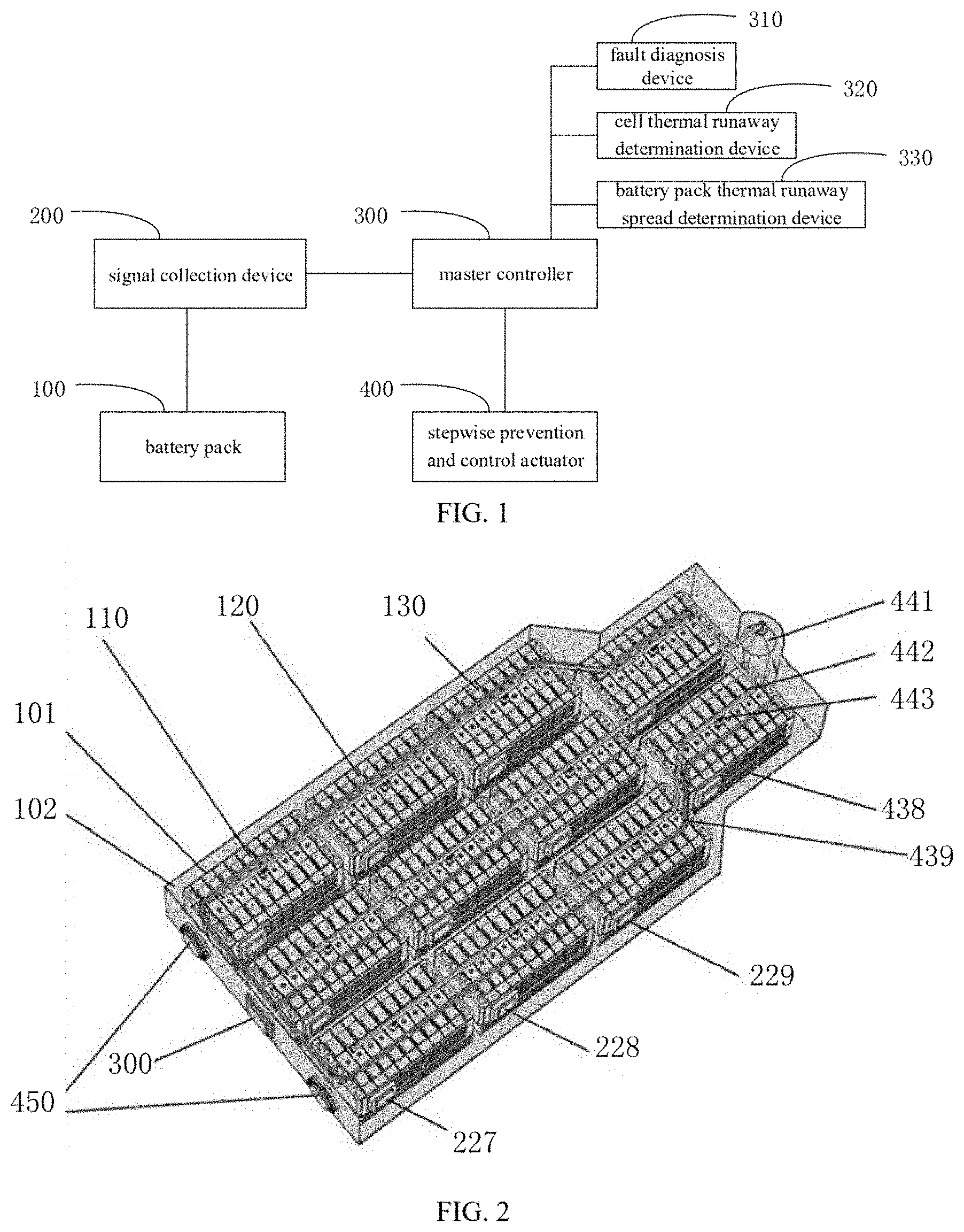
[0058] Referring to FIG. 1, a power battery pack safety prevention and control system 10 for an electric vehicle, includes a battery pack 100, a signal collection device 200, a master controller 300 and a stepwise prevention and control actuator 400. As shown in FIG. 1, one end of the signal collection device 200 is electrically connected to the battery pack 100, and the other end of the signal collection device 200 is electrically connected to the master controller 300. The signal collection device 200 is configured to acquire monitoring information of the battery pack 100 and transmit the monitoring information to the master controller 300. The master controller 300 is electrically connected to the stepwise prevention and control actuator 400, and is configured to complete transmission of a control signal to the stepwise prevention and control actuator 400.
[0059] In the present embodiment, the master controller 300 of the power battery pack safety prevention and control system 10 for the electric vehicle can send different control instructions to control the stepwise prevention and control actuator 400 to perform different levels of prevention and control actions. The power battery pack safety prevention and control system 10 for the electric vehicle can accurately start the prevention and control mechanism in combination with the prevention and control capability of the prevention and control system according to an actual situation of a specific accident, maximize the safety protection effect and ensure the safety of passengers in the electric vehicle. The power battery pack safety prevention and control system 10 for the electric vehicle can also make the active prevention and control measures and the passive prevention and control measures complement each other, reinforce each other, and jointly solve the problem of the safety prevention and control of the power battery pack for the electric vehicle. The active prevention and control measures refer to real-time monitoring of characteristics of the battery system accidents and timely warning according to the above-mentioned three stages of the battery safety accidents of the electric vehicle. The passive prevention and control measures refer to adding a corresponding element and a mechanism in a design process as for the characteristics of the battery system accidents according to the three stages of the battery safety accidents of the electric vehicle, to delay or prevent the occurrence or spread of the accidents. The power battery pack safety prevention and control system 10 for the electric vehicle can be combined with the fault diagnosis device 310, the battery cell thermal runaway determination device 320 and the battery pack thermal runaway spread determination device 330 in the master controller 300, to implement that the active prevention and control measures and passive prevention and control measures complement each other and reinforce each other to jointly solve the problem of safety prevention and control of the battery pack of the electric vehicle. The power battery pack safety prevention and control system 10 for the electric vehicle can implement the stepwise prevention and control of the battery pack safety problems according to the multi-stage characteristics of the safety accidents of the battery pack of the electric vehicle, such as a thermal runaway-induced fault, battery cell thermal runaway, battery pack thermal runaway spread, battery pack fire explosion, release of a combustible harmful gas and so on.
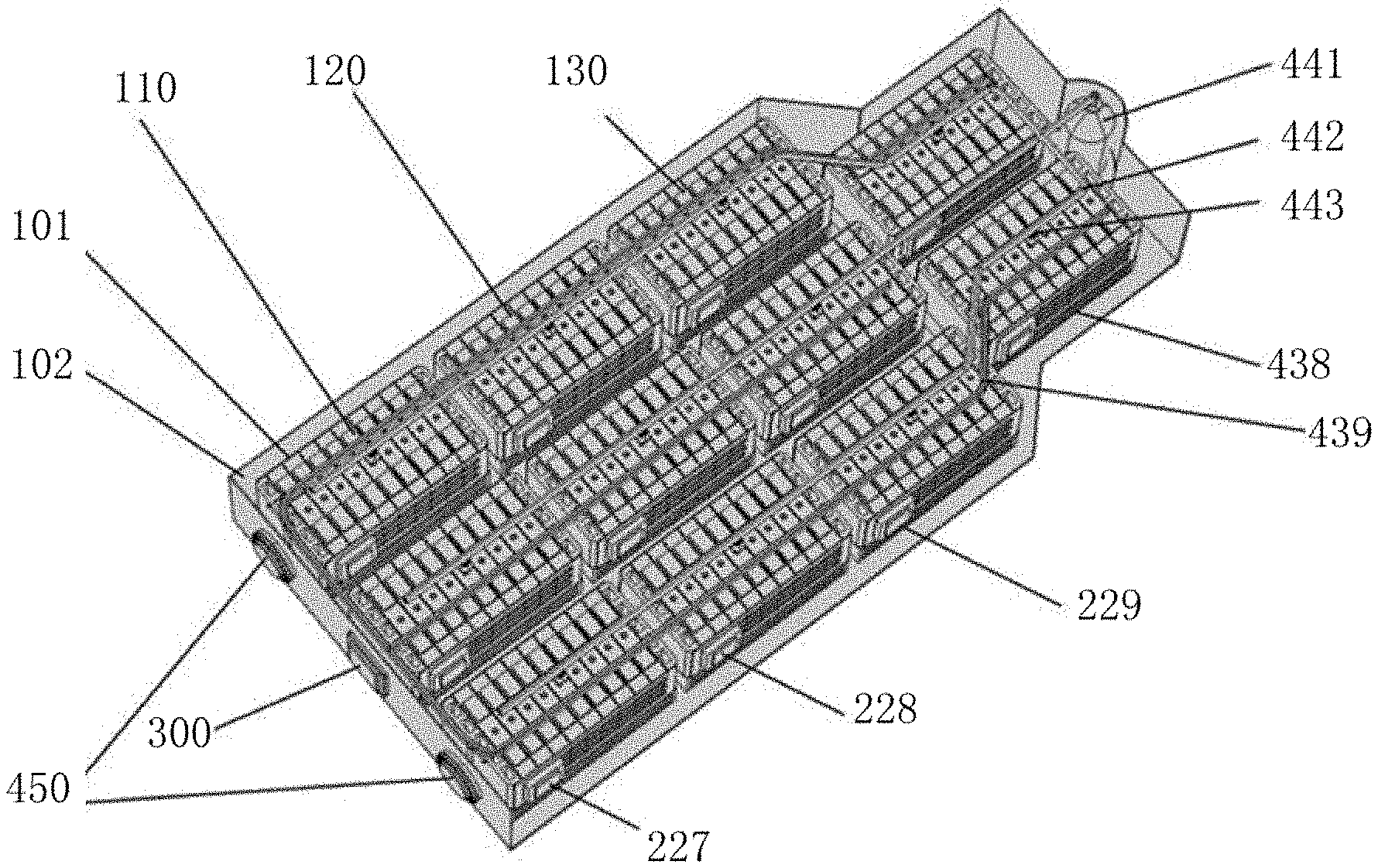
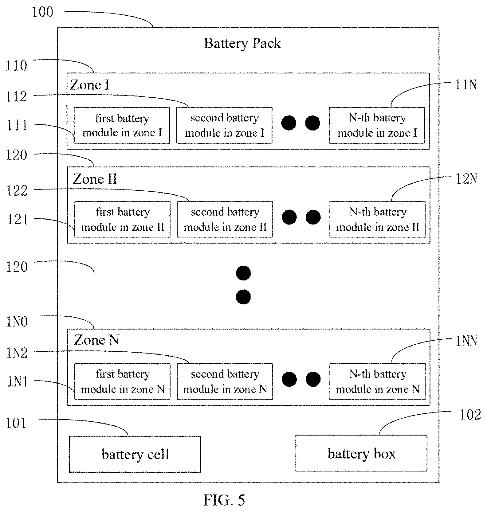
[0060] Referring to FIG. 2 to FIG. 5, specific structure diagrams of the battery pack 100 are provided. The battery pack 100 is configured to power an electric vehicle. The battery pack 100 basically includes a unit battery cell 101. One or more battery cells can form a battery module, and different battery modules can form a battery zone. The battery pack 100 may include a plurality of different zones, for example, a battery pack providing a power and a battery pack providing a signal can be separated. The battery pack 100 may be provided with a battery box 102. A space inside the battery box 102 can include a zone I 110, a zone II 120, a zone III 130, a zone IV 140, a zone V 150, a zone VI 160, a zone VII 170, a zone VIII 180, a zone IX 190, a zone X 1A0, a zone XI 1B0. Different battery modules can be provided in each zone. For example, different battery modules may be provided in the zone I 110. For example: a first battery module 111 in the zone I, a second battery module 112 in the zone I, a third battery module 113 in the zone I, a fourth battery module 114 in the zone I, a fifth battery module 115 in the zone, . . . , an N-th battery module 11N in the zone I. The zone II 120 can be provided with a first battery module 121 in the zone II, a second battery module 122 in the zone II, . . . , an N-th battery module 12N in the zone II, and so on. The battery pack 100 can be provided and reasonably zoned according to different requirements. The specific number of modules in each zone can be set according to the requirement. In order to effectively protect the battery pack 100, the battery pack 100 is zoned according to locations of the battery cells 101. Each zone is provided with one or more sub-modules.
[0061] In an embodiment, the battery pack 100 is divided into eleven zones, and the eleven zones are numbered from 110 to 1B0 as shown in FIG. 4. A and B respectively represent 10 and 11 in hexadecimal. The battery pack 100 includes a battery box 102. A battery cell 101 may be cylindrical, square, or set according to use requirements. A connection mode of each battery module in each zone may be a series connection, a parallel connection, or a series-parallel hybrid connection. The zone design can solve the problem of limited cooling capacity of the thermal runaway spread suppression system due to limited vehicle space and limited amount of fire extinguishing agent carried. In the case of thermal runaway or a fire, the thermal runaway spread can be suppressed and the fire is extinguished at a fixed point in a zone.
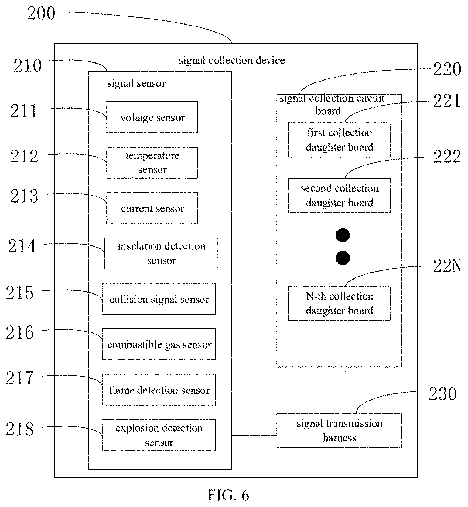
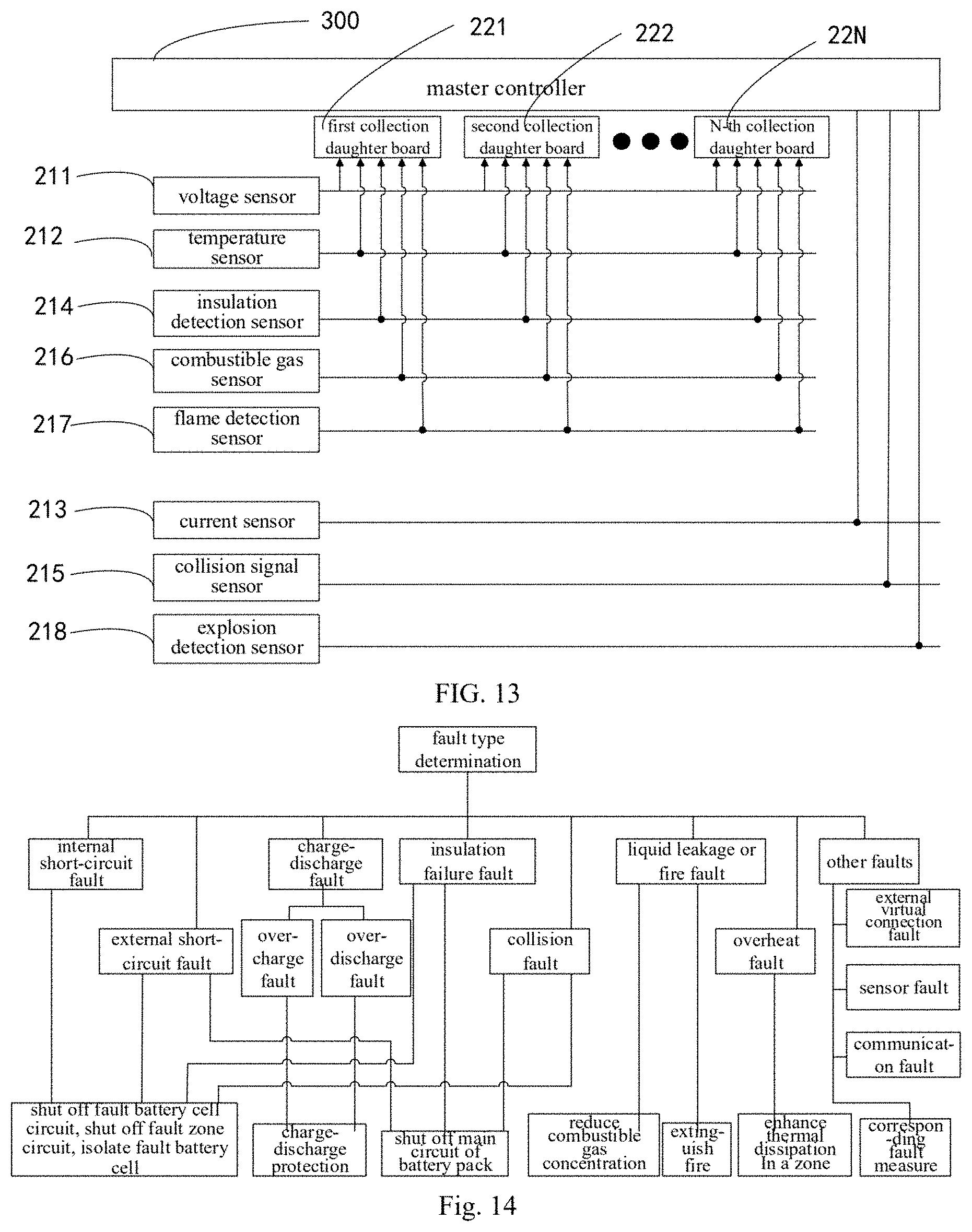
[0062] Referring to FIG. 6, a signal collection device 200 is provided. The signal collection device 200 is mainly configured to detect a battery cell signal, in order to perform an early thermal runaway-induced fault diagnosis. In an embodiment, the signal collection device 200 may include a signal sensor 210, a signal collection circuit board 220, a signal transmission harness 230, etc. The signal sensor 210 is provided at a position adjacent to the battery pack 100, so that current temperature status information and usage status information of the battery pack 100 can be acquired more accurately. The signal collection circuit board 220 is provided in in order to cooperate with the signal sensor 210. There may be multiple signal collection circuit boards 210 provided. Specifically, each signal sensor 210 can be provided with one collection circuit board. For example, the signal collection circuit board 220 includes a first collection daughter board 221, a second collection daughter board 222, . . . , an N-th collection daughter board, and so on. It can be appreciated that the signal collection harness 230 is employed to implement an electric connection and a signal transmission. The signal collection harness 230 can transmit a signal collected by the signal sensor 210 to the controller 300.
[0063] The signal sensor 210 can be one or more of a voltage sensor 211, a temperature sensor 212, a current sensor 213, an insulation detection sensor 214, a collision signal sensor 215, a combustible gas sensor 216, a flame detection sensor 217, and an explosion detection sensor 218. The signal sensor 210 can be provided at different positions of the battery pack 100 according to requirements. Each zone of the battery pack has an independent collection daughter board. A sensor, such as the voltage sensor 211, the temperature sensor 212, the insulation detection sensor 214, the combustible gas sensor 216, or the flame detection sensor 217, transmits a signal to a signal collection daughter board of a corresponding zone, and then the signal is transmitted to the master controller 300 by the signal collection daughter board. The entire battery pack 100 has only one signal sensor. For example, a signal is acquired by the current sensor 213, the collision signal sensor 215, or the explosion detection sensor 218, then the signal is directly transmitted to the master controller 300.
[0064] The specific form of the signal collection device 200 is not limited, and with the development of the technology, there may be other devices capable of detecting the battery pack signal that can be installed in a corresponding position of the battery pack 100. It can be understood that any device that can acquire the battery status information is within the protection scope of the present disclosure. In the present embodiment, multiple detection sensors can acquire the battery status information in all directions, such that the battery status information acquired by the system is more accurate and reliable.
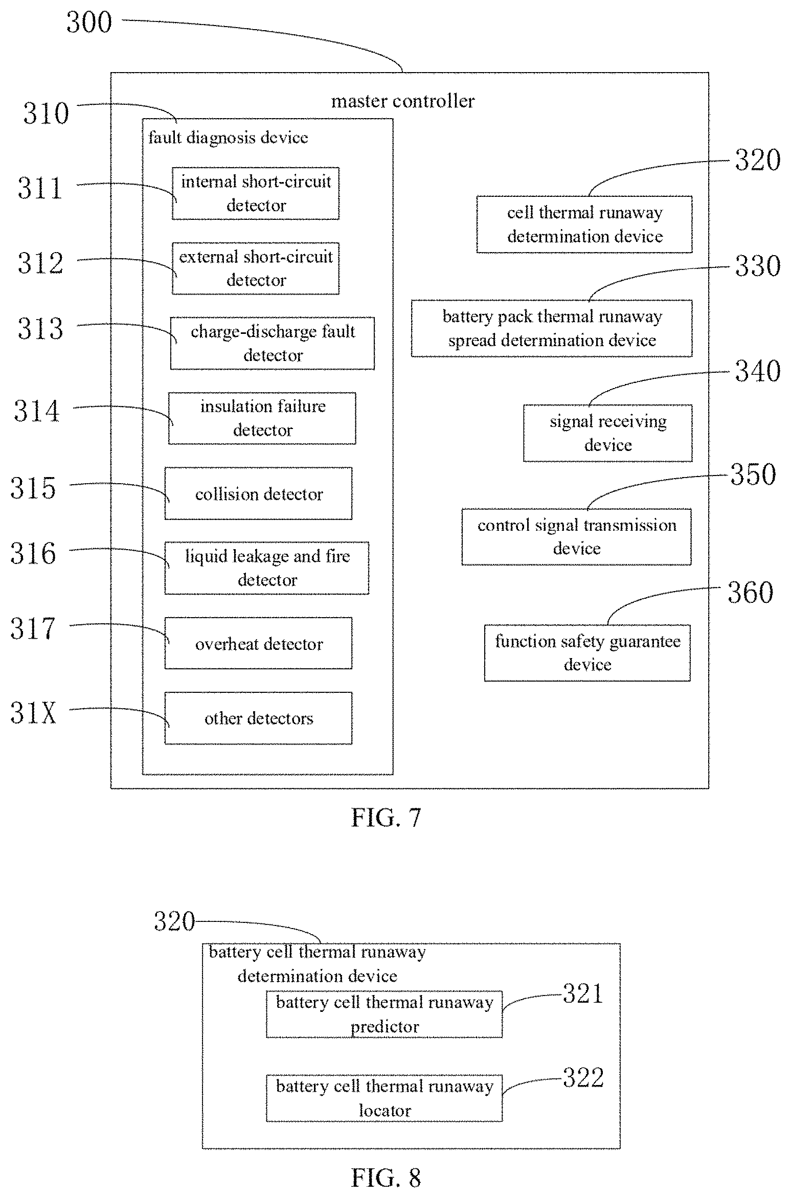
[0065] Referring to FIG. 7, a schematic structure diagram of the master controller 300 is provided. The master controller 300 may include a fault diagnosis device 310, a battery cell thermal runaway determination device 320, and a battery pack thermal runaway spread determination device 330. The fault diagnosis device 310, the battery cell thermal runaway determination device 320, and the battery pack thermal runaway spread determination device 330 are respectively electrically connected to the stepwise prevention and control actuator 400, to send different control instructions to the stepwise prevention and control actuator 400.
[0066] The master controller 300 is mainly configured to monitor the battery safety status based on a model according to a real-time signal of the battery pack 100 detected by the signal collection device 200. The master controller 300 may be provided with a main control chip capable of implementing a corresponding function. The master controller 300 may further include: a signal receiving device 340, a control signal transmission device 350, a function safety guarantee device 360, and the like. A control program for monitoring the battery safety status runs in real time in the master controller chip. The fault diagnosis device 310, the battery cell thermal runaway determination device 320, and the battery pack thermal runaway spread determination device 330 in the master controller 300 complete the real-time monitoring of the battery pack 100 in stages and in functions.
[0067] In an embodiment, the fault diagnosis device 310 includes an internal short-circuit detector 311, an external short-circuit detector 312, a charge-discharge fault detector 313, an insulation failure detector 314, a collision detector 315, a liquid leakage and fire detector 316, an overheat detector 317, and other detectors 31X which are electrically connected to the signal collection device 200 respectively. The above-mentioned different types of fault diagnosis devices 310 can be configured to perform a parallel fault diagnosis on different types of faults and determine a fault type, so as to send a control instruction for a fault of level one to the stepwise prevention and control actuator 400 according to different fault types.
[0068] Referring to FIG. 8, in an embodiment, the battery cell thermal runaway determination device 320 includes a battery cell thermal runaway predictor 321 and a battery cell thermal runaway locator 322. The battery cell thermal runaway predictor 321 and the battery cell thermal runaway locator 322 are respectively electrically connected to the signal collection device 200. The battery cell thermal runaway predictor 321 is configured to predict a possibility of an occurrence of the battery cell thermal runaway. The battery cell thermal runaway locator 322 is configured to determine a zone in which the battery cell thermal runaway occurs. The battery cell thermal runaway locator 322 can send a control instruction for a fault of level two to the stepwise prevention and control actuator 400 according to different possibilities of occurrences of the battery cell thermal runaway and different zones in which the battery cell thermal runaway occurs.
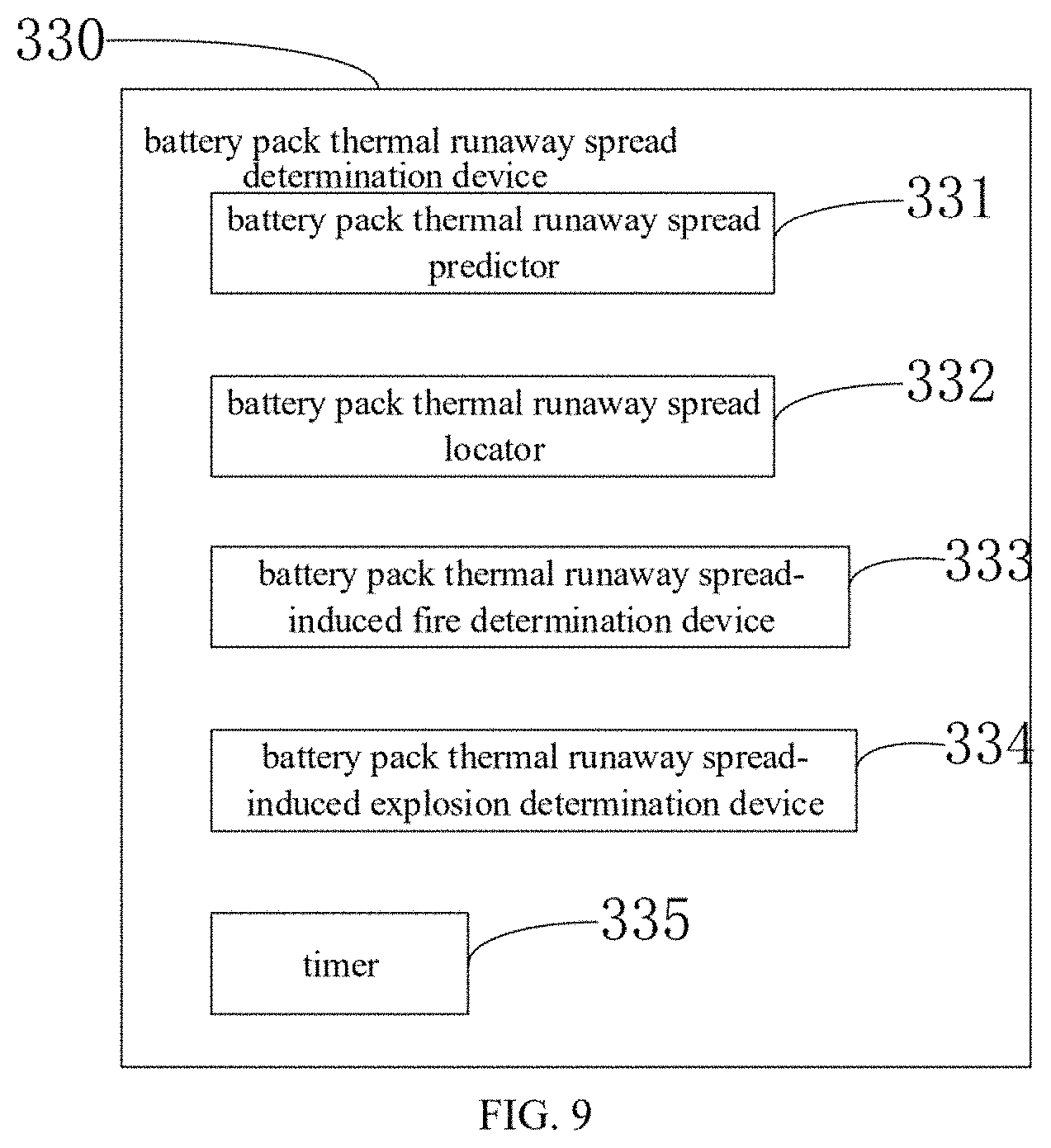
[0069] Referring to FIG. 9, in an embodiment, the battery pack thermal runaway spread determination device 330 includes a battery pack thermal runaway spread predictor 331 and a battery pack thermal runaway spread locator 332. The battery pack thermal runaway spread predictor 331 and the battery pack thermal runaway spread locator 332 are respectively electrically connected to the signal collection device 200. The battery pack thermal runaway spread predictor 331 is configured to determine whether thermal runaway spread occurs in the battery pack and an adjacent zone. The battery pack thermal runaway spread locator 332 is configured to locate a zone in which the battery pack thermal runaway spread occurs. A control instruction for a fault of level three is sent to the stepwise prevention and control actuator 400 according to different conditions such as whether the thermal runaway spread occurs in the battery pack 100, a zone in which the battery pack thermal runaway spread occurs, whether a thermal runaway spread-induced fire occurs in the battery pack, and whether the battery cell catches fire.
[0070] In an embodiment, the battery pack thermal runaway spread determination device 330 further includes: a battery pack thermal runaway spread-induced fire determination device 333, a battery pack thermal runaway spread-induced explosion determination device 334, and a timer 335. The battery pack thermal runaway spread-induced fire determination device 333, the battery pack thermal runaway spread-induced explosion determination device 334, and the timer 335 are electrically connected to the signal collection device 200 respectively. The battery pack thermal runaway spread-induced fire determination device 333 is configured to determine whether a thermal runaway spread-induced fire occurs in the battery pack. The battery pack thermal runaway spread-induced explosion determination device 334 is configured to determine whether a thermal runaway spread-induced explosion occurs in the battery pack. If an explosion occurs, a control instruction for a fault of level four is sent to the stepwise prevention and control actuator 400. The timer 335 is electrically connected to the battery pack thermal runaway spread-induced explosion determination device 334, and is configured to record a time interval from the battery cell thermal runaway to the battery pack explosion.
[0071] The arrangement of the battery pack thermal runaway spread-induced explosion determination device 334 and the timer 335 enables the battery pack thermal runaway spread determination device 330 to obtain a determination result more accurately. When the passive safety design of the battery system is performed, the recorded time interval DTR from the battery cell thermal runaway to the battery pack explosion should ensure that the time interval DTR from battery cell thermal runaway to the battery pack explosion is greater than an escape duration required by a person. In addition, such arrangement is also of great significance for analysis of accidents such as the battery pack thermal runaway spread-induced explosion and so on.
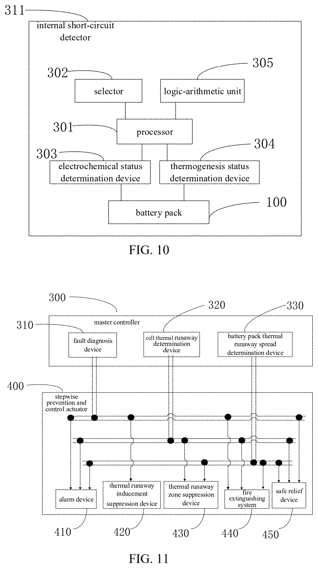
[0072] Referring to FIG. 10, in an embodiment, the internal short-circuit detector 311 includes: a processor 301, a selector 302, an electrochemical status determination device 303, a thermogenesis status determination device 304, and a logic-arithmetic unit 305.
[0073] One end of the electrochemical status determination device 303 and one end of the thermogenesis status determination device 304 are respectively connected to the battery pack 100. The other end of the electrochemical status determination device 303 and the other end of the thermogenesis status determination device 304 are respectively connected to the processor 301. The electrochemical status determination device 303 is configured to acquire information of a battery having an extreme electrochemical status, perform model-based electrochemical abnormal status detection, and output a detection result of an electrochemical status of the battery. The thermogenesis status determination device 304 is configured to acquire information of a battery having an extreme thermogenesis status, perform model-based thermogenesis abnormal status detection, and output a detection result of a thermogenesis status of the battery. The processor 301 is configured to store position and status information of the battery pack 100. The processor 301 is further configured to generate a control instruction of a prevention and control action. The selector 302 is configured to screen an extreme battery based on an "average+difference" model. The logic-arithmetic unit 305 is configured to perform a logical operation based on the detection results obtained by the electrochemical status determination device 303 and the thermogenesis status determination device 304, and output an operation result to the processor 301.
[0074] Specifically, a logic "and" an operation is performed according to the extreme electrochemical status and the extreme thermogenesis status respectively obtained by the electrochemical status determination device 303 and the thermogenesis status determination device 304. If the extreme electrochemical status and the extreme thermogenesis status are both 1, and battery cells corresponding to the extreme electrochemical status and the extreme thermogenesis status are the same battery cell, it is determined that the battery cell has an internal short-circuit fault. The battery cell having the internal short-circuit fault is further estimated to estimate a degree of the internal short circuit, and the prevention and control actuator is required to perform a corresponding prevention and control action, such as alarming, shutting the circuit off, and isolating the internal short-circuit battery, and so on.
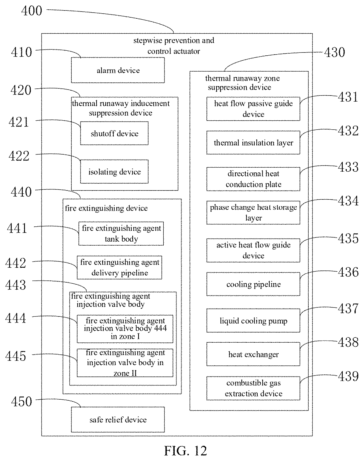
[0075] Referring to FIG. 11, the stepwise prevention and control actuator 400 includes: an alarm device 410, a thermal runaway inducement suppression device 420, a thermal runaway zone suppression device 430, a fire extinguishing device 440, and a safety relief device 450. The alarm device 410, the thermal runaway inducement suppression device 420, the thermal runaway zone suppression device 430, the fire extinguishing device 440, and the safety relief device 450 are electrically connected to the master controller 300 respectively.
[0076] The stepwise prevention and control actuator 400 is configured to perform a prevention and control action of a different level according to a different control instruction sent by the fault diagnosis device 310, the battery cell thermal runaway determination device 320, and the battery pack thermal runaway spread determination device 330. The stepwise prevention and control actuator 400 receives a safety stepwise prevention and control signal in real time sent by the master controller 300, and performs a corresponding safety prevention and control action.
[0077] Also referring to FIG. 11, the master controller 300 is connected to the stepwise prevention and control actuator 400 through a communication network. A corresponding control signal of the fault diagnosis device 310 controls the alarm device 410, the thermal runaway inducement suppression device 420, the fire extinguishing device 440, and the safety relief device 450 to operate. A corresponding control signal of the battery cell thermal runaway determination device 320 controls the alarm device 410, the thermal runaway zone suppression device 430, the fire extinguishing device 440, and the safety relief device 450 to operate. A corresponding control signal of the battery pack thermal runaway spread determination device 330 controls the alarm device 410, the thermal runaway zone suppression device 430, the fire extinguishing device 440, and the safety relief device 450 to operate.
[0078] Referring to FIG. 12, the thermal runaway inducement suppression device 420 includes: a shutoff device 421 and an isolating device 422. The shutoff device 421 and the isolating device 422 are respectively provided as a device to perform a corresponding prevention and control action. The shutoff device 421 is configured to shut off a faulty cell and a fault zone circuit. The isolating device 422 is configured to isolate a fault cell, isolate a charge-discharge circuit, and shut off a main circuit of the battery pack. The thermal runaway inducement suppression device 420 can implement the functions of shutting off a faulty cell, shutting off a fault zone circuit, and isolating a faulty cell. The thermal runaway inducement suppression device 420 can also implement functions of charging and discharging protection, shutting off the main circuit of the battery pack, enhancing thermal dissipation in a corresponding zone, reducing a concentration of the combustible gas, and extinguishing a non-thermal runaway fire.
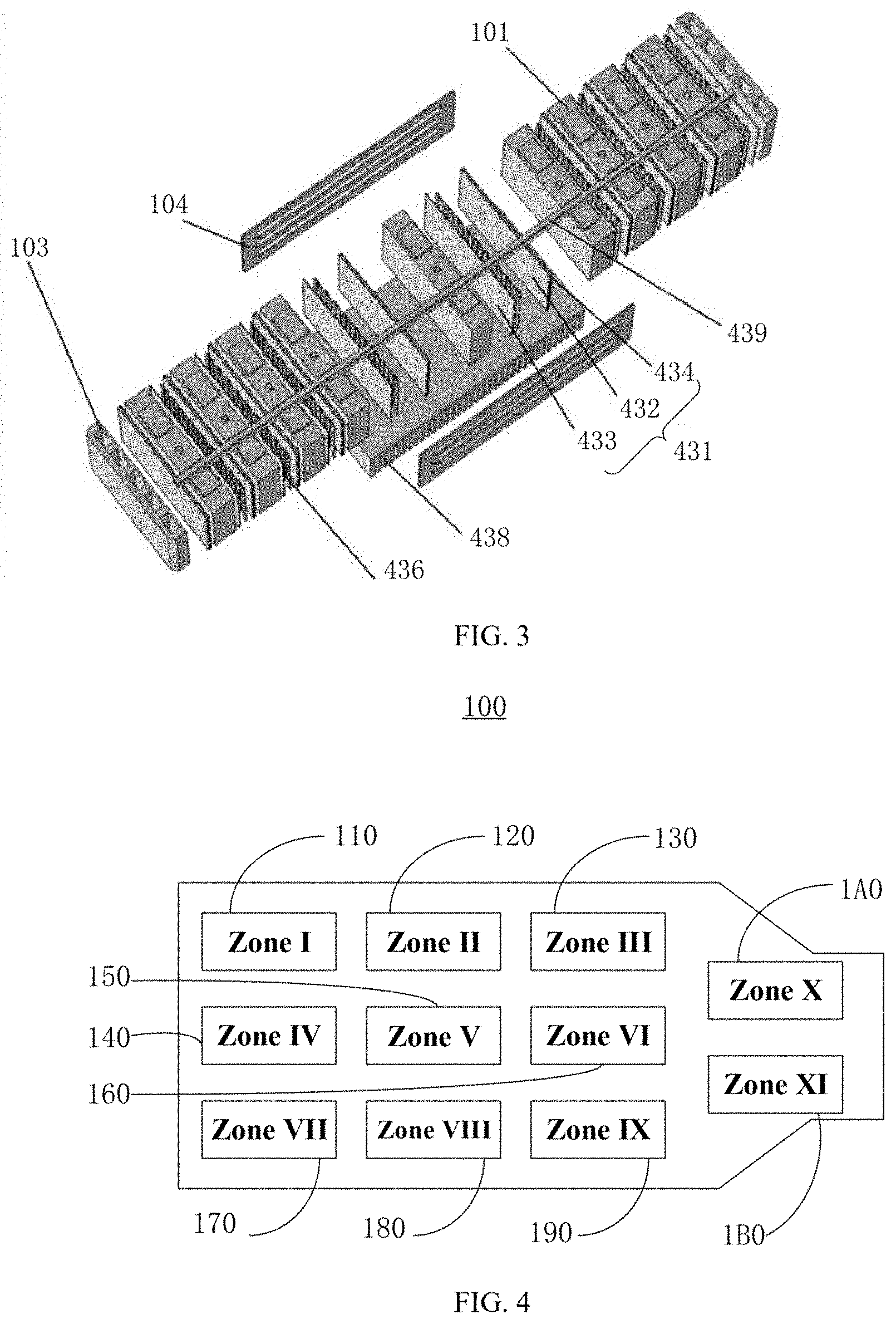
[0079] The thermal runaway spread suppression system 430 includes a heat flow passive guide device 431, a heat flow active guide device 435, a heat exchanger 438, and a combustible gas extraction device 439. In the thermal runaway spread suppression system 430, suppression of the thermal runaway spread is implemented by the heat flow active guide device 435 and the heat flow passive guide device 431. The heat flow active guide device 435, the heat exchanger 438 and the combustible gas extraction device 439 assist each other to implement the active guiding and discharging of the heat flow. The heat flow passive guide device 431, the heat exchanger 438, and the combustible gas extraction device 439 assist each other to implement the passive guiding and discharging of the heat flow. The heat flow passive guide device 431 is provided in different zones of the battery pack 100 and is configured to passively guide the flow of heat when the thermal runaway occurs. The heat flow active guide device 435 is provided in different zones of the battery pack 100 and is configured to actively guide the flow of heat when the thermal runaway occurs. The heat exchanger 438 is provided in different zones of the battery pack 100, and is configured to complete exchange of heat between the battery pack 100 and the outside world. The combustible gas extraction device 439 is provided in different zones of the battery pack 100 and is configured to complete discharging of the combustible gas outward. The heat flow active guide device 435 may include a cooling pipeline 436 and a liquid cooling pump 437. The heat flow passive guide device 431 may include a thermal insulation layer 432, a directional heat conduction plate 433, and a phase change heat storage layer 434.
[0080] In an embodiment, the fire extinguishing device 440 includes a fire extinguishing agent tank body 441, a fire extinguishing agent delivery pipeline 442, and a fire extinguishing agent injection valve body 443. The fire extinguishing agent tank body 441 is connected to the fire extinguishing agent injection valve body 443 through the fire extinguishing agent delivery pipeline 442. The fire extinguishing agent injection valve body 443 includes a fire extinguishing agent injection valve body 444 in a zone I and a fire extinguishing agent injection valve body 445 in a zone II. The fire extinguishing agent injection valve body 444 in the zone I and the fire extinguishing agent injection valve body 445 in the zone II are respectively configured to complete injections of different doses of fire extinguishing agent.
[0081] Referring to FIG. 13, in an embodiment, the master controller 300 is connected to the stepwise prevention and control actuator 400 through a communication network. Specifically, the signal collection device 200 can be connected to the master controller 300 through a communication network. The communication network includes a CAN network, a FlexRay.RTM. network, an RS232 network, a Bluetooth.RTM. or Wi-Fi.RTM. virtual signal transmission network, and so on. The signal collection device 200 is connected to the master controller 300 through a communication network. Each zone of the battery pack has an independent collection daughter board. Each of the voltage sensor 211, the temperature sensor 212, the insulation detection sensor 214, the combustible gas sensor 216 and the flame detection sensor 217 transmits a signal to a respective corresponding daughter board 220 corresponding to a corresponding zone, then the signal is sent to the master controller 300 by the collection daughter board 220. If the entire battery pack 100 has only one signal sensor, such as the current sensor 213, the collision signal sensor 215, the explosion detection sensor 218, etc., the signal is directly sent to the master controller 300.
[0082] Referring to FIG. 14, in an embodiment, whether the battery pack fails can be determined by the fault diagnosis device 310. A fault may include: an internal short-circuit fault, an external short-circuit fault, a charge-discharge fault, an insulation failure fault, a collision fault, a liquid leakage or fire fault, an overheat fault, a virtual connection fault, a communication fault, etc. The fault diagnosis device 310 may include: an internal short-circuit detector 311, an external short-circuit detector 312, a charge-discharge fault detector 313, an insulation failure detector 314, a collision detector 315, a liquid leakage and fire detector 316, an overheat detector 317, other detectors 31X, etc. The above-mentioned sensors are electrically connected to the signal collection device 200 respectively. The above-mentioned detectors are configured to perform parallel fault diagnosis on different types of faults, determine a fault type, and send a control instruction for a fault of level one to the stepwise prevention and control actuator 400 according to different fault types.
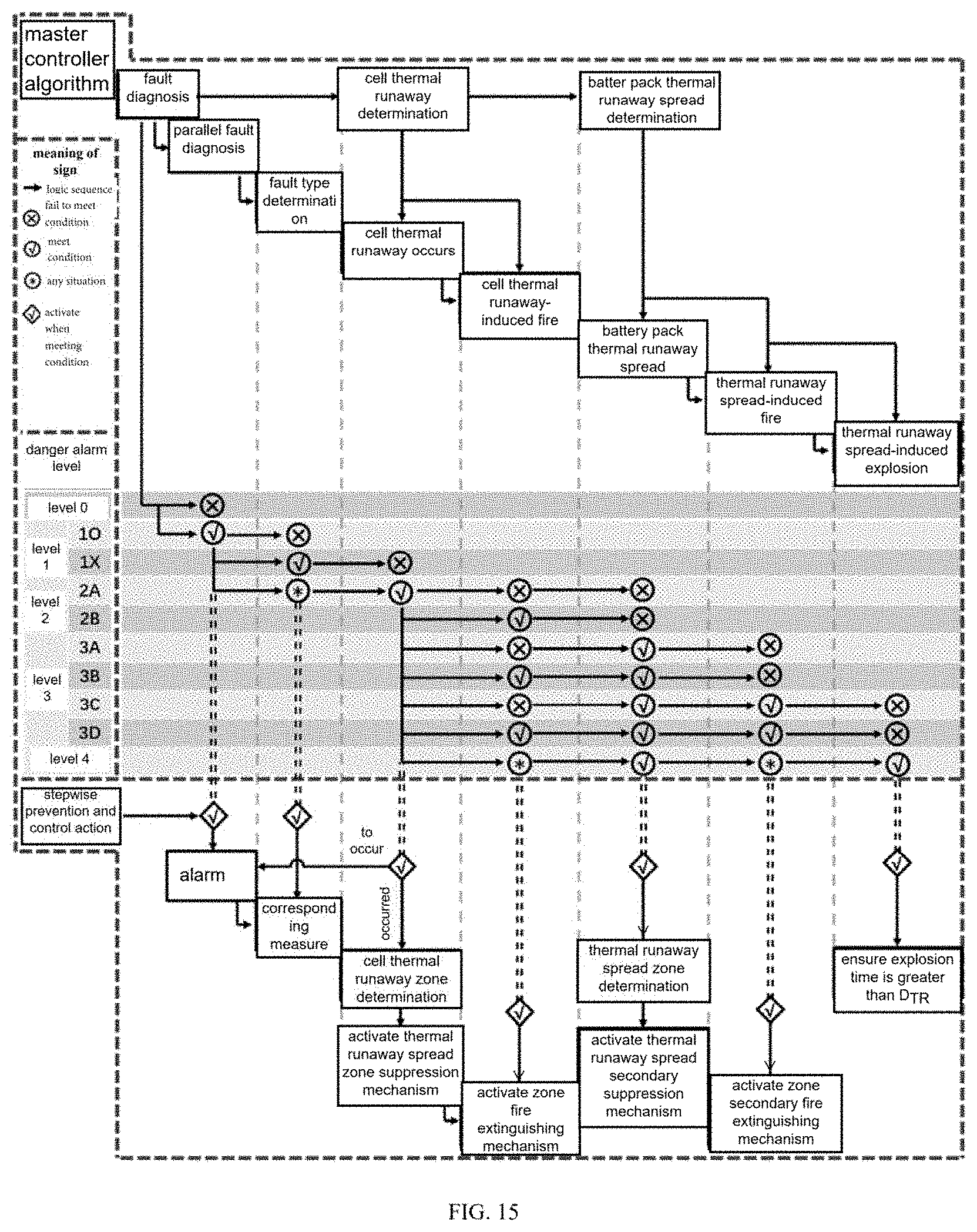
[0083] Referring to FIG. 15, a control logic of a power battery pack safety prevention and control system 10 for an electric vehicle is provided. The master controller 300 includes three main levels, i.e., a fault diagnosis device 310, a battery cell thermal runaway determination device 320, and a battery pack thermal runaway spread determination device 330. Each level corresponds to different prevention and control measures.
[0084] In the fault diagnosis, the provided parallel fault diagnosis function can diagnose different types of faults and determine a fault type, but no false alarm occurs. Alarms for different faults, levels of the alarmed faults are level 1. When the fault type cannot be determined, the level of the fault is level 1O. The fault level is a level 1X after the determination of the fault type, here X represents a specific fault type.
[0085] In the determination of the cell thermal runaway, a function of determining an occurrence of thermal runaway is provided. A determination device for determining an occurrence of the thermal runaway can predict a possibility of an occurrence of the thermal runaway of a battery cell within a period of time t 0. If it is predicted that thermal runaway may occur, an alarm mechanism is triggered. If the thermal runaway determination device determines that the thermal runaway occurs, an alarm is issued with an alarm level 2A. At the same time, a zone in which the cell with the thermal runaway is located is determined, and the thermal runaway spread zone suppression mechanism is turned on in the corresponding zone. After the determination of the occurrence of the cell thermal runaway, the cell is continuously monitored and it is determined whether a thermal runaway-induced fire occurs in the cell. If the cell catches fire, the alarm level is level 2B, and a zone fire extinguishing mechanism is turned on in a corresponding zone.
[0086] In the determination of the battery pack thermal runaway spread, a function of determination of thermal runaway spread in a battery pack is provided. If it is determined that the thermal runaway spread occurs in an adjacent zone of the battery pack but the cell does not catch fire, the alarm level is a level 3A. If it is determined that thermal runaway spread occurs in an adjacent zone of the battery pack and the cell catches fire, the alarm level is a level 3B. As for the alarm level 3A/3B, a thermal runaway spread secondary suppression mechanism is turned on in a zone in which the thermal runaway spread occurs. At the same time, it is determined whether a thermal runaway spread-induced fire occurs. If it is determined that the thermal runaway spread-induced fire occurs but a cell does not catch fire, the alarm level is a level 3C. If it is determined that the thermal runaway spread-induced fire occurs and a cell catches fired, the alarm level is a level 3D. As for the alarm level 3C/3D, a zone secondary fire extinguishing mechanism is turned on in a zone in which the thermal runaway spread-induced fire occurs. The controller continuously monitors the battery pack to determine whether the thermal runaway spread-induced explosion occurs. If an explosion occurs, the alarm level is level 4, and a time interval DTR from the cell thermal runaway to the battery pack explosion is recorded. During the battery system passive safety design, it should be ensured that the time interval DTR from the cell thermal runaway to the battery pack explosion is greater than the escape duration required by a person. In general, considering the situation where a person is trapped and needs to wait for the fire brigade in order to obtain rescue, thus the DTR should be greater than 30 minutes.
[0087] In an embodiment, in combination with the above-mentioned power battery pack safety prevention and control system and the contents in FIGS. 1 to 15, the present disclosure further provides a control method for a power battery pack safety prevention and control system for an electric vehicle, including the following steps:
[0088] S100: the signal collection device 200 acquires monitoring information of the battery pack 100, and transmits the monitoring information to the master controller 300;
[0089] S200: the master controller 300 generates a control instruction according to the monitoring information, and sends the control instruction to the stepwise prevention and control actuator 400;
[0090] S300, the stepwise prevention and control actuator 400 performs a prevention and control action according to the control instruction sent by the master controller 300.
[0091] In one embodiment, the step S200 may specifically include:
[0092] S210: one or more of the fault diagnosis device 310, the battery cell thermal runaway determination device 320, and the battery pack thermal runaway spread determination device 330 generate at least one control instruction according to the monitoring information, and send the at least one control instruction to the stepwise prevention and control actuator 400.
[0093] In an embodiment, the step S210 may specifically include:
[0094] S211: the internal short-circuit detector 311, the external short-circuit detector 312, the charge-discharge fault detector 313, the insulation failure detector 314, the collision detector 315, the liquid leakage and fire detector 316 and the overheat detector 317 respectively perform a parallel fault diagnosis on different types of faults, determine the fault type, and send a control instruction for a fault of level one to the stepwise prevention and control actuator 400 according to the different fault types.
[0095] In an embodiment, the control method may further include:
[0096] the electrochemical status determination device 303 acquires information of a battery with an extreme electrochemical status, performs a model-based electrochemical abnormal status detection, and outputs a detection result of an electrochemical status of the battery;
[0097] the thermogenesis status determination device 304 acquires information of a battery with an extreme thermogenesis status, performs a model-based thermogenesis abnormal status detection, and outputs a detection result of a thermogenesis status of the battery;
[0098] the processor 301 stores position and status information of the battery pack 100, and generates a control instruction of a prevention and control action;
[0099] the selector 302 screens an extreme battery based on an "average+difference" model;
[0100] the logic-arithmetic unit 305 performs a logic operation according to the detection results obtained by the electrochemical status determination device 303 and the thermogenesis status determination device 304, and outputs an operation result to the processor 301.
[0101] In an embodiment, the step S210 may specifically further include:
[0102] S212: the battery cell thermal runaway predictor 321 predicts a possibility of an occurrence of the battery cell thermal runaway, and the battery cell thermal runaway locator 322 determines a zone in which the battery cell thermal runaway occurs;
[0103] S213: the battery cell thermal runaway predictor 321 and the battery cell thermal runaway locator 322 send control instructions for a fault of level two to the stepwise prevention and control actuator 400 according to different possibilities of the battery cell thermal runaway and different zones in which the battery cell thermal runaway occurs.
[0104] In an embodiment, the step S210 may specifically include:
[0105] S214: the battery pack thermal runaway spread predictor 331 determines whether a thermal runaway spread occurs in the battery pack and an adjacent zone, and the battery pack thermal runaway spread locator 332 locates a zone in which the battery pack thermal runaway spread occurs;
[0106] S215: the battery pack thermal runaway spread predictor 331 and the battery pack thermal runaway spread locator 332 send control instructions for a fault of level three to the stepwise prevention and control actuator 400 according to different conditions of whether the thermal runaway spread occurs in the battery pack 100, a zone in which the battery pack thermal runaway spread occurs, whether the battery pack 100 has a thermal runaway spread-induced fire, and whether a battery cell catches fire.
[0107] In an embodiment, the step S210 may specifically include:
[0108] S216: the battery pack thermal runaway spread-induced fire determination device 333 determines whether a thermal runaway spread-induced fire occurs in the battery pack 100;
[0109] S217: the battery pack thermal runaway spread-induced explosion determination device 334 determines whether a thermal runaway spread-induced explosion occurs in the battery pack 100, and sends a control instruction for a fault of level four to the stepwise prevention and control actuator 400 if an explosion occurs;
[0110] S218: the timer 335 records a time interval from the battery cell thermal runaway to the explosion of the battery pack 100.
[0111] In an embodiment, the control method further includes one or more of the following steps:
[0112] the shutoff device 421 shuts off a faulty cell and a fault zone circuit; [0113] the isolating device 422 isolates a faulty cell, isolates a charge-discharge circuit, and shuts off a main circuit of the battery pack 100;
[0114] the heat flow passive guide device 431 passively guides flow of heat;
[0115] The heat flow active guide device 435 actively guides flow of heat;
[0116] the heat exchanger 438 implements heat exchange between the battery pack 100 and the outside world;
[0117] the combustible gas extraction device 439 implements outward discharging of a combustible gas.
[0118] In an embodiment, the fire extinguishing device 440 includes a fire extinguishing agent tank body 441, a fire extinguishing agent delivery pipeline 442, and a fire extinguishing agent injection valve body 443. The fire extinguishing agent tank body 441 is connected to the fire extinguishing agent injection valve body 443 through the fire extinguishing agent delivery pipeline 442. The fire extinguishing agent injection valve body 443 includes a fire extinguishing agent injection valve body 444 in a zone I and a fire extinguishing agent injection valve body 445 in a zone II.
[0119] The control method further includes: the fire extinguishing agent injection valve body 444 in the zone I and the fire extinguishing agent injection valve body 445 in the zone II complete injections of different doses of fire extinguishing agent.
[0120] In an embodiment, the present disclosure further provides a power battery pack safety prevention and control system for an electric vehicle, including a battery pack 100, a signal collection device 200, a master controller 300, and a stepwise prevention and control actuator 400.
[0121] The battery pack 100 is configured to power an electric vehicle.
[0122] One end of the signal collection device 200 is electrically connected to the battery pack 100; the other end of the signal collection device 200 is electrically connected to the master controller 300, and the signal collection device 200 is configured to acquire monitoring information of the battery pack 100 and transmit the monitoring information to the master controller 300.
[0123] The master controller 300 includes a fault diagnosis device 310, a battery cell thermal runaway determination device 320, and a battery pack thermal runaway spread determination device 330. The fault diagnosis device 310, the battery cell thermal runaway determination device 320, and the battery pack thermal runaway spread determination device 330 are respectively electrically connected to the stepwise prevention and control actuators 400, and are configured to send control instructions to the stepwise prevention and control actuator 400.
[0124] The stepwise prevention and control executor 400 is configured to perform a prevention and control action according to the control instructions sent by the fault diagnosis device 310, the battery cell thermal runaway determination device 320, and the battery pack thermal runaway spread determination device 330.
[0125] The fault diagnosis device 310 includes an internal short-circuit detector 311, an external short-circuit detector 312, a charge-discharge fault detector 313, an insulation failure detector 314, a collision detector 315, a liquid leakage and fire detector 316 and an overheat detector 317.
[0126] The internal short-circuit detector 311, the external short-circuit detector 312, the charge-discharge fault detector 313, the insulation failure detector 314, the collision detector 315, the liquid leakage and fire detector 316 and the overheat detector 317 are electrically connected to the signal collection device 200 respectively.
[0127] The internal short-circuit detector 311, the external short-circuit detector 312, the charge-discharge fault detector 313, the insulation failure detector 314, the collision detector 315, the liquid leakage and fire detector 316 and the overheat detector 317 are respectively configured to perform a parallel fault diagnosis on different types of faults, determine a fault type, and send a control instruction for a fault of level one to the stepwise prevention and control actuator 400 according to different fault types.
[0128] The battery pack thermal runaway spread determination device 330 further includes a battery pack thermal runaway spread-induced fire determination device 333, a battery pack thermal runaway spread-induced explosion determination device 334, and a timer 335.
[0129] The battery pack thermal runaway spread-induced fire determination device 333, the battery pack thermal runaway spread-induced explosion determination device 334, and the timer 335 are electrically connected to the signal collection device 200 respectively.
[0130] The battery pack thermal runaway spread-induced fire determination device 333 is configured to determine whether a thermal runaway spread-induced fire occurs in the battery pack 100.
[0131] The battery pack thermal runaway spread-induced explosion determination device 334 is configured to determine whether a thermal runaway spread-induced explosion occurs in the battery pack 100, and send a control instruction for a fault of level four to the stepwise prevention and control actuator 400 if an explosion occurs.
[0132] The timer 335 is electrically connected to the battery pack thermal runaway spread-induced explosion determination device 334, and is configured to record a time interval from the battery cell thermal runaway to the explosion of the battery pack 100.
[0133] The stepwise prevention and control actuator 400 includes an alarm device 410, a thermal runaway inducement suppression device 420, a thermal runaway zone suppression device 430, a fire extinguishing device 440, and a safety relief device 450 electrically connected to the master controller 300 respectively.
[0134] The thermal runaway inducement suppression device 420 includes a shutoff device 421 and an isolating device 422. The shutoff device 421 and the isolating device 422 are respectively provided as a device to perform a corresponding prevention and control action. The shutoff device 421 is configured to shut off a fault cell and a fault zone circuit. The isolating device 422 is configured to isolate a fault cell, isolate a charge-discharge circuit, and shut off a main circuit of the battery pack 100.
[0135] The various technical features in the above-mentioned embodiments can be arbitrarily combined. To simplify the description, all possible combinations of the technical features in the above-mentioned embodiments are not described herein. However, as long as there are no contradictions in the combinations of these technical features, all the combinations should be considered within the scope of the present disclosure.
[0136] The above-mentioned embodiments are merely several exemplary embodiments of the present disclosure, and their descriptions are more specific and detailed, but they should not be understood as limiting the scope of the present disclosure. It should be noted that, those skilled in the art can make various modifications and improvements without departing from the concept of the present disclosure, and these modifications and improvements all fall within the protection scope of the present disclosure. Therefore, the protection scope of the present disclosure shall be subject to the appended claims.
* * * * *
D00000
D00001
D00002
D00003
D00004
D00005
D00006
D00007
D00008
D00009
D00010
XML
uspto.report is an independent third-party trademark research tool that is not affiliated, endorsed, or sponsored by the United States Patent and Trademark Office (USPTO) or any other governmental organization. The information provided by uspto.report is based on publicly available data at the time of writing and is intended for informational purposes only.
While we strive to provide accurate and up-to-date information, we do not guarantee the accuracy, completeness, reliability, or suitability of the information displayed on this site. The use of this site is at your own risk. Any reliance you place on such information is therefore strictly at your own risk.
All official trademark data, including owner information, should be verified by visiting the official USPTO website at www.uspto.gov. This site is not intended to replace professional legal advice and should not be used as a substitute for consulting with a legal professional who is knowledgeable about trademark law.