Image Forming Apparatus And Operation Panel Unit Of The Image Forming Apparatus
SHINGAI; Hiroyuki
U.S. patent application number 16/830529 was filed with the patent office on 2020-10-01 for image forming apparatus and operation panel unit of the image forming apparatus. This patent application is currently assigned to Brother Kogyo Kabushiki Kaisha. The applicant listed for this patent is Brother Kogyo Kabushiki Kaisha. Invention is credited to Hiroyuki SHINGAI.
| Application Number | 20200310711 16/830529 |
| Document ID | / |
| Family ID | 1000004783657 |
| Filed Date | 2020-10-01 |


| United States Patent Application | 20200310711 |
| Kind Code | A1 |
| SHINGAI; Hiroyuki | October 1, 2020 |
IMAGE FORMING APPARATUS AND OPERATION PANEL UNIT OF THE IMAGE FORMING APPARATUS
Abstract
An operation panel unit is used for an image forming apparatus. The operation panel unit is configured to input various control instructions to the image forming apparatus. The operation panel unit includes a display portion, an NFC reading portion, and a USB port. The NFC reading portion and the USB port are disposed on different surfaces of the display portion.
| Inventors: | SHINGAI; Hiroyuki; (Nagoya-shi, JP) | ||||||||||
| Applicant: |
|
||||||||||
|---|---|---|---|---|---|---|---|---|---|---|---|
| Assignee: | Brother Kogyo Kabushiki
Kaisha Nagoya JP |
||||||||||
| Family ID: | 1000004783657 | ||||||||||
| Appl. No.: | 16/830529 | ||||||||||
| Filed: | March 26, 2020 |
| Current U.S. Class: | 1/1 |
| Current CPC Class: | G06F 3/1279 20130101; G06F 3/1236 20130101; G06F 3/1203 20130101 |
| International Class: | G06F 3/12 20060101 G06F003/12 |
Foreign Application Data
| Date | Code | Application Number |
|---|---|---|
| Mar 28, 2019 | CN | 201920406054.6 |
Claims
1. An operation panel unit used for an image forming apparatus, the operation panel unit being configured to input various control instructions to the image forming apparatus, the operation panel unit comprising: a display portion; an NFC reading portion; and a USB port; wherein the NFC reading portion and the USB port are disposed on different surfaces of the display portion.
2. The operation panel unit according to claim 1, wherein the NFC reading portion and the USB port are disposed at the same edge portion of the display portion.
3. The operation panel unit according to claim 1, wherein the NFC reading portion is disposed at one end side of the display portion in a left-right direction and the USB port is disposed at the other end side of the display portion opposite to the one end side in the left-right direction, and wherein the left-right direction is a left-right direction when a user views the display portion from a direction perpendicular to a display surface of the display portion.
4. The operation panel unit according to claim 1, wherein an NFC operation surface of the NFC reading portion is inclined with respect to a display surface of the display portion, the NFC reading portion is disposed at an edge portion of the display portion, and the USB port is disposed on a surface other than a surface defined the edge portion of the display portion.
5. The operation panel unit according to claim 1, wherein the USB port is located above the NFC reading portion in an up-down direction of the display portion, and the up-down direction is an up-down direction when a user views the display portion from a direction perpendicular to a display surface of the display portion.
6. The operation panel unit according to claim 1, wherein the display portion includes a pivot shaft and the display portion is pivotable about the pivot shaft with respect to image forming apparatus, and an insertion direction in which a USB device is inserted into the USB port is parallel to the pivot shaft.
7. An image forming apparatus comprising: an operation panel unit configured to input various control instructions to the image forming apparatus, the operation panel unit comprising: a display portion; an NFC reading portion; and a USB port; wherein the NFC reading portion and the USB port are disposed on different surfaces of the display portion.
Description
CROSS-REFERENCE TO RELATED APPLICATION
[0001] This application claims priority from Chinese Utility Model Application No. 201920406054.6 filed on Mar. 28, 2019, the content of which is incorporated herein by reference in its entirety.
TECHNICAL FIELD
[0002] Aspects of the disclosure relate to an image forming apparatus and an operation panel unit used for the image forming apparatus.
BACKGROUND
[0003] An operation panel unit used for an image forming apparatus is known. The operation panel unit includes a display portion and can be input various control instructions to the image forming apparatus by directly pressing a display surface of the display portion (e.g., a touch-panel type) or by using a button disposed near the display surface (e.g., a switch type). In addition, the operation panel unit further includes a near field communication (hereinafter referred to as NFC) function. When a mobile terminal and an NFC reading portion disposed on the operation panel unit are close to each other, data communication can be performed, thereby realizing functions such as user identification authentication and user terminal access.
[0004] However, when a USB port is disposed on the operation panel unit as described above and the mobile terminal using the NFC reading portion and a device using the USB port are present at the same time, the problems of mutual interference may occur due to position of arrangement.
SUMMARY
[0005] Aspects of the disclosure provide an operation panel unit used for an image forming apparatus, which avoids mutual interference when the mobile terminal using the NFC reading portion and the device using the USB port are present at the same time.
[0006] According to aspects of the disclosure, an operation panel unit may be used for an image forming apparatus and be configured to input various control instructions to the image forming apparatus. The operation panel unit may include a display portion, an NFC reading portion, and a USB port. The NFC reading portion and the USB port may be disposed on different surfaces of the display portion.
[0007] According to one or more aspects of the disclosure, an image forming apparatus may include an operation panel unit. The operation panel unit may be configured to input various control instructions to the image recording apparatus. The operation panel unit may include a display portion, an NFC reading portion, and a USB port. The NFC reading portion and the USB port may be disposed on different surfaces of the display portion.
BRIEF DESCRIPTION OF THE DRAWINGS
[0008] Aspects of the disclosure are illustrated by way of example and not by limitation in the accompanying figures in which like reference characters indicate similar elements.
[0009] FIG. 1 is a schematic view of an example of an image forming apparatus.
[0010] FIG. 2 is a schematic view of an example of an operation panel unit.
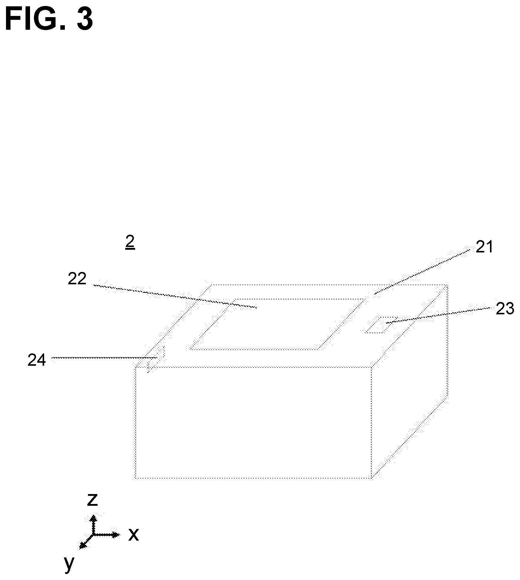
[0011] FIG. 3 is a schematic view of the other example of an operation panel unit.
[0012] FIG. 4 is a schematic view of the other example of an operation panel unit.
[0013] FIG. 5 is a schematic view of the other example of an operation panel unit.
DETAILED DESCRIPTION
[0014] Hereinafter, an embodiment of the present disclosure will be described with reference to the drawings. In each drawing, about components having the same function are denoted by the same reference mark.
[0015] FIG. 1 is a schematic view of an example of an image forming apparatus in the present disclosure. FIG. 2 is a schematic view of an example of an operation panel unit in the present disclosure.
[0016] As depicted in FIGS. 1 and 2, the image forming apparatus 1 includes the operation panel unit 2. The operation panel unit 2 is configured to input various control instruction to the image forming apparatus 1. The operation panel unit 2 includes a display portion 21, a display surface 22, an NFC reading portion 23, and a USB port 24. The display surface 22 is located at a substantially central position of an upper surface of the display portion 21. The NFC reading portion 23 is located on a surface of the display portion 21. The USB port 24 is located on the other surface of the display portion 21.
[0017] Preferably, in the present disclosure, the direction with respect to the operation panel unit 2 is defined as follows: a left-right direction when a user views from a direction perpendicular to the display surface 22 (i.e. an x-axis direction in FIGS. 1-5) is a first direction, a direction perpendicular to the first direction on the display surface 22 (i.e. a y-axis direction in FIGS. 1-5) is a second direction as an up-down direction. In FIG. 2, the USB port 23 is located above the NFC reading portion 23 in the second direction (i.e. the y-axis direction in FIGS. 1-5).
[0018] Preferably, in the present disclosure, a region of the display portion 21 in the vicinity of a one edge of a surface on which the display surface 22 is located is referred to as a one edge portion. As depicted in FIG. 2, the NFC reading portion 23 and the USB port 24 may be located at the same edge portion of the display portion 21.
[0019] Preferably, the NFC reading portion 23 and the USB port 24 may be located on a different edge portion of the display portion 21. For example, as depicted in FIG. 3, the NFC reading portion 23 and the USB port 24 are respectively located at opposite ends of the display portion 21 in the first direction (i.e. the x-axis direction in FIGS. 1-5), thereby completely avoiding mutual interference when the NFC reading portion and the USB port are used at the same time. The present disclosure is not limited to the example of depicted in FIG. 3, and the NFC reading portion 23 and the USB port 24 may be respectively located at opposite ends of the display portion 21 in the second direction (i.e. the y-axis direction in FIGS. 1-5).
[0020] Preferably, as depicted in FIG. 4, the present disclosure may also be configured such that a reading surface of the NFC reading portion 23 is inclined with respect to the display surface 22 to facilitate the use of the NFC reading portion 23. In this case, in order to avoid possible interference, it is necessary to dispose the NFC reading portion 23 and the USB port 21 at different edge portions of the display portion 21. That is, if the NFC reading portion 23 is disposed on the edge portion of the display portion 21 defined by an upper surface on which the display surface 22 is disposed and a side surface 21a, the USB port 24 is disposed on a surface of the display portion 21 other than the upper surface and the side surface 21a. For example, in FIG. 4, the USB port 24 is disposed on a side surface 21b of the display portion 21 adjacent to the side surface 21a. The USB port 24 may also be disposed on a side surface 21c opposite to the side surface 21a or on a side surface 21d opposite to the side surface 21b.
[0021] Preferably, as depicted in FIG. 5, in the present disclosure, the display portion 21 may further include a pivot shaft 25. This allows the display portion 21 to be configured to be pivotable with respect to image forming apparatus 1, thereby improving the convenience when using the NFC reading portion 23 and the USB port 24. In this case, in order to conveniently insert a USB device into the USB port 24, it is preferable that an insertion direction in which the USB device is inserted into the USB port 24 (i.e. a direction depicted by an arrow in FIG. 5) is parallel to the pivot shaft 25. Accordingly, when the USB device is inserted, the display portion 21 does not pivot, and the USB device may be smoothly inserted into the USB port 24.
[0022] Preferably, in FIG. 5, the pivot shaft 25 is disposed on the one surface of the display portion 21, however this is only one example, the present disclosure is not limited to thereto, the pivot shaft 25 may also be located inside the display portion 21.
[0023] As above, although the preferred illustrative embodiment of the present disclosure is described, the present disclosure is not limited to thereto, the various modifications are possible within the range which does not deviate from the meaning of the present disclosure.
[0024] For example, in the above embodiment, the USB port 24 is located above the NFC reading portion 23 in the second direction (i.e. the y-axis direction in FIGS. 1-5), however the USB port 24 may also be located below the NFC reading portion 23 in the second direction (i.e. the y-axis direction in FIGS. 1-5).
[0025] Furthermore, the various embodiments in the present disclosure are not independent of each other. As long as there are not particular combining obstacles, it is obvious that various combinations and modifications may be made according to the various embodiments.
* * * * *
D00000
D00001
D00002
D00003
D00004
D00005
XML
uspto.report is an independent third-party trademark research tool that is not affiliated, endorsed, or sponsored by the United States Patent and Trademark Office (USPTO) or any other governmental organization. The information provided by uspto.report is based on publicly available data at the time of writing and is intended for informational purposes only.
While we strive to provide accurate and up-to-date information, we do not guarantee the accuracy, completeness, reliability, or suitability of the information displayed on this site. The use of this site is at your own risk. Any reliance you place on such information is therefore strictly at your own risk.
All official trademark data, including owner information, should be verified by visiting the official USPTO website at www.uspto.gov. This site is not intended to replace professional legal advice and should not be used as a substitute for consulting with a legal professional who is knowledgeable about trademark law.