Force Sensing With An Electromagnetic Load
MARCHAIS; Emmanuel ; et al.
U.S. patent application number 16/569047 was filed with the patent office on 2020-10-01 for force sensing with an electromagnetic load. This patent application is currently assigned to Cirrus Logic International Semiconductor Ltd.. The applicant listed for this patent is Cirrus Logic International Semiconductor Ltd.. Invention is credited to Kathryn Rose HOLLAND, Eric LINDEMANN, Emmanuel MARCHAIS, Carl Lennart ST HL.
| Application Number | 20200309611 16/569047 |
| Document ID | / |
| Family ID | 1000004365554 |
| Filed Date | 2020-10-01 |


| United States Patent Application | 20200309611 |
| Kind Code | A1 |
| MARCHAIS; Emmanuel ; et al. | October 1, 2020 |
FORCE SENSING WITH AN ELECTROMAGNETIC LOAD
Abstract
A system for performing force sensing with an electromagnetic load may include a signal generator configured to generate a signal for driving an electromagnetic load and a processing subsystem configured to monitor at least one operating parameter of the electromagnetic load and determine a force applied to the electromagnetic load based on a variation of the at least one operating parameter.
| Inventors: | MARCHAIS; Emmanuel; (Austin, TX) ; HOLLAND; Kathryn Rose; (Austin, TX) ; ST HL; Carl Lennart; (Malmo, SE) ; LINDEMANN; Eric; (Boulder, CO) | ||||||||||
| Applicant: |
|
||||||||||
|---|---|---|---|---|---|---|---|---|---|---|---|
| Assignee: | Cirrus Logic International
Semiconductor Ltd. Edinburgh GB |
||||||||||
| Family ID: | 1000004365554 | ||||||||||
| Appl. No.: | 16/569047 | ||||||||||
| Filed: | September 12, 2019 |
Related U.S. Patent Documents
| Application Number | Filing Date | Patent Number | ||
|---|---|---|---|---|
| 62826327 | Mar 29, 2019 | |||
| Current U.S. Class: | 1/1 |
| Current CPC Class: | G01L 5/105 20130101; H02M 1/44 20130101; G01L 1/086 20130101 |
| International Class: | G01L 1/08 20060101 G01L001/08; G01L 5/10 20060101 G01L005/10 |
Claims
1. A system for performing force sensing with an electromagnetic load comprising: a signal generator configured to generate a signal for driving an electromagnetic load; and a processing subsystem configured to: monitor at least one operating parameter of the electromagnetic load; and determine a force applied to the electromagnetic load based on a variation of the at least one operating parameter.
2. The system of claim 1, wherein the electromagnetic load comprises a haptic transducer.
3. The system of claim 2, wherein the signal comprises a haptic waveform signal.
4. The system of claim 1, wherein the force is indicative of force applied to a host device comprising the electromagnetic load by a user of the host device.
5. The system of claim 1, wherein the processing subsystem is further configured to cause an occurrence of an action in response to determining that force has been applied to the electromagnetic load.
6. The system of claim 5, wherein the action comprises a modification of the signal for driving the electromagnetic load.
7. The system of claim 5, wherein the action comprises interaction with a user interface of a host device comprising the electromagnetic load.
8. The system of claim 5, wherein the action comprises monitoring a health indicator of a user of a host device comprising the electromagnetic load.
9. The system of claim 5, wherein the processing subsystem is further configured to cause the occurrence of the action if the variation of at least one operating parameter exceeds a threshold variation.
10. The system of claim 1, wherein the at least one operating parameter comprises at least one of a resonance frequency of the electromagnetic load, a back electromotive force of the electromagnetic load, a voltage across the electromagnetic load, a current through the electromagnetic load, a complex impedance of the electromagnetic load, and a quality factor of the electromagnetic load.
11. A method for performing force sensing with an electromagnetic load comprising: generating a signal for driving an electromagnetic load; monitoring at least one operating parameter of the electromagnetic load; and determining a force applied to the electromagnetic load based on a variation of the at least one operating parameter.
12. The method of claim 11, wherein the electromagnetic load comprises a haptic transducer.
13. The method of claim 12, wherein the signal comprises a haptic waveform signal.
14. The method of claim 11, wherein the force is indicative of force applied to a host device comprising the electromagnetic load by a user of the host device.
15. The method of claim 11, further comprising causing an occurrence of an action in response to determining that force has been applied to the electromagnetic load.
16. The method of claim 15, wherein the action comprises a modification of the signal for driving the electromagnetic load.
17. The method of claim 15, wherein the action comprises interaction with a user interface of a host device comprising the electromagnetic load.
18. The method of claim 15, wherein the action comprises monitoring a health indicator of a user of a host device comprising the electromagnetic load.
19. The method of claim 15, further comprising causing the occurrence of the action if the variation of at least one operating parameter exceeds a threshold variation.
20. The method of claim 11, wherein the at least one operating parameter comprises at least one of a resonance frequency of the electromagnetic load, a back electromotive force of the electromagnetic load, a voltage across the electromagnetic load, a current through the electromagnetic load, a complex impedance of the electromagnetic load, and a quality factor of the electromagnetic load.
Description
RELATED APPLICATIONS
[0001] The present disclosure claims priority to U.S. Provisional Patent Application Ser. No. 62/826,327, filed Mar. 29, 2019, which is incorporated by reference herein in its entirety.
[0002] The present disclosure is also related to U.S. patent application Ser. No. 16/556,849, filed Aug. 30, 2019 ("Tracking Application 1"), U.S. patent application Ser. No. 16/556,897, filed Aug. 30, 2019 ("Tracking Application 2"), and U.S. patent application Ser. No. 16/559,238, filed Sep. 3, 2019 ("Tracking Application 3", and together with Tracking Application 1 and Tracking Application 2, the "Tracking Applications"), each of which is incorporated by reference herein in its entirety.
FIELD OF DISCLOSURE
[0003] The present disclosure relates in general to tracking a resonant frequency of a transducer, for example a haptic transducer, and driving such transducer at or near its resonant frequency.
BACKGROUND
[0004] Vibro-haptic transducers, for example linear resonant actuators (LRAs), are widely used in portable devices such as mobile phones to generate vibrational feedback to a user. Vibro-haptic feedback in various forms creates different feelings of touch to a user's skin, and may play increasing roles in human-machine interactions for modern devices.
[0005] An LRA may be modelled as a mass-spring electro-mechanical vibration system. When driven with appropriately designed or controlled driving signals, an LRA may generate certain desired forms of vibrations. For example, a sharp and clear-cut vibration pattern on a user's finger may be used to create a sensation that mimics a mechanical button click. This clear-cut vibration may then be used as a virtual switch to replace mechanical buttons.
[0006] FIG. 1 illustrates an example of a vibro-haptic system in a device 100. Device 100 may comprise a controller 101 configured to control a signal applied to an amplifier 102. Amplifier 102 may then drive a vibrational actuator (e.g., haptic transducer) 103 based on the signal. Controller 101 may be triggered by a trigger to output to the signal. The trigger may for example comprise a pressure or force sensor on a screen or virtual button of device 100.
[0007] Among the various forms of vibro-haptic feedback, tonal vibrations of sustained duration may play an important role to notify the user of the device of certain predefined events, such as incoming calls or messages, emergency alerts, and timer warnings, etc. In order to generate tonal vibration notifications efficiently, it may be desirable to operate the haptic actuator at its resonance frequency.
[0008] The resonance frequency f.sub.0 of a haptic transducer may be approximately estimated as:
f 0 = 1 2 .pi. CM ( 1 ) ##EQU00001##
where C is the compliance of the spring system, and M is the equivalent moving mass, which may be determined based on both the actual moving part in the haptic transducer and the mass of the portable device holding the haptic transducer.
[0009] Due to sample-to-sample variations in individual haptic transducers, mobile device assembly variations, temporal component changes caused by aging, and use conditions such as various different strengths of a user gripping of the device, the vibration resonance of the haptic transducer may vary from time to time.
[0010] FIG. 2 illustrates an example of a linear resonant actuator (LRA) modelled as a linear system. LRAs are non-linear components that may behave differently depending on, for example, the voltage levels applied, the operating temperature, and the frequency of operation. However, these components may be modelled as linear components within certain conditions. In this example, the LRA is modelled as a third order system having electrical and mechanical elements. In particular, Re and Le are the DC resistance and coil inductance of the coil-magnet system, respectively; and Bl is the magnetic force factor of the coil. The driving amplifier outputs the voltage waveform V(t) with the output impedance Ro. The terminal voltage V.sub.T(t) may be sensed across the terminals of the haptic transducer. The mass-spring system 201 moves with velocity u(t).
SUMMARY
[0011] In accordance with the teachings of the present disclosure, the disadvantages and problems associated with existing approaches for sensing application of force in a host device may be reduced or eliminated.
[0012] In accordance with embodiments of the present disclosure, a system for performing force sensing with an electromagnetic load may include a signal generator configured to generate a signal for driving an electromagnetic load and a processing subsystem configured to monitor at least one operating parameter of the electromagnetic load and determine a force applied to the electromagnetic load based on a variation of the at least one operating parameter.
[0013] In accordance with these and other embodiments of the present disclosure, a method for performing force sensing with an electromagnetic load may include generating a signal for driving an electromagnetic load, monitoring at least one operating parameter of the electromagnetic load, and determining a force applied to the electromagnetic load based on a variation of the at least one operating parameter.
[0014] Technical advantages of the present disclosure may be readily apparent to one having ordinary skill in the art from the figures, description and claims included herein. The objects and advantages of the embodiments will be realized and achieved at least by the elements, features, and combinations particularly pointed out in the claims.
[0015] It is to be understood that both the foregoing general description and the following detailed description are examples and explanatory and are not restrictive of the claims set forth in this disclosure.
BRIEF DESCRIPTION OF THE DRAWINGS
[0016] A more complete understanding of the present embodiments and advantages thereof may be acquired by referring to the following description taken in conjunction with the accompanying drawings, in which like reference numbers indicate like features, and wherein:
[0017] FIG. 1 illustrates an example of a vibro-haptic system in a device, as is known in the art;
[0018] FIG. 2 illustrates an example of a Linear Resonant Actuator (LRA) modelled as a linear system, as is known in the art; and
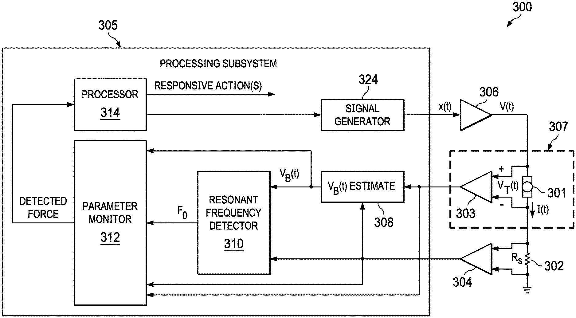
[0019] FIG. 3 illustrates selected components of an example host device incorporating force sensing using an electromagnetic load of the host device, in accordance with embodiments of the present disclosure.
DETAILED DESCIPTION
[0020] The description below sets forth example embodiments according to this disclosure. Further example embodiments and implementations will be apparent to those having ordinary skill in the art. Further, those having ordinary skill in the art will recognize that various equivalent techniques may be applied in lieu of, or in conjunction with, the embodiment discussed below, and all such equivalents should be deemed as being encompassed by the present disclosure.
[0021] Various electronic devices or smart devices may have transducers, speakers, and acoustic output transducers, for example any transducer for converting a suitable electrical driving signal into an acoustic output such as a sonic pressure wave or mechanical vibration. For example, many electronic devices may include one or more speakers or loudspeakers for sound generation, for example, for playback of audio content, voice communications and/or for providing audible notifications.
[0022] Such speakers or loudspeakers may comprise an electromagnetic actuator, for example a voice coil motor, which is mechanically coupled to a flexible diaphragm, for example a conventional loudspeaker cone, or which is mechanically coupled to a surface of a device, for example the glass screen of a mobile device. Some electronic devices may also include acoustic output transducers capable of generating ultrasonic waves, for example for use in proximity detection type applications and/or machine-to-machine communication.
[0023] Many electronic devices may additionally or alternatively include more specialized acoustic output transducers, for example, haptic transducers, tailored for generating vibrations for haptic control feedback or notifications to a user. Additionally or alternatively, an electronic device may have a connector, e.g., a socket, for making a removable mating connection with a corresponding connector of an accessory apparatus, and may be arranged to provide a driving signal to the connector so as to drive a transducer, of one or more of the types mentioned above, of the accessory apparatus when connected. Such an electronic device will thus comprise driving circuitry for driving the transducer of the host device or connected accessory with a suitable driving signal. For acoustic or haptic transducers, the driving signal may generally be an analog time varying voltage signal, for example, a time varying waveform.
[0024] FIG. 3 illustrates selected components of an example host device 300 incorporating force sensing using an electromagnetic load 301 of host device 300, in accordance with embodiments of the present disclosure. Host device 300 may include, without limitation, a mobile device, home application, a vehicle, and/or any other system, device, or apparatus that includes a human-machine interface. Electromagnetic load 301 may include any suitable load with a complex impedance, including without limitation a haptic transducer, a loudspeaker, a microspeaker, a piezoelectric transducer, or other suitable transducer.
[0025] In operation, a signal generator 324 of a processing subsystem 305 of host device 300 may generate a signal x(t) (which, in some embodiments, may be a waveform signal, such as a haptic waveform signal or audio signal). Signal x(t) may in turn be amplified by amplifier 306 to generate the driving signal V(t) for driving electromagnetic load 301. Responsive to driving signal V(t), a sensed terminal voltage V.sub.T(t) of electromagnetic load 301 may be converted to a digital representation by a first analog-to-digital converter (ADC) 303. Similarly, sensed current l(t) may be converted to a digital representation by a second ADC 304. Current l(t) may be sensed across a shunt resistor 302 having resistance R.sub.s coupled to a terminal of electromagnetic load 301. The terminal voltage V.sub.T(t) may be sensed by a terminal voltage sensing block 307, for example a volt meter.
[0026] As shown in FIG. 3, processing subsystem 305 may include a back-EMF estimate block 308 that may estimate back-EMF voltage V.sub.B(t). In general, back EMF voltage V.sub.B(t) may not be directly measured from outside of the haptic transducer. However, the terminal voltage V.sub.T(t) measured at the terminals of the haptic transducer may be related to V.sub.B(t) by:
V T ( t ) = V B ( t ) + Re I ( t ) + Le dI ( t ) dt ( 2 ) ##EQU00002##
where the parameters are defined as described with reference to FIG. 2. Consequently, back-EMF voltage V.sub.B(t) may be estimated according to equation (2) which may be rearranged as:
V B ( r ) = V T ( r ) - Re I ( t ) - Le dI ( t ) dt ( 3 ) ##EQU00003##
[0027] In some embodiments, back-EMF estimate block 308 may be implemented as a digital filter with a proportional and parallel difference path. The estimates of DC resistance Re and inductance Le may not need to be accurate (e.g., within an approximate 10% error may be acceptable), and thus, fixed values from an offline calibration or from a data sheet specification may be sufficient. As an example, in some embodiments, back-EMF estimate block 308 may determine estimated back-EMF voltage V.sub.B(t) in accordance with the teachings of Tracking Application 3.
[0028] Also as depicted in FIG. 3, processing subsystem 305 may include a resonant frequency detector 310 configured to estimate a resonance frequency f.sub.0 of electromagnetic load 301. As shown, resonant frequency detector 310 may be configured to estimate resonance frequency f.sub.0 based on sensed current l(t) and estimated back-EMF voltage V.sub.B(t) using one or more of the techniques described in the Tracking Applications. However, in some embodiments, one or more other measured quantities associated with electromagnetic load 301 may be used to determine its resonance frequency f.sub.0.
[0029] A parameter monitor 312 of processing subsystem 305 may receive signals indicative of one or more of resonance frequency f.sub.0, sensed current l(t), terminal voltage V.sub.T(t), and estimated back-EMF voltage V.sub.B(t), and based on one or more of such parameters, determine whether a force has been applied (e.g., by a user of host device 300) to electromagnetic load 301. Based on such detected force, a processor 314 of processing subsystem 305 may take one or more responsive actions as described in greater detail below.
[0030] In some embodiments, the determination of whether a force has been applied may be based on other parameters derived from one or more of resonance frequency f.sub.0, sensed current l(t), terminal voltage V.sub.T(t), and estimated back-EMF voltage V.sub.B(t), such as, for example, a complex impedance of electromagnetic load 301 (or change to such complex impedance) and/or a quality factor (or change to such quality factors) may be estimated from sensed current l(t), terminal voltage V.sub.T(t), and/or estimated back-EMF voltage V.sub.B(t) as described in Tracking Application 2 and Tracking Application 3.
[0031] To further illustrate, in response to driving signal V(t) being reproduced at electromagnetic load 301 (e.g., a haptic effect, playback of sounds, etc.), a user may grip or otherwise apply force to host device 300. For example, a haptic effect and/or playback of sounds (e.g., a ringtone) may provide to a user an indication of an incoming phone call, text message, electronic mail, or other electronic communication. A force applied by the user upon electromagnetic load 301 (e.g., either directly or indirectly by force applied to an enclosure of host device 300) may lead to a shift in one or more parameters (e.g., resonance frequency f.sub.0, impedance) of electromagnetic load 301. Thus, processing subsystem 305 may monitor such one or more parameters, determine based on such one or more parameters whether a force has been applied on electromagnetic load 301, and undertake a responsive action if force is detected.
[0032] Accordingly, electromagnetic load 301 may simultaneously act as an output transducer/actuator in addition to an input force sensor, in which a change in gripping force applied to host device 300 is detected as a change in one or more operating parameters (e.g., impedance, resonance frequency f.sub.0, sensed current l(t), terminal voltage V.sub.T(t), estimated back-EMF voltage V.sub.B(t), complex impedance, quality factor, and/or another parameter) of electromagnetic load 301. The magnitude of change of the one or more operating parameters may provide an indication of a magnitude of force (or change of force) applied to host device 300. Thus, processing subsystem 305 may apply one or more thresholds to the change in the one or more operating parameters (e.g., a change of 1%-2% of the magnitude of the operating parameters). For example, if an operating parameter in interest changes by less than a threshold percentage, parameter monitor 312 may not even process such change as an application of force. However, if the operating parameter in interest changes by more than the threshold percentage, parameter monitor 312 may process such change as an application of force, and take an appropriate response action. In some embodiments, a second threshold (or additional thresholds) may be present, such that changes in an operating parameter beyond such additional thresholds may lead to other response actions.
[0033] Although the foregoing contemplates detection of a force event in response to a change in one or more operating parameters, in some embodiments, more sophisticated approaches may be used to detect force events. For example, in some embodiments, a machine learning classifier such as a Support Vector Machine (SVM), Convolutional Neural Network (CNN), and/or classifier may be used to extract features of one or more operation parameter changes corresponding to force events and from such changes determine what type of force event has occurred.
[0034] As mentioned, based on a presence and/or magnitude of force applied to host device 300 as sensed by electromagnetic load 301, processor 314 may provide one or more responsive actions in response to the applied force. For example, in some embodiments, such one or more responsive actions may include altering signal x(t) responsive to force, thus modifying a haptic effect generated by electromagnetic load 301 (e.g., when electromagnetic load 301 comprises a vibrational actuator). As a specific example, the haptic effect a user perceives may vary based on how firmly the user grips a host device. In order create a steady haptic effect to a user, it may be desirable to reduce a responsive haptic effect as detected grip force increases. As another example, in these and other embodiments, such one or more responsive actions may include processor 314 causing one or more user interface events to occur at a display device (not explicitly shown) of host device 300 (e.g., via the interaction of processor altering signal x(t)) responsive to force. As a further example, in these and other embodiments, such one or more responsive actions may include performing health diagnostics responsive to force (e.g., force, including a reaction time in applying the force, may be indicative of motor reflex of the user).
[0035] The use of an electromagnetic load 301 as an input force sensor may have many advantages. For example, such use may avoid a need for some mechanical and/or other dedicated force sensing buttons on host device 300. In addition, such use may provide another user mode of interaction with host device 300 that does not require access to a screen, touch sensor, microphone, or other external mechanical device.
[0036] As used herein, when two or more elements are referred to as "coupled" to one another, such term indicates that such two or more elements are in electronic communication or mechanical communication, as applicable, whether connected indirectly or directly, with or without intervening elements.
[0037] This disclosure encompasses all changes, substitutions, variations, alterations, and modifications to the example embodiments herein that a person having ordinary skill in the art would comprehend. Similarly, where appropriate, the appended claims encompass all changes, substitutions, variations, alterations, and modifications to the example embodiments herein that a person having ordinary skill in the art would comprehend. Moreover, reference in the appended claims to an apparatus or system or a component of an apparatus or system being adapted to, arranged to, capable of, configured to, enabled to, operable to, or operative to perform a particular function encompasses that apparatus, system, or component, whether or not it or that particular function is activated, turned on, or unlocked, as long as that apparatus, system, or component is so adapted, arranged, capable, configured, enabled, operable, or operative. Accordingly, modifications, additions, or omissions may be made to the systems, apparatuses, and methods described herein without departing from the scope of the disclosure. For example, the components of the systems and apparatuses may be integrated or separated. Moreover, the operations of the systems and apparatuses disclosed herein may be performed by more, fewer, or other components and the methods described may include more, fewer, or other steps. Additionally, steps may be performed in any suitable order. As used in this document, "each" refers to each member of a set or each member of a subset of a set.
[0038] Although exemplary embodiments are illustrated in the figures and described below, the principles of the present disclosure may be implemented using any number of techniques, whether currently known or not. The present disclosure should in no way be limited to the exemplary implementations and techniques illustrated in the drawings and described above.
[0039] Unless otherwise specifically noted, articles depicted in the drawings are not necessarily drawn to scale.
[0040] All examples and conditional language recited herein are intended for pedagogical objects to aid the reader in understanding the disclosure and the concepts contributed by the inventor to furthering the art, and are construed as being without limitation to such specifically recited examples and conditions. Although embodiments of the present disclosure have been described in detail, it should be understood that various changes, substitutions, and alterations could be made hereto without departing from the spirit and scope of the disclosure.
[0041] Although specific advantages have been enumerated above, various embodiments may include some, none, or all of the enumerated advantages. Additionally, other technical advantages may become readily apparent to one of ordinary skill in the art after review of the foregoing figures and description.
[0042] To aid the Patent Office and any readers of any patent issued on this application in interpreting the claims appended hereto, applicants wish to note that they do not intend any of the appended claims or claim elements to invoke 35 U.S.C. .sctn. 112(f) unless the words "means for" or "step for" are explicitly used in the particular claim.
* * * * *
D00000
D00001
D00002
XML
uspto.report is an independent third-party trademark research tool that is not affiliated, endorsed, or sponsored by the United States Patent and Trademark Office (USPTO) or any other governmental organization. The information provided by uspto.report is based on publicly available data at the time of writing and is intended for informational purposes only.
While we strive to provide accurate and up-to-date information, we do not guarantee the accuracy, completeness, reliability, or suitability of the information displayed on this site. The use of this site is at your own risk. Any reliance you place on such information is therefore strictly at your own risk.
All official trademark data, including owner information, should be verified by visiting the official USPTO website at www.uspto.gov. This site is not intended to replace professional legal advice and should not be used as a substitute for consulting with a legal professional who is knowledgeable about trademark law.