Split Bay Forced Draft Air-Cooled Heat Exchanger
Goldsmith, JR.; James D. ; et al.
U.S. patent application number 16/836204 was filed with the patent office on 2020-10-01 for split bay forced draft air-cooled heat exchanger. The applicant listed for this patent is Chart Energy & Chemicals, Inc.. Invention is credited to James D. Goldsmith, JR., Timothy L. Pearce, JR..
| Application Number | 20200309461 16/836204 |
| Document ID | / |
| Family ID | 1000004765100 |
| Filed Date | 2020-10-01 |


| United States Patent Application | 20200309461 |
| Kind Code | A1 |
| Goldsmith, JR.; James D. ; et al. | October 1, 2020 |
Split Bay Forced Draft Air-Cooled Heat Exchanger
Abstract
A split bay forced draft air-cooled heat exchanger includes first and second bay sub-assemblies. Each sub-assembly includes a tube bundle, a plenum half positioned under the tube bundle and base beams supporting the tube bundle and the plenum half. Also included is a fan assembly having a fan, a fan motor and a drive assembly and a machinery mount upon which the fan assembly is mounted. The machinery mount is attached to base beams of the first bay sub-assembly and is configured to removably attach to base beams of the second sub-assembly with the fan configured to force air into a plenum made up of the plenum halves and across the tube bundles.
| Inventors: | Goldsmith, JR.; James D.; (Katy, TX) ; Pearce, JR.; Timothy L.; (Sugar Land, TX) | ||||||||||
| Applicant: |
|
||||||||||
|---|---|---|---|---|---|---|---|---|---|---|---|
| Family ID: | 1000004765100 | ||||||||||
| Appl. No.: | 16/836204 | ||||||||||
| Filed: | March 31, 2020 |
Related U.S. Patent Documents
| Application Number | Filing Date | Patent Number | ||
|---|---|---|---|---|
| 62827599 | Apr 1, 2019 | |||
| Current U.S. Class: | 1/1 |
| Current CPC Class: | F28D 1/024 20130101; F28D 1/0435 20130101 |
| International Class: | F28D 1/04 20060101 F28D001/04; F28D 1/02 20060101 F28D001/02 |
Claims
1. A split bay forced draft air-cooled heat exchanger comprising: a. a first bay sub-assembly including: i) a first tube bundle; ii) a first plenum half positioned under the first tube bundle; iii) a plurality of first base beams supporting the first tube bundle and the first plenum half; b. a second bay sub-assembly including: i) a second tube bundle; ii) a second plenum half positioned under the second tube bundle; iii) a plurality of second base beams supporting the second tube bundle and the second plenum half; c. a fan assembly including a fan, a fan motor and a drive assembly; d. a machinery mount upon which the fan assembly is mounted, said machinery mount attached to at least some of the plurality of first base beams and configured to removably attach to at least some of the plurality of second base beams so that the first and second bay sub-assemblies are secured together with the fan configured to force air into a plenum made up of the first and second plenum halves and across the first and second tube bundles.
2. The heat exchanger of claim 1 wherein the first tube bundle and the first plenum half are mounted to the plurality of first base beams by a plurality of first column supports and the second tube bundle and the second plenum half are mounted to the plurality of second base beams by a plurality of second column supports.
3. The heat exchanger of claim 2 wherein the first tube bundle includes a first tube bundle frame that is supported by the plurality of first column supports and the second tube bundle includes a second tube bundle frame that is supported by the plurality of second column supports
4. The heat exchanger of claim 1 wherein the machinery mount is also removably attached to at least some of the plurality of first base beams.
5. The heat exchanger of claim 1 wherein the first plenum half includes a semi-circular first fan opening bordered by a downward extending first fan ring half circle and the second plenum half includes a semi-circular second fan opening bordered by a downward extending second fan ring half circle.
6. The heat exchanger of claim 1 wherein the first plenum half includes a first open side and the second plenum half includes a second open side and further comprising a first structural support traversing the first open side and a second structural support traversing the second open side.
7. The heat exchanger of claim 6 wherein each of the first and second structural supports includes a truss.
8. A split bay forced draft air-cooled heat exchanger comprising: a. a first bay sub-assembly including: i) a first tube bundle; ii) a first plenum half positioned under the first tube bundle; iii) a plurality of first column supports connected to the first tube bundle and the first plenum half; iv) a plurality of first base beams positioned one each across bottom portions of at least two pairs of the plurality of first column supports so that the plurality of first base beams and the plurality of first column supports are configured to support the first tube bundle and the first plenum half on a surface; b. a second bay sub-assembly including: i) a second tube bundle; ii) a second plenum half positioned under the second tube bundle; iii) a plurality of second column supports connected to the second tube bundle and the second plenum half; iv) a plurality of second base beams positioned one each across bottom portions of at least two pairs of the plurality of second column supports so that the plurality of second base beams and the plurality of first column supports are configured to support the first tube bundle and the first plenum half on a surface; c. a fan assembly including a fan, a fan motor and a drive assembly; d. a machinery mount upon which the fan assembly is mounted, said machinery mount attached to a pair of the plurality of first base beams and configured to removably attach to a pair of the plurality of second base beams so that the first and second bay sub-assemblies are secured together with the fan configured to force air into a plenum made up of the first and second plenum halves and across the first and second tube bundles.
9. The heat exchanger of claim 8 wherein the first tube bundle includes a first tube bundle frame that is supported by the plurality of first column supports and the second tube bundle includes a second tube bundle frame that is supported by the plurality of second column supports
10. The heat exchanger of claim 8 wherein the machinery mount is also removably attached to a pair of the plurality of first base beams.
11. The heat exchanger of claim 8 wherein the first plenum half includes a semi-circular first fan opening bordered by a downward extending first fan ring half circle and the second plenum half includes a semi-circular second fan opening bordered by a downward extending second fan ring half circle.
12. The heat exchanger of claim 8 wherein the first plenum half includes a first open side and the second plenum half includes a second open side and further comprising a first structural support traversing the first open side and a second structural support traversing the second open side.
13. The heat exchanger of claim 12 wherein each of the first and second structural supports includes a truss.
14. A method of transporting a forced draft air-cooled heat exchanger comprising the steps of: a. providing a first bay sub-assembly having a first tube bundle with a first plenum half under the first tube bundle, where the first tube bundle and the first plenum half are supported on a pair of first base beams; b. providing a second bay sub-assembly having a second tube bundle with a second plenum half under the second tube bundle, where the second tube bundle and the second plenum half are supported on a pair of second base beams; c. providing a machinery mount upon which is mounted a fan, a fan motor and a drive assembly, wherein said fan includes a plurality of removable blades; d. removing some of the plurality of removable blades from the fan; e. transporting the first bay sub-assembly, the second bay sub-assembly, the machinery mount, the fan motor and the removed fan blades.
15. The method of claim 14 further comprising the step of removing the fan motor from the machinery mount prior to step e.
16. The method of claim 15 further comprising the steps of: f. installing the fan motor in the machinery mount; g. installing the removed fan blades into the fan; h. securing the first and second bay sub-assemblies together by securing the machinery mount to at least one of the first and second base beams.
17. The method of claim 14 wherein the machinery mount is connected to the first bay sub-assembly.
18. The method of claim 14 further comprising the steps of: f. installing the removed fan blades into the fan; g. securing the first and second bay sub-assemblies together by securing the machinery mount to at least one of the first and second base beams.
19. A split bay forced draft air-cooled heat exchanger comprising: a. a first bay sub-assembly including: i) a first tube bundle; ii) a first tube bundle frame within which the first tube bundle is mounted; iii) a first plenum half positioned under the first tube bundle; iv) a first machinery mount positioned under the first plenum half; v) a first outer support member attached to an outer end of the first machinery mount and the first plenum half; vi) a first inner support member removably attached to an inner end of the first machinery mount and the first tube bundle frame; b. a second bay sub-assembly including: i) a second tube bundle; ii) a second tube bundle frame within which the second tube bundle is mounted; iii) a second plenum half positioned under the second tube bundle; iv) a second machinery mount positioned under the second plenum half; v) a second outer support member attached to an outer end of the second machinery mount and the second plenum half; vi) a second inner support member removably attached to an inner end of the second machinery mount and the second tube bundle frame; c. a fan assembly including a fan, a fan motor and a drive assembly, said fan assembly mounted on the first or second machinery mount; d. said inner end of the first machinery mount configured to removably attach to the inner end of the second machinery mount, after the first and second inner support members are detached from the first and second bay sub-assemblies, so that the first and second bay sub-assemblies are secured together with the fan configured to force air into a plenum made up of the first and second plenum halves and across the first and second tube bundles.
20. The heat exchanger of claim 19 wherein each of the first and second tube bundle frames includes a pair of elongated side plates to which the inner support members are attached.
21. The heat exchanger of claim 20 wherein the pair of elongated side plates are joined by a pair of tube bundle headers.
22. The heat exchanger of claim 19 wherein the first and second outer support members are attached directly to the first and second plenum halves, respectively.
23. The heat exchanger of claim 19 wherein the first and second outer support members are attached to the first and second tube bundle frames, respectively.
Description
CLAIM OF PRIORITY
[0001] This application claims the benefit of U.S. Provisional Application No. 62/827,599, filed Apr. 1, 2019, the contents of which are hereby incorporated by reference.
FIELD OF THE INVENTION
[0002] The present disclosure relates generally to forced draft air-cooled heat exchangers and, more specifically, to forced draft air-cooled heat exchangers with a split bay design.
BACKGROUND
[0003] Heat exchangers are widely used for cooling or heating process fluid streams using a second cooling or heating fluid stream. Air-cooled heat exchangers, as the name implies, use air as the second cooling fluid and typically employ a fan to drive the air over tube bundles through which the process fluids being cooled flow. Such heat exchangers may be of the induced draft exchanger type or the forced draft exchanger type. Induced draft exchangers feature tube bundle(s) located on the suction side of the fan (with the fan typically positioned above the bundle). Forced draft exchangers feature tube bundle(s) located on the discharge side of the fan (with the fan typically positioned below the bundle). The tube bundles in both types of designs are typically organized in bays with each bay containing one or more tube bundles serviced by one or more fans. Each bay also includes the structure for holding the tube bundle(s) and fan(s), plenum(s) and other attendant equipment.
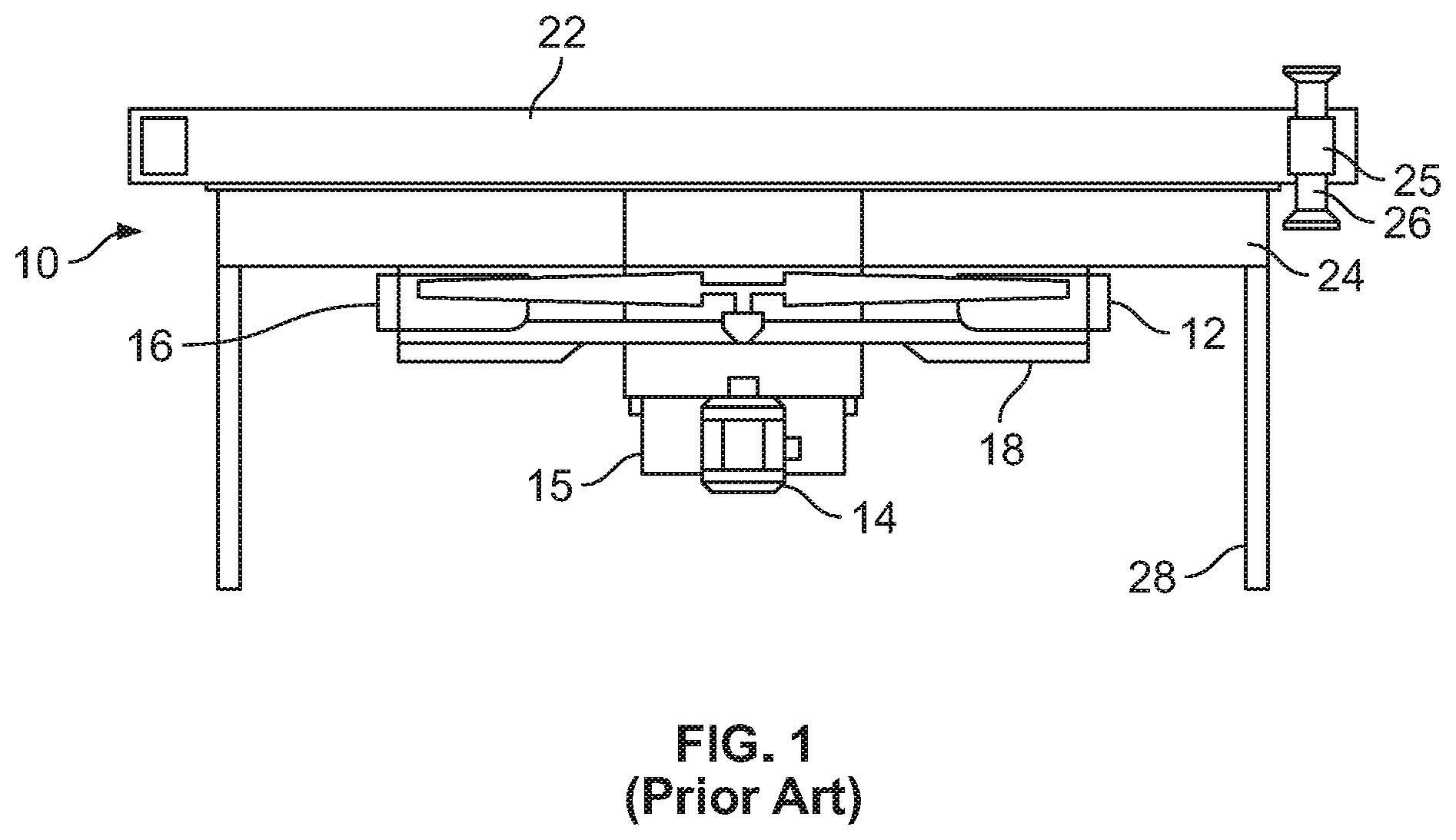
[0004] An example of a prior art forced draft heat exchanger bay is indicated in general at 10 in FIG. 1, and features a fan and plenum below the tube bundle, a fan shaft below the tube bundle and a machinery mount below the tube bundle. More specifically, as illustrated in FIG. 1, the bay 10 includes a fan 12 which is powered by a fan motor and drive assembly 14, which are supported by a machinery mount 15. To focus and direct air flow, a fan ring 16 surrounds the fan and an inlet bell 18 is provided. A tube bundle 22 and a plenum 24 are positioned above the fan, where the latter equalizes air pressure for more even distribution of the air flow from the fan across the tube bundle. A header 25 featuring nozzles 26 directs a process fluid stream into and out of the tube bundle so that the process fluid stream is cooled by the air flow generated by the fan. Column supports 28 support the bay in an installation.
[0005] Air-cooled heat exchanger designs are limited to sizes that can be economically transported. Many countries, states or providences have restrictions regarding the width, height and length of equipment that pass through their domain. These restrictions have an impact on the number of air-cooled heat exchanger bays that will be required to do a given duty of an installation.
SUMMARY
[0006] There are several aspects of the present subject matter which may be embodied separately or together in the devices and systems described and claimed below. These aspects may be employed alone or in combination with other aspects of the subject matter described herein, and the description of these aspects together is not intended to preclude the use of these aspects separately or the claiming of such aspects separately or in different combinations as set forth in the claims appended hereto.
[0007] In one aspect a split bay forced draft air-cooled heat exchanger features a first bay sub-assembly including a first tube bundle, a first plenum half positioned under the first tube bundle and a plurality of first base beams supporting the first tube bundle and the first plenum half. The heat exchanger also features a second bay sub-assembly including a second tube bundle, a second plenum half positioned under the second tube bundle, a plurality of second base beams supporting the second tube bundle and the second plenum half. The heat exchanger also includes a fan assembly including a fan, a fan motor and a drive assembly. The heat exchanger also includes a machinery mount upon which the fan assembly is mounted. The machinery mount is attached to at least some of the plurality of first base beams and is configured to removably attach to at least some of the plurality of second base beams so that the first and second bay sub-assemblies are secured together with the fan configured to force air into a plenum made up of the first and second plenum halves and across the first and second tube bundles.
[0008] In another aspect, a split bay forced draft air-cooled heat exchanger features a first bay sub-assembly including a first tube bundle, a first plenum half positioned under the first tube bundle, a plurality of first column supports connected to the first tube bundle and the first plenum half and a plurality of first base beams positioned one each across bottom portions of at least two pairs of the plurality of first column supports so that the plurality of first base beams and the plurality of first column supports are configured to support the first tube bundle and the first plenum half on a surface. The heat exchanger also has a second bay sub-assembly including a second tube bundle, a second plenum half positioned under the second tube bundle, a plurality of second column supports connected to the second tube bundle and the second plenum half and a plurality of second base beams positioned one each across bottom portions of at least two pairs of the plurality of second column supports so that the plurality of second base beams and the plurality of first column supports are configured to support the first tube bundle and the first plenum half on a surface. The heat exchanger also includes a fan assembly including a fan, a fan motor and a drive assembly and a machinery mount upon which the fan assembly is mounted. The machinery mount is attached to a pair of the plurality of first base beams and is configured to removably attach to a pair of the plurality of second base beams so that the first and second bay sub-assemblies are secured together with the fan configured to force air into a plenum made up of the first and second plenum halves and across the first and second tube bundles.
[0009] In still another aspect, a method for transporting a forced draft air-cooled heat exchanger includes the steps of: providing a first bay sub-assembly having a first tube bundle with a first plenum half under the first tube bundle, where the first tube bundle and the first plenum half are supported on a pair of first base beams; providing a second bay sub-assembly having a second tube bundle with a second plenum half under the second tube bundle, where the second tube bundle and the second plenum half are supported on a pair of second base beams; providing a machinery mount upon which is mounted a fan, a fan motor and a drive assembly, wherein said fan includes a plurality of removable blades; removing some of the plurality of removable blades from the fan; transporting the first bay sub-assembly, the second bay sub-assembly, the machinery mount, the fan motor and the removed fan blades.
[0010] In still another aspect, a split bay forced draft air-cooled heat exchanger features a first bay sub-assembly including a first tube bundle, a first tube bundle frame within which the first tube bundle is mounted, a first plenum half positioned under the first tube bundle, a first machinery mount positioned under the first plenum half, a first outer support member attached between an outer end of the first machinery mount and the first tube bundle frame and a first inner support member removably attached between an inner end of the first machinery mount and the first tube bundle frame. A second bay sub-assembly includes a second tube bundle, a second tube bundle frame within which the second tube bundle is mounted, a second plenum half positioned under the second tube bundle, a second machinery mount positioned under the second plenum half, a second outer support member attached between an outer end of the second machinery mount and the second tube bundle frame and a second inner support member removably attached between an inner end of the second machinery mount and the second tube bundle frame. A fan assembly includes a fan, a fan motor and a drive assembly. The fan assembly is mounted on the first or second machinery mount. The inner end of the first machinery mount is configured to removably attach to the inner end of the second machinery mount, after the first and second inner support members are detached from the first and second machinery mounts and the first and second tube bundle frames, so that the first and second bay sub-assemblies are secured together with the fan configured to force air into a plenum made up of the first and second plenum halves and across the first and second tube bundles.
BRIEF DESCRIPTION OF THE DRAWINGS
[0011] FIG. 1 is a side elevational view of a prior art forced draft heat exchanger bay;
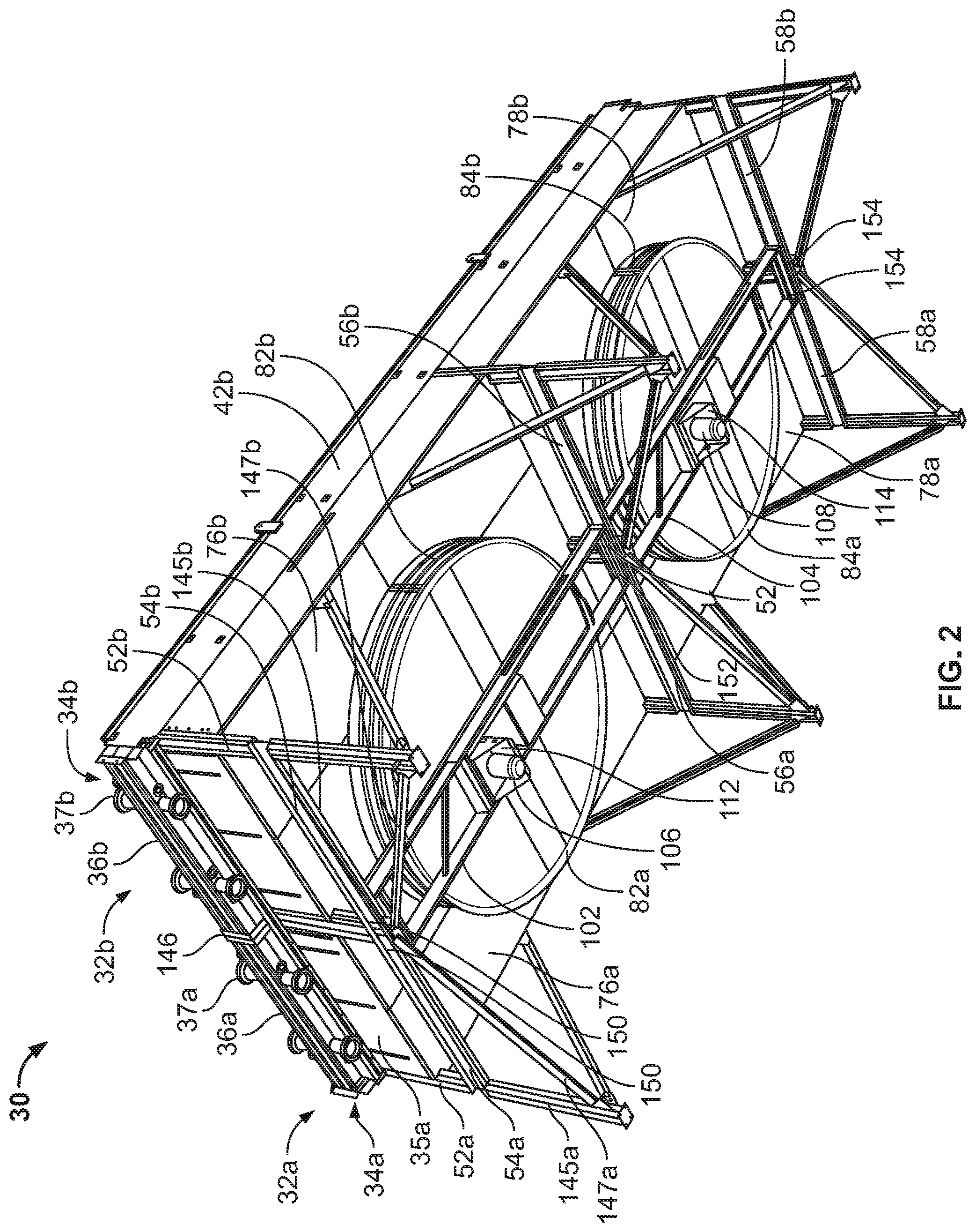
[0012] FIG. 2 is a bottom perspective view of an embodiment of the split bay forced draft air-cooled heat exchanger of the disclosure after assembly with the fans omitted;
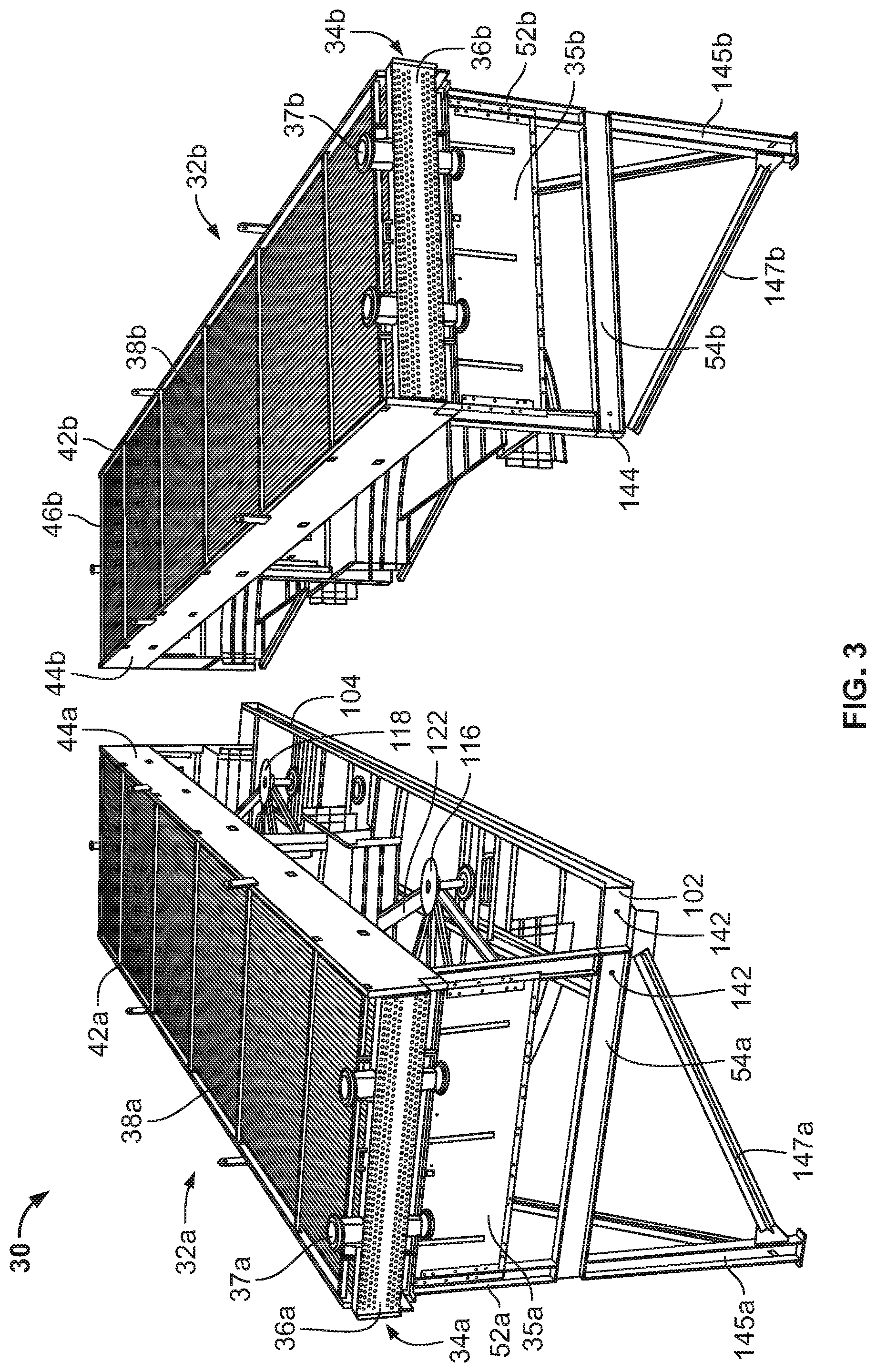
[0013] FIG. 3 is a top perspective view of the split bay forced draft air-cooled heat exchanger of FIG. 2 with the fans, fan motors and associated drive assemblies installed but prior to assembly of the bay sub-assemblies;
[0014] FIG. 4 is a top perspective view of the unassembled bay sub-assemblies of FIG. 3 with the tube bundles and fans, fan motors and associated drive assemblies omitted;
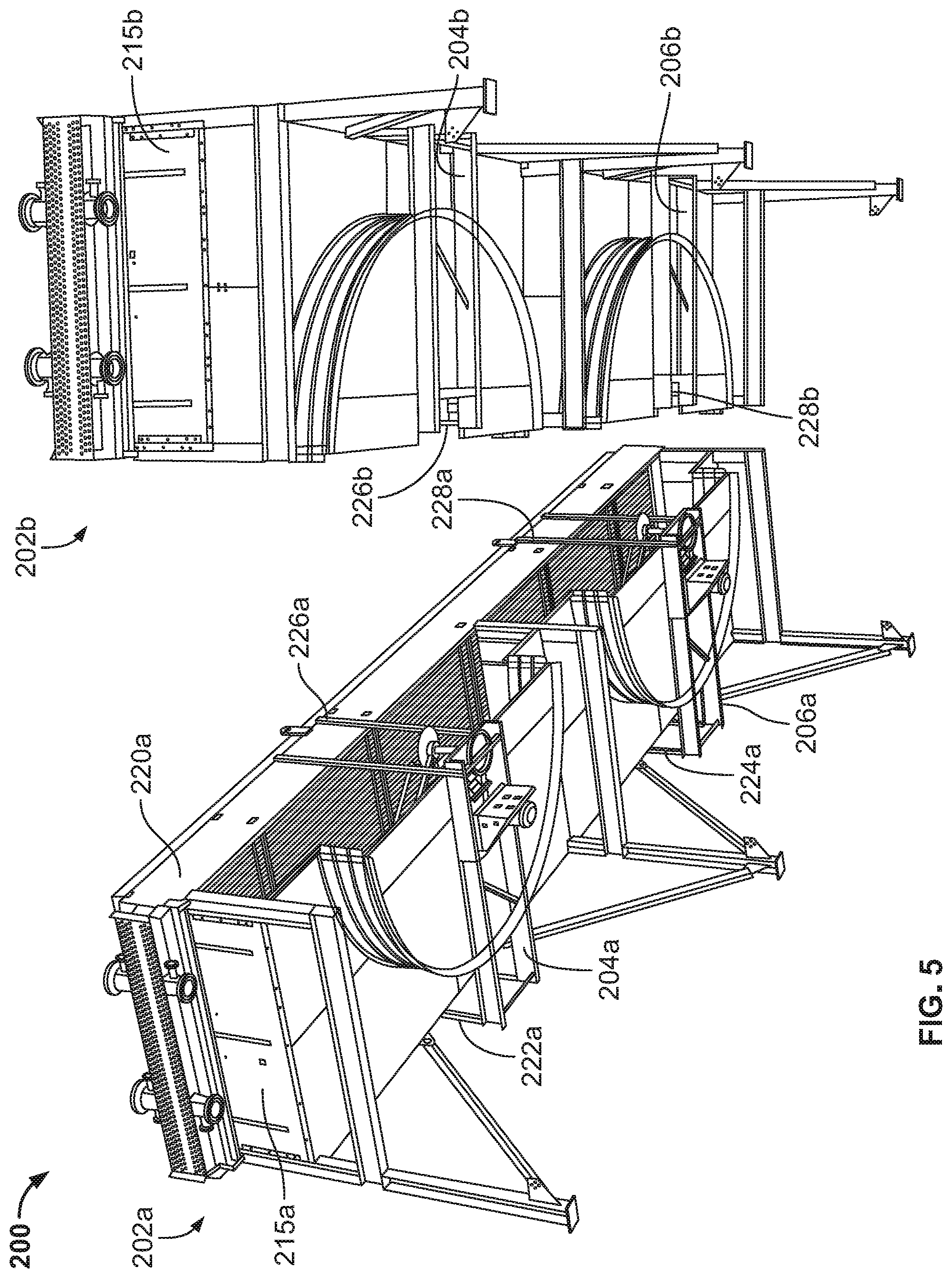
[0015] FIG. 5 is a bottom perspective view of an alternative embodiment of the split bay forced draft air-cooled heat exchanger of the disclosure featuring a perpendicular machinery mount prior to assembly of the bay sub-assemblies;
[0016] FIG. 6 is a right-side perspective view of one of the bay sub-assemblies of the split bay forced draft air-cooled heat exchanger of FIG. 5;
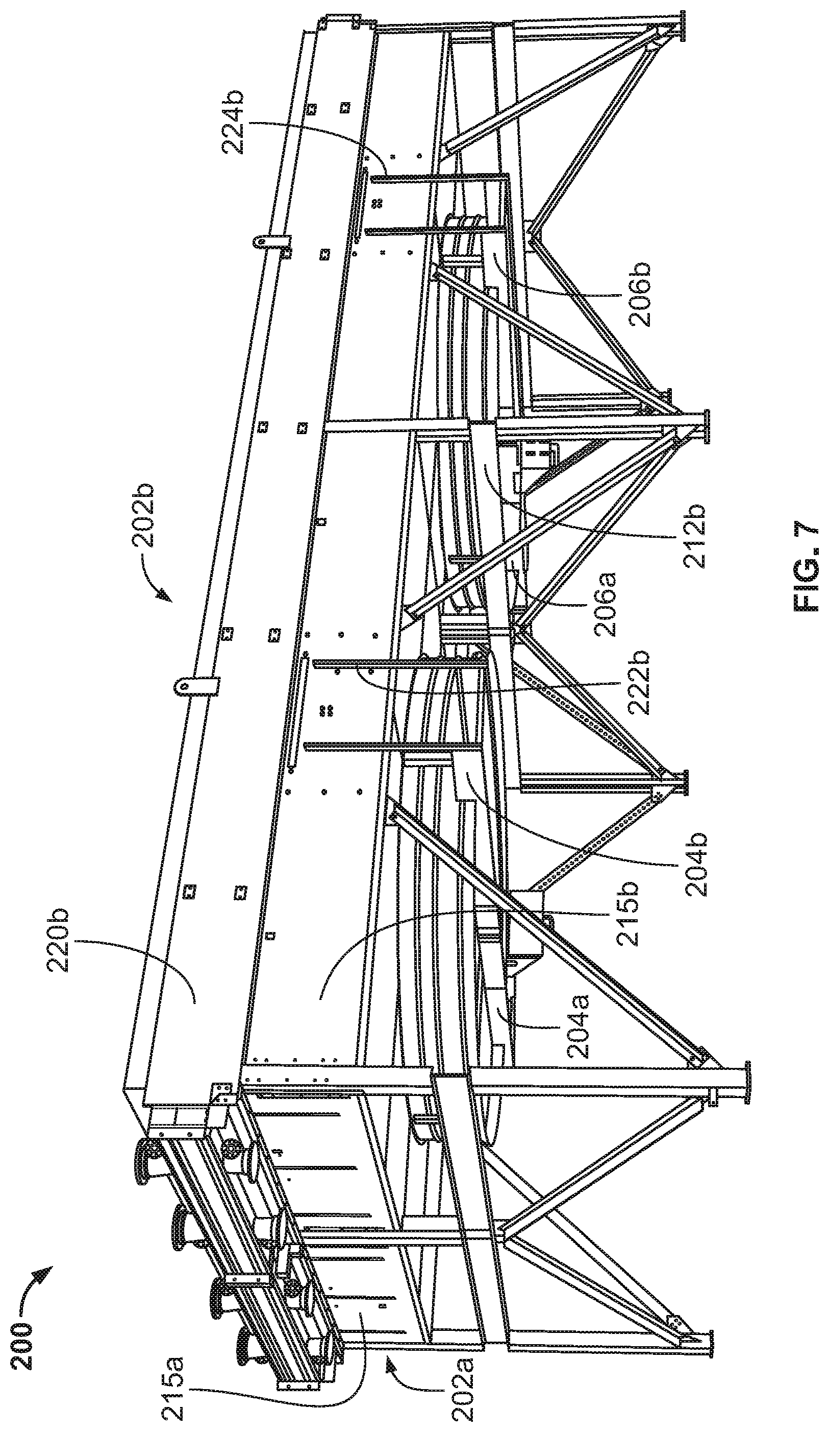
[0017] FIG. 7 is a right-side perspective view of the split bay forced draft air-cooled heat exchanger of FIG. 5 after assembly.
DETAILED DESCRIPTION OF EMBODIMENTS
[0018] In accordance with the disclosure, embodiments of a forced draft air-cooled heat exchanger featuring a split bay design are provided. Bays are shipped in two separate assemblies and bolted together in the field.
[0019] By splitting the bay design into two pieces, a much larger bay may be manufactured because the bay can be fabricated and shipped in two assemblies that share common fans and mechanical drives across the width of the bay. For example, instead of providing two bays with three (3) fans and mechanical drives each (a total of six fans and six mechanical drives), a manufacturer can design and fabricate one large bay fabricated in two assemblies with up to three (3) large fans and three (3) mechanical drives for the single larger bay. As an example only, using the technology of the disclosure, it is plausible to design a unit 33' wide.times.70' long and use only two fans and two mechanical drives. This gives a manufacturer a competitive advantage to be able to supply one larger bay in place of two smaller bays at a competitive price without the use of offshore suppliers.
[0020] Embodiments of the heat exchanger of the disclosure are specifically designed to provide support for the weight of the entire sub-assembly (half of the bay). It allows for the machinery mount (structure that includes the motor, sprockets, belt, bearings, or motor/gearbox/gearmotor, and fan shafts) to be installed on one half of the bay to later be bolted to the second half of the bay. The structure of the unit is designed to also act as the structural members to support the unit during shipping without the need to add shipping beams that are later discarded at the job site.
[0021] An embodiment of a split forced draft air-cooled heat exchanger bay is indicated in general at 30 in FIGS. 2 and 3. The fan blades and associated drive components have been omitted from FIG. 2 for clarity. As illustrated in FIGS. 2 and 3, the bay 30 includes a first bay sub-assembly, indicated in general at 32a, and a second bay sub-assembly, indicated in general at 32b.
[0022] First bay sub-assembly 32a includes a first tube bundle, indicated in general at 34a, positioned above a first plenum half 35a. First tube bundle includes headers 36a (FIGS. 2 and 3) and 46a (FIG. 3) having inlet and outlets, such as nozzles 37a, for the process fluid being cooled and a number of tubes 38a running between the headers 36a and 46a. As known in the art, each of the tubes 38a has an inlet and an outlet in fluid communication with the headers 36a and 46a so that process fluid entering the inlets of one of the headers flows through the tubes and exits the outlets of the other header. Alternative tube and header configurations known in the art may be used in place of the tubes 38a and headers 36a and 46a including, but not limited to, U-shaped and serpentine tubes.
[0023] As illustrated in FIG. 3, the tube bundle 34a includes a pair of elongated side plates 42a and 44a that support the headers 36a and 46a and tubes 38a that form the tube bundle 34a. The tube bundle 34b features a construction similar to tube bundle 34a and includes headers 36b and 46b and tubes 38b as well as a tube bundle frame formed by elongated side plates 42b and 44b as well as the headers 36b and 46b.
[0024] As illustrated in FIGS. 2 and 3, the frame of tube bundle 34a is mounted to the top ends of column supports 52a. While three pairs of the column supports 52a (six individual column supports) are illustrated, an alternative number may be used. The bottom ends of the pairs of the column supports 52a are mounted upon base beams 54a, 56a and 58a (FIG. 2). The frame of tube bundle 34b is similarly mounted to the tops of column supports 52b, with the bottoms of the column supports 52b mounted upon base beams 54b, 56b and 58b (FIG. 2).
[0025] As examples only, and as illustrated in FIGS. 2-4, the column supports 52a and 52b, and the base beams 54a, 56a, 58a and 54b, 56b, 58b may be steel I-beams. Alternative types of beams or members and materials known in the art may be used instead.
[0026] As best illustrated in FIG. 4, where first plenum half is indicated in general at 35a, the first plenum half includes sidewalls 62a and 64a which extend between three of the column supports 52a. The first plenum half 35a also includes a pair of end walls 66a and 68a that extend between corresponding pairs of column supports and a divider wall 72a that extends between a corresponding pair of column supports. Each wall may optionally be provided with support members 74a. Floor panels 76a and 78a are joined to the bottom ends of corresponding side, end and divider walls, as shown in FIG. 4, and each includes a semi-circular fan opening bordered by a downward extending fan ring half circle 82a and 84a.
[0027] First plenum half end walls 66a and 68a, divider wall 72a, floor 76a and floor 78a define open sides indicated in general at 86a and 88a. A pair of structural supports 92a and 94a traverses the open sides 86a and 88a, respectively, and support the first plenum half 35a and half circle of the fan ring during both operation and in transit. As an example only, and as illustrated, the structural supports 92a and 94a may include a truss structure.
[0028] With continued reference to FIG. 4, the second plenum half 35b includes sidewalls 62b and 64b which extend between three of the column supports 52b. The second plenum half 35b also includes a pair of end walls 66b and 68b that extend between corresponding pairs of column supports and a divider wall 72b that extends between a corresponding pair of column supports. Each wall may optionally be provided with support members 74b. Floor panels 76b and 78b are joined to the bottom ends of corresponding side, end and divider walls, as shown in FIG. 4, and each includes a semi-circular fan opening bordered by a downward extending fan ring half 82b and 84b.
[0029] Second plenum half end walls 66b and 68b, divider wall 72b, floor 76b and floor 78b define open sides indicated in general at 86b and 88b. A pair of structural supports 92b and 94b traverses the open sides 86b and 88b, respectively, and support the first plenum half 35b and half circle of the fan ring in both operation and in transit. As an example only, and as illustrated, the structural supports 92b and 94b may include a truss structure.
[0030] While the first and second plenum halves 35a and 35b each feature a single dividing wall and two semi-circular fan openings, the dividing walls may be omitted or additional dividing walls may be included and an alternative number of semi-circular fan openings (and associated half circle fan rings), including one or more than two, may be present in a single plenum half.
[0031] The plenum half sidewalls, end walls, dividing walls and floors and the fan rings are each preferably made of sheet metal (although other materials may be used).
[0032] With reference to FIGS. 2 and 3, first bay sub-assembly 32a features a pair of machinery mounts 102 and 104 upon which fan motors 106 and 108 (FIG. 2) are mounted via motor brackets 112 and 114, respectively. In addition, fan hubs 116 and 118 (FIG. 3) are rotationally mounted to the machinery mounts 102 and 104, respectively. The fan hubs 116 and 118 receive fan blades 122 and 124, respectively and are turned by the fan motors 106 and 108 using drive assemblies that are also mounted on the machinery mounts 102 and 104. Such drive assemblies are well known in the art and may include, as examples only, sprockets and chains, belts and/or drive shafts.
[0033] As illustrated in FIG. 4, machinery mount 102 includes a pair of elongated and opposing side beams 126 and 128 and opposing end beams 130 and 132, as well as a cross member 134. The cross member 134 includes an opening to which the fan hub may be rotationally mounted. Machinery mount 104 features a similar structure.
[0034] As illustrated in FIGS. 2-4, each of the machinery mounts 102 and 104 is designed to run lengthwise along the assembly of one-half of the bay. There is one machinery mount per fan, with the machinery mounts arranged end to end.
[0035] The length of the installed machinery mounts span the entire length of the bay, as illustrated in FIGS. 2 and 3, because the machinery mount cannot be supported by the tube bundles. This is because any support suspending from the bundles would interfere with the fans' operation. Furthermore, a machinery mount designed for the full width of the bay would defeat the purpose of minimizing the width of an assembly for shipment.
[0036] The three base beams 54a, 56a and 58a at the bottom of the first bay sub-assembly 32a and the three base beams 54b, 56b and 58b at the bottom of the second bay sub-assembly 32b each feature fastener openings (for example, 140, 142 and 144 in FIG. 3) that align with fastener openings formed in the end beams of the machinery mounts 102 and 104 when the bay sub-assemblies are joined in the manner shown in FIG. 2. In a preferred embodiment, bolts pass through the fastener openings of the base beams and the machinery mounts to secure the two bay sub-assemblies 32a and 32b together (FIG. 2).
[0037] As a result, the two bay sub-assembly halves 32a and 32b are bolted together by bolted connections, such as at the locations indicated by arrows 150, 152 and 154 in FIG. 2, and the machinery mounts 102 and 104 are secured to each bay sub-assembly half in a manner that provides the rigidity necessary to prevent vibration issues with the bay. In addition, the abutting flanges of adjacent column supports are bolted, or otherwise secured, together. Angle brackets may be positioned on the inwardly facing edges of each of the floor panels 76a, 76b, 78a and 78b and bolted, or otherwise secured, together to aid in securing the two bay sub-assembly halves together. Angle brackets may also be positioned on the ends of each of the fan ring half circles 82a, 82b, 84a and 84b and bolted, or otherwise secured, together to aid in securing the two bay sub-assembly halves together. In alternative embodiments, the base beams may feature face plates abutting one another when the sub-assembly halves are positioned together as shown in FIG. 2, with fasteners such as bolts securing the face plates, and thus the end-to-end base beams, together. Assembly of the bay sub-assemblies 32a and 32b, as illustrated in FIG. 2, results in two circular fan openings being formed and bordered by two completed fan rings formed from the joined fan ring circle halves 82a and 82b and 84a and 84b. In addition, the joined plenum halves 35a and 35b form dedicated plenums for each of the fan openings. Alternative embodiments may provide an alternative number of fan openings and plenums.
[0038] As illustrated in FIGS. 2 and 3, the base beams of bay sub-assembly 32a may be supported by legs 145a, and corresponding struts 147a, while the base beams of sub-assembly 32b may similarly be supported by legs 145b and corresponding struts 147b.
[0039] In embodiments where a truss (FIG. 4 at 92a, 92b and 94a and 94b) is provided for the plenum halves, the need for an air seal between the two assembled bay sub-assembly halves, at the location indicated by arrow 146 of FIG. 2, may be avoided. Such an air seal, however, may optionally be provided.
[0040] Prior to shipping, the bay sub-assembly 32a with the machinery mounts 102 and 104 will have the fans mounted with half of the fan blades removed (as illustrated in FIG. 3), with the fan blades to be installed at the job site. Furthermore, the fan motors (106 and 108 of FIG. 3) may will be removed for shipping. In alternative embodiments, the fan motors may remain installed for shipping.
[0041] The base beams (54a, 54b, 56a, 56b and 58a and 58b of FIG. 2) remain part of the assembled unit and also act as shipping beams for transit of the bay sub-assemblies 32a and 32b.
[0042] An alternative embodiment of a split forced draft air-cooled heat exchanger bay of the disclosure is indicated in general at 200 in FIGS. 5 and 7. The bay 200 includes a first bay sub-assembly, indicated in general at 202a (FIGS. 5 and 7), and a second bay sub-assembly, indicated in general at 202b (FIGS. 5-7).
[0043] The primary difference between the embodiment of FIGS. 5-7 and the embodiments described above is that the machinery mounts 204a, 206a, 204b and 206b run perpendicular to the length (i.e. across the width) of each bay sub-assembly. Given that the remaining components of each bay sub-assembly are the same as described above in previous embodiments, they will not be numbered in, and described with regard to, FIGS. 5-7.
[0044] First bay sub-assembly 202a features a pair of machinery mounts 204a and 206a. Second bay sub-assembly 202b features a pair of machinery mounts 204b and 206b. Fan assemblies, including fans, fan motors and associated drive systems, are mounted on machinery mounts 204b and 206b.
[0045] The machine mounts 204a and 206a are supported at their outer ends by the sidewall of the plenum 215a via outer support members 222a and 224a (FIG. 5). Outer support members 222a and 224a may be attached to the plenum directly (as illustrated) or alternatively via attachment to the tube bundle frame 220a. The inner ends of machine mounts 204a and 206a are supported by the tube bundle frame 220a by inner support members 226a and 228a (FIG. 5).
[0046] The machine mounts 204b and 206b are supported at their outer ends by the sidewall of plenum 215b via outer support members 222b and 224b (FIGS. 6 and 7). Outer support members 222b and 224b may be attached to the plenum directly (as illustrated) or alternatively via attachment to the tube bundle frame 220b. The inner ends of machine mounts 204b and 206b are supported by inner support members 226b and 228b (FIG. 5) by tube bundle frame 220b (FIGS. 6 and 7).
[0047] The inner and outer support members of FIGS. 5-7 may be elongated plates, I-beams, trusses or any other structural members or assemblies known in the art and may be constructed of, as an example only, steel or any other high-strength and durable material.
[0048] The inner and outer support members secure the components of each sub-assembly 202a and 202b together during shipping, which occurs when the bay sub-assemblies are in the configurations illustrated in FIG. 5. The inner support members 226a, 228a, 226b and 228b are removed at the job site, so that the two bay sub-assemblies 202a and 202b may be joined in the manner illustrated in FIG. 7. The outer support members 222a, 224a, 222b and 224b remain installed after assembly, as illustrated in FIG. 7.
[0049] The bay sub-assemblies are joined together in the configuration illustrated in FIG. 7 by joining the inner ends of machinery mounts 204a and 204b together and the inner ends of machinery mounts 206a and 206b together. This may be accomplished by providing the inner ends of the machinery mounts with face plates or cross members and then bolting the opposing face plates or cross members together. Alternatively, brackets and bolts or other fastening arrangements and/or fasteners known in the art may be used. The remaining portions of the bay sub-assemblies are secured together as well using the fastening arrangements described for the above embodiments.
[0050] As illustrated in FIG. 7, when the bay sub-assemblies are assembled to form the complete bay, the machinery mounts joined end to end run across the width of the entire bay. There is one fan assembly per joined machinery mount pair.
[0051] Embodiments of the disclosure provide forced draft air-cooled heat exchanger bay sub-assemblies that have the structural integrity necessary to provide support during transportation. The embodiments support the plenum and fan ring, as well as the fan and mechanical drive system, both during shipping and operation.
[0052] While the preferred embodiments of the disclosure have been shown and described, it will be apparent to those skilled in the art that changes and modifications may be made therein without departing from the spirit of the disclosure, the scope of which is defined by the following claims.
* * * * *
D00000
D00001
D00002
D00003
D00004
D00005
D00006
D00007
XML
uspto.report is an independent third-party trademark research tool that is not affiliated, endorsed, or sponsored by the United States Patent and Trademark Office (USPTO) or any other governmental organization. The information provided by uspto.report is based on publicly available data at the time of writing and is intended for informational purposes only.
While we strive to provide accurate and up-to-date information, we do not guarantee the accuracy, completeness, reliability, or suitability of the information displayed on this site. The use of this site is at your own risk. Any reliance you place on such information is therefore strictly at your own risk.
All official trademark data, including owner information, should be verified by visiting the official USPTO website at www.uspto.gov. This site is not intended to replace professional legal advice and should not be used as a substitute for consulting with a legal professional who is knowledgeable about trademark law.