Warning devices with Oscillating Light Patterns
Fleszewski; Vincent S. ; et al.
U.S. patent application number 16/826834 was filed with the patent office on 2020-10-01 for warning devices with oscillating light patterns. The applicant listed for this patent is Federal Signal Corporation. Invention is credited to Vincent S. Fleszewski, Jeffery M. Loftus.
| Application Number | 20200309341 16/826834 |
| Document ID | / |
| Family ID | 1000004888264 |
| Filed Date | 2020-10-01 |


View All Diagrams
| United States Patent Application | 20200309341 |
| Kind Code | A1 |
| Fleszewski; Vincent S. ; et al. | October 1, 2020 |
Warning devices with Oscillating Light Patterns
Abstract
A warning device. In some embodiments, the warning device can include: a plurality of light sources forming an array; a plurality of reflectors, with at least one reflector being associated with each of the plurality of lights; and a plurality of lenses, with at least one lens being associated with each of the plurality of lights. In some examples, each of the plurality of reflectors and the plurality of lenses is tilted along a principal axis to collimate light and to direct the light from one of the plurality of lights to one of a plurality of far field light spots.
| Inventors: | Fleszewski; Vincent S.; (Crown Point, IN) ; Loftus; Jeffery M.; (Tinley Park, IL) | ||||||||||
| Applicant: |
|
||||||||||
|---|---|---|---|---|---|---|---|---|---|---|---|
| Family ID: | 1000004888264 | ||||||||||
| Appl. No.: | 16/826834 | ||||||||||
| Filed: | March 23, 2020 |
Related U.S. Patent Documents
| Application Number | Filing Date | Patent Number | ||
|---|---|---|---|---|
| 62827781 | Apr 1, 2019 | |||
| Current U.S. Class: | 1/1 |
| Current CPC Class: | F21V 5/007 20130101; F21S 43/40 20180101; F21V 5/02 20130101; F21Y 2105/16 20160801; F21V 7/0083 20130101; H05B 45/3725 20200101; F21S 10/00 20130101; F21Y 2115/10 20160801 |
| International Class: | F21S 43/40 20060101 F21S043/40; F21V 5/00 20060101 F21V005/00; F21V 7/00 20060101 F21V007/00; H05B 45/3725 20060101 H05B045/3725; F21V 5/02 20060101 F21V005/02; F21S 10/00 20060101 F21S010/00 |
Claims
1. A warning device, comprising: a plurality of light sources forming an array; a plurality of reflectors, with at least one reflector being associated with each of the plurality of lights; and a plurality of lenses, with at least one lens being associated with each of the plurality of lights; wherein each of the plurality of reflectors and the plurality of lenses is tilted along a principal axis to collimate light and to direct the light from one of the plurality of lights to one of a plurality of far field light spots.
2. The warning device of claim 1, further comprising a two-stage drive circuit for each of the plurality of light sources.
3. The warning device of claim 2, wherein the two-stage drive circuit includes a switching power supply and an adjustable current-limited power switch.
4. The warning device of claim 1, wherein a first portion of each of the reflectors extends further than a second portion of each of the reflectors to cause an associated lens to tilt.
5. The warning device of claim 1, wherein an optical axis of each of the light sources is at a nonzero angle relative to the corresponding principal axis.
6. The warning device of claim 5, wherein the each principal axis is tilted relative to the corresponding optical axis in each of perpendicular first and second planes, each of the optical axes being perpendicular to a third plane that is perpendicular to the first and second planes.
7. The warning device of claim 1, wherein each of the plurality of lens is positioned outside an associated reflector.
8. A warning device, comprising: a plurality of light sources forming an array; at least one reflector being associated with one light source of the plurality of light sources; and at least one lens being associated with the one light source; wherein the lens is tilted along a principal axis to collimate light and to direct the light from the one light source to a far field light spot.
9. The warning device of claim 8, further comprising a two-stage drive circuit for the one light source.
10. The warning device of claim 9, wherein the two-stage drive circuit includes a switching power supply and an adjustable current-limited power switch.
11. The warning device of claim 8, wherein a first portion of the reflector extends further than a second portion of the reflector to cause the at least one lens to tilt.
12. The warning device of claim 8, wherein an optical axis for the one light source is at a nonzero angle relative to the principal axis.
13. The warning device of claim 12, wherein the principal axis is tilted relative to the optical axis in each of perpendicular first and second planes, the optical axis being perpendicular to a third plane that is perpendicular to the first and second planes.
14. The warning device of claim 8, wherein the lens is positioned outside the reflector.
15. A warning device, comprising: at least one Light-Emitting Diode; and a two-stage drive circuit for the Light-Emitting Diode.
16. The warning device of claim 15, wherein the two-stage drive circuit includes a switching power supply and an adjustable current-limited power switch.
17. The warning device of claim 16, wherein the switching power supply is configured to step down a direct current input voltage.
18. The warning device of claim 17, wherein an output of the switching power supply is selected to be a certain amount above a maximum forward voltage of the Light-Emitting Diode.
19. The warning device of claim 16, wherein the adjustable current-limited power switch limits a current flowing through the Light-Emitting Diode.
20. The warning device of claim 16, wherein the adjustable current-limited power switch sets a maximum current flowing through the Light-Emitting Diode.
Description
RELATED APPLICATION(S)
[0001] This patent application is related to U.S. patent application Ser. No. 15/608,019 filed on May 30, 2017, the entirety of which is hereby incorporated by reference.
BACKGROUND
[0002] Warning devices that use mechanical mechanisms to produce oscillating light patterns have been used on emergency vehicles. While these types of warning devices can be effective, they are inherently expensive and their reliability suffers due to the mechanical components used to produce the oscillating motion.
[0003] Further, the mechanical linkages used to create the oscillating light patterns could be adjusted to produce different oscillating warning light patterns. The warning device would need to be taken out of service and disassembled to perform adjustments and create different warning patterns.
SUMMARY
[0004] In one example aspect, a warning device can include: a plurality of light sources forming an array; a plurality of reflectors, with at least one reflector being associated with each of the plurality of lights; and a plurality of lenses, with at least one lens being associated with each of the plurality of lights; wherein each of the plurality of reflectors and the plurality of lenses is tilted along a principal axis to collimate light and to direct the light from one of the plurality of lights to one of a plurality of far field light spots.
DESCRIPTION OF THE DRAWINGS
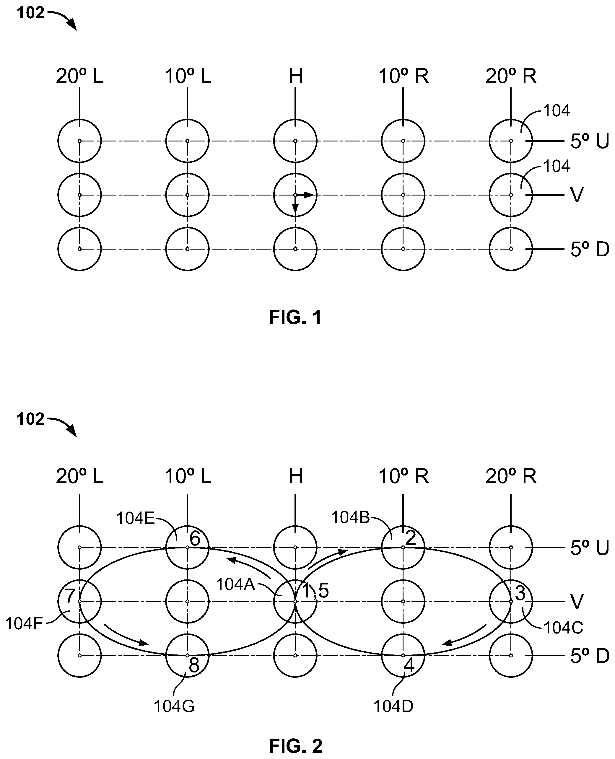
[0005] FIG. 1 is an example array of light spots in the far field.
[0006] FIG. 2 is an example sequence of illumination of the array of light spots in FIG. 1 to create a figure "8" light pattern.
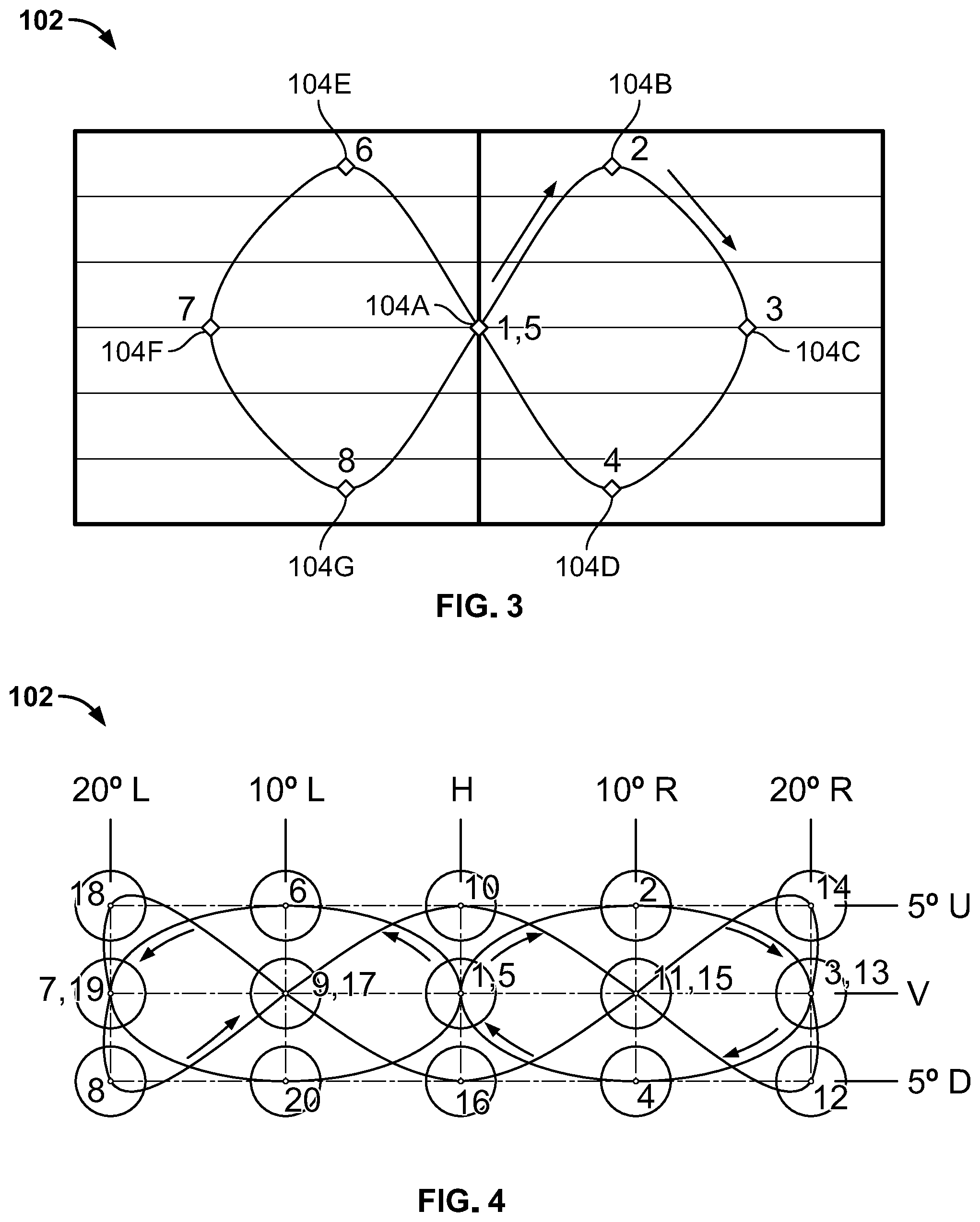
[0007] FIG. 3 is an example figure "8" light pattern as produced by the sequence of illumination of FIG. 2.
[0008] FIG. 4 is an example sequence of illumination of the array of light spots in FIG. 1 to create an oscillating light pattern.
[0009] FIG. 5 is an example oscillating light pattern produced by the sequence of illumination of FIG. 4.
[0010] FIG. 6 is an example warning device including a rectangular array of light sources.
[0011] FIG. 7 is an isometric view of the rectangular array of FIG. 4 showing example prism orientations.
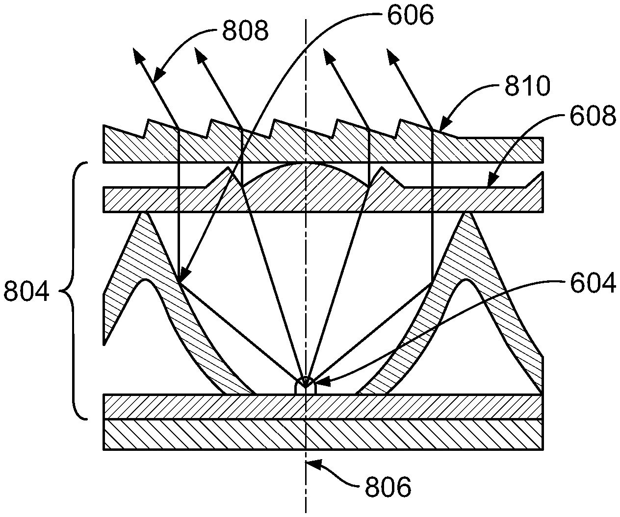
[0012] FIG. 8 is a cross section of an example cell of the rectangular array of FIG. 4.
[0013] FIG. 9 is another example warning device including a linear array of light sources.
[0014] FIG. 10 is another example warning device including two linear arrays of light sources.
[0015] FIG. 11 is an example array of light spots in the far field from the warning device of FIG. 10.
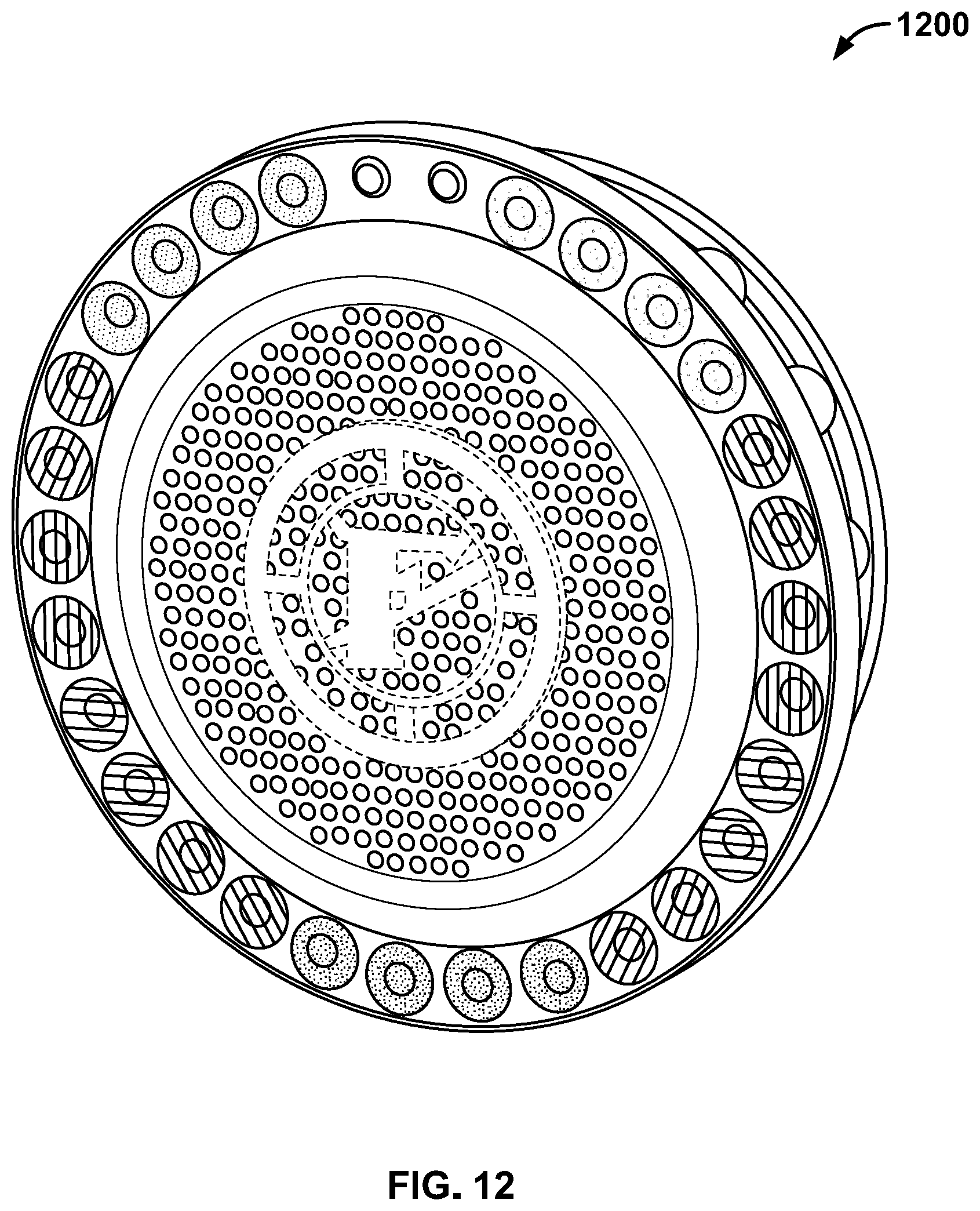
[0016] FIG. 12 is another example warning device including a circular array of light sources.
[0017] FIG. 13 is an exploded view of the warning device of FIG. 12.
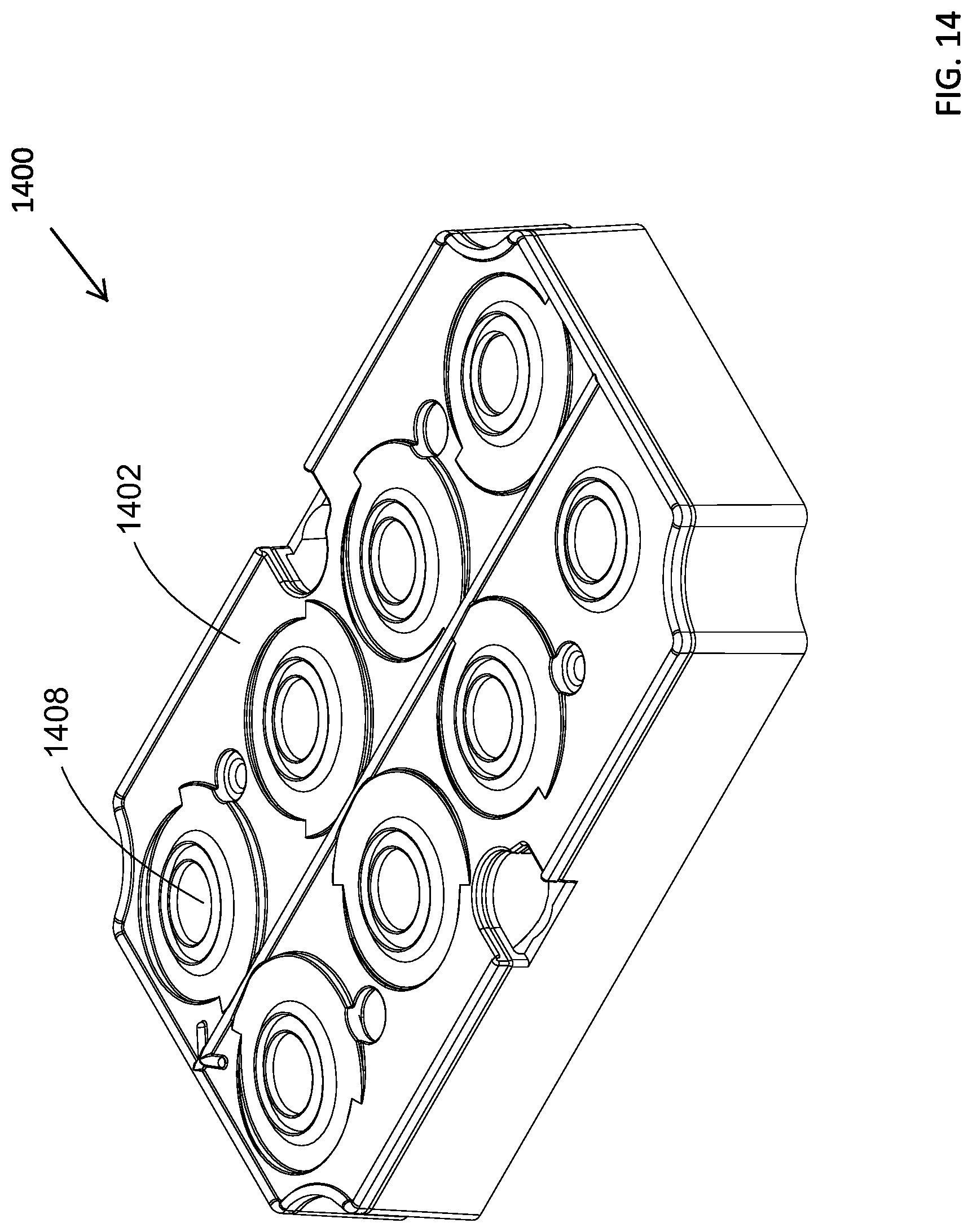
[0018] FIG. 14 is another example warning device with a principal axis of the reflector and lens system being tilted.
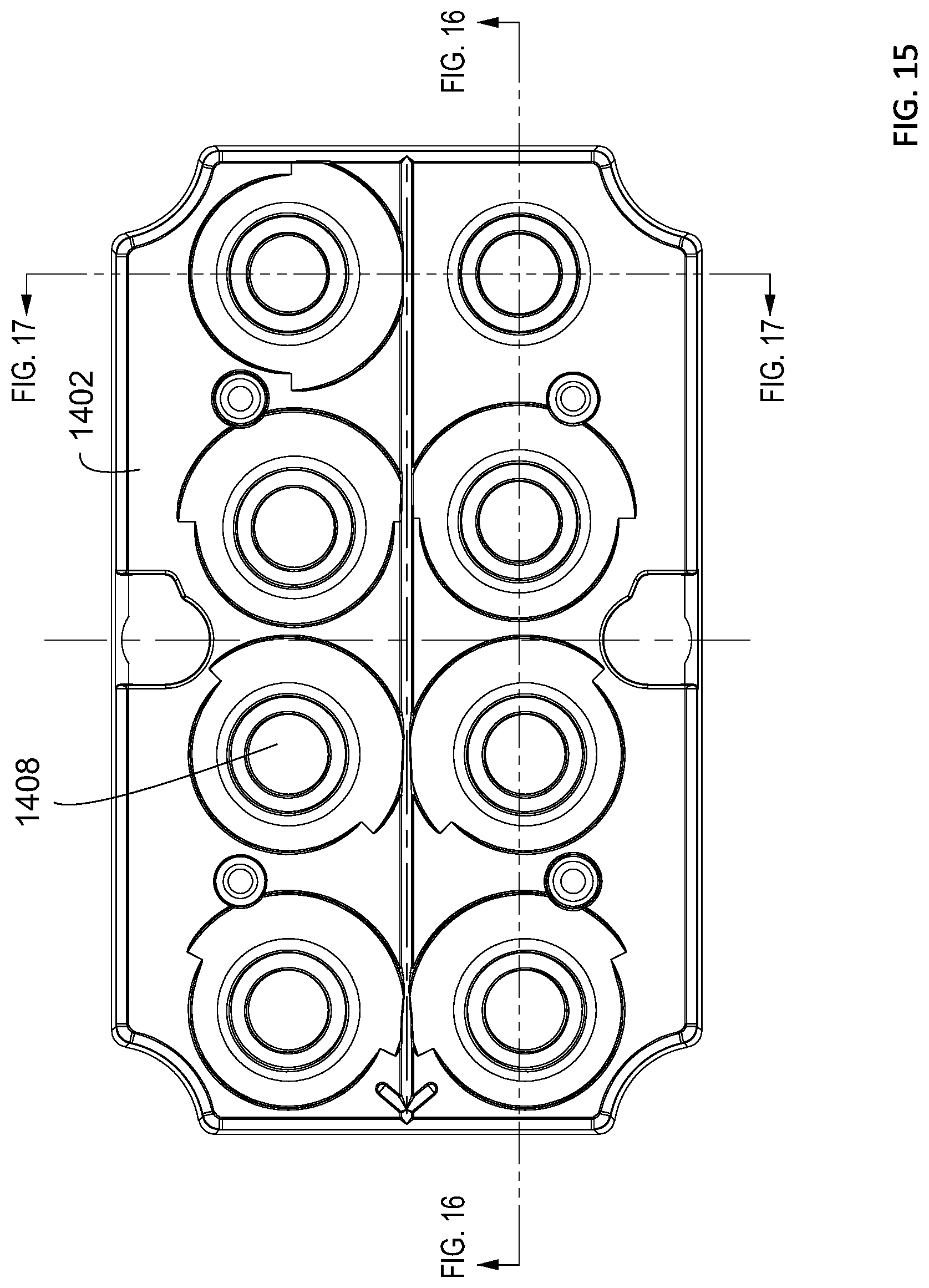
[0019] FIG. 15 is a top view of the warning device of FIG. 14.
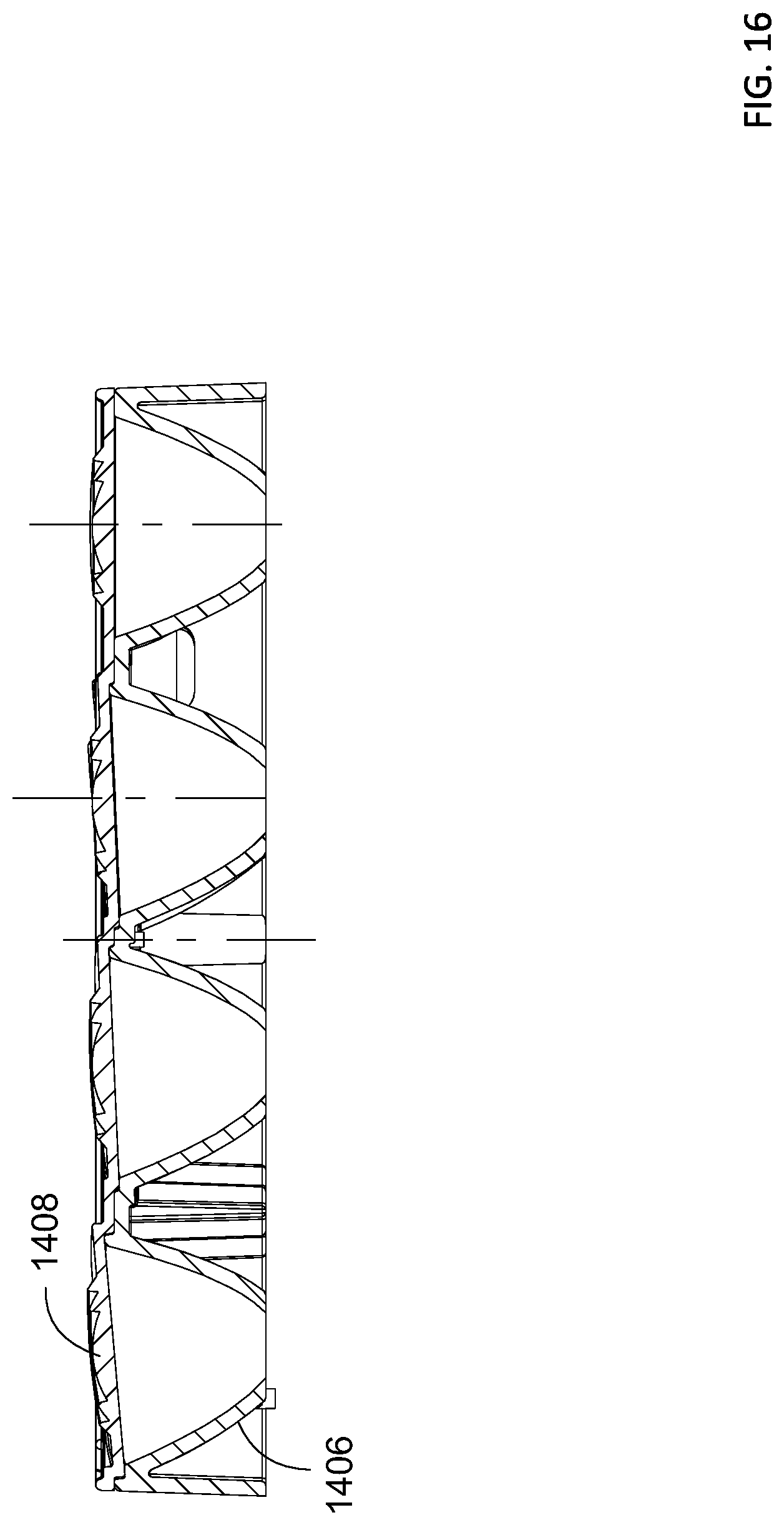
[0020] FIG. 16 is a cross section of example cells of the warning device of FIG. 14.
[0021] FIG. 17 is another cross section of example cells of the warning device of FIG. 14.
[0022] FIG. 18 is a schematic view of the principal axes of the light source and the lens of the cells of the warning device of FIG. 14.
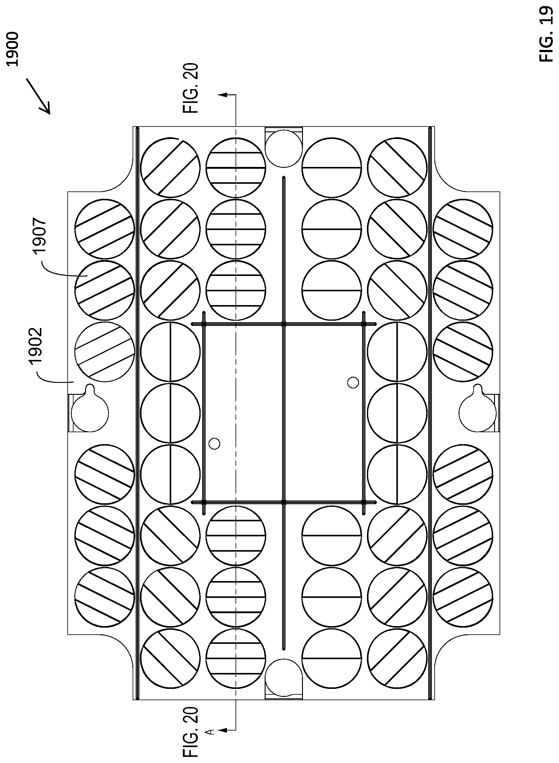
[0023] FIG. 19 is another example warning device with the lens and prism plates being combined into a single, integral body.
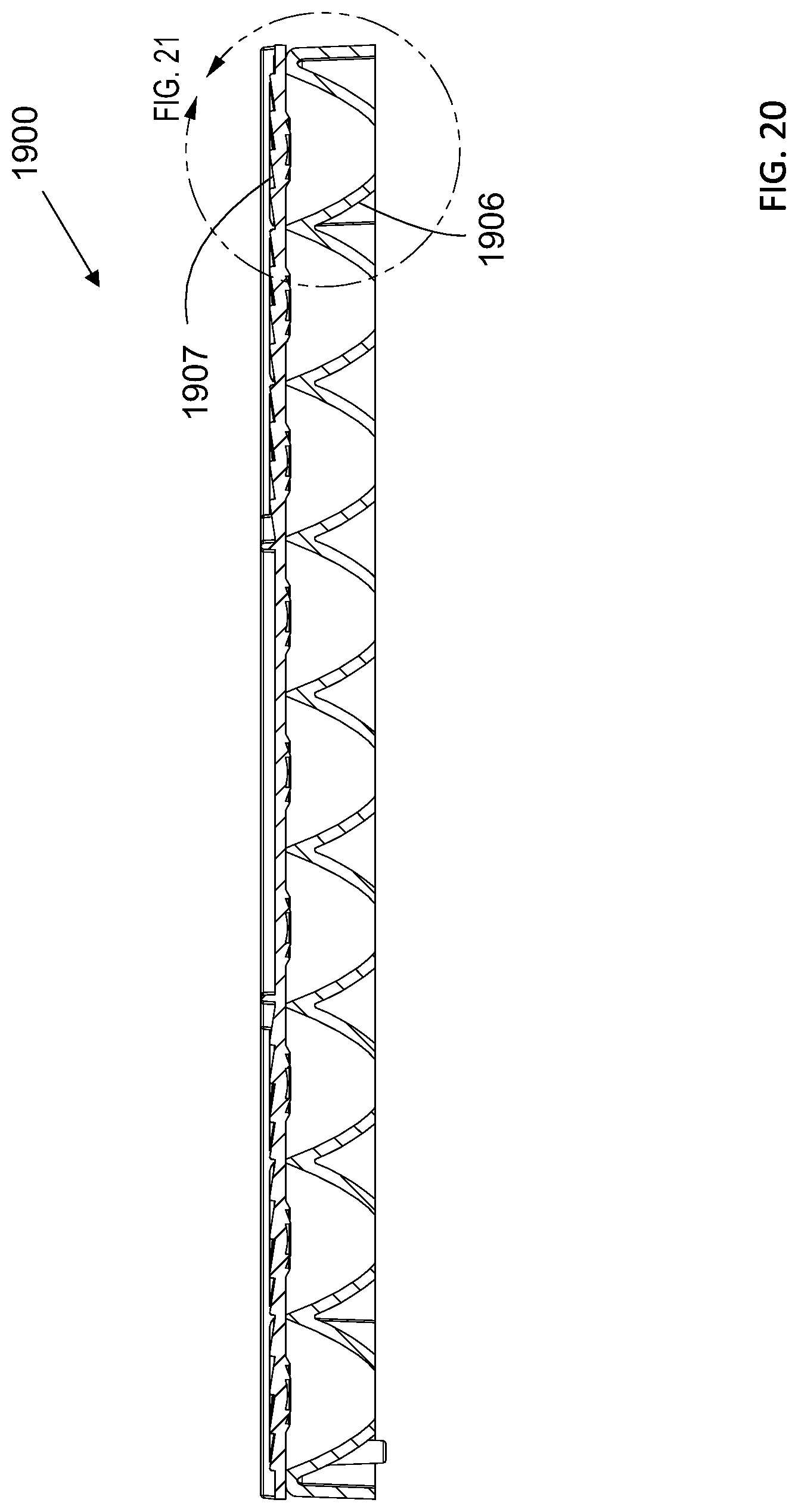
[0024] FIG. 20 is a cross section of example cells of the warning device of FIG. 19.
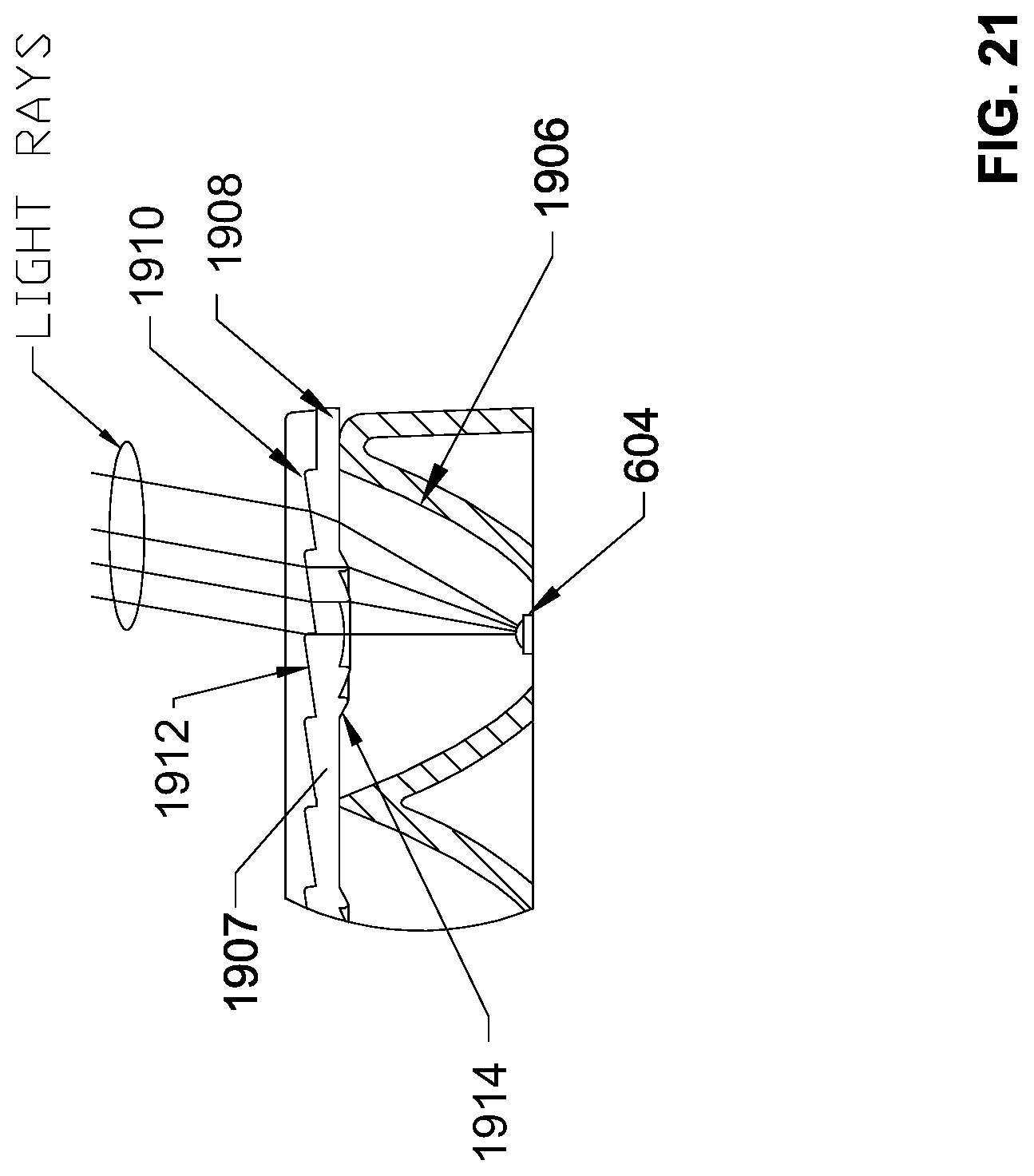
[0025] FIG. 21 is an enlarged view of one of the cells of the example cells of FIG. 20.
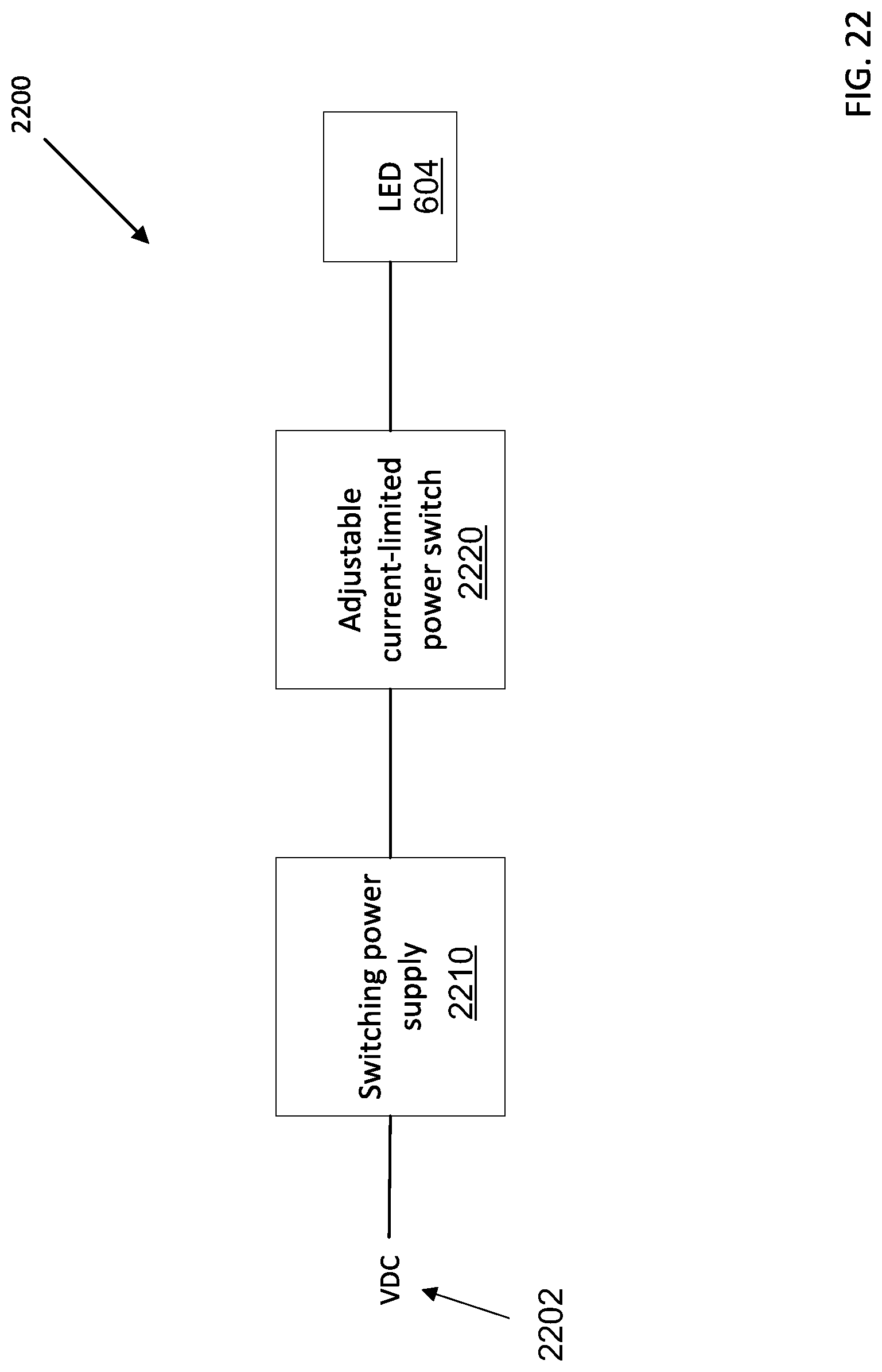
[0026] FIG. 22 is an example drive system for a warning device.
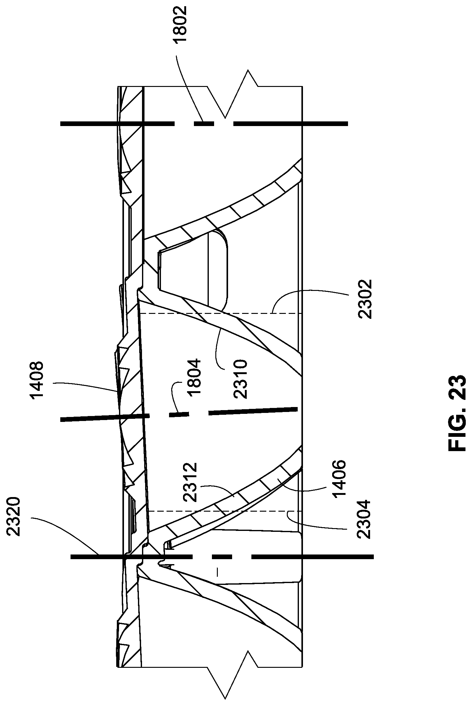
[0027] FIG. 23 is an enlarged view of the cross section of the warning device of FIG. 14.
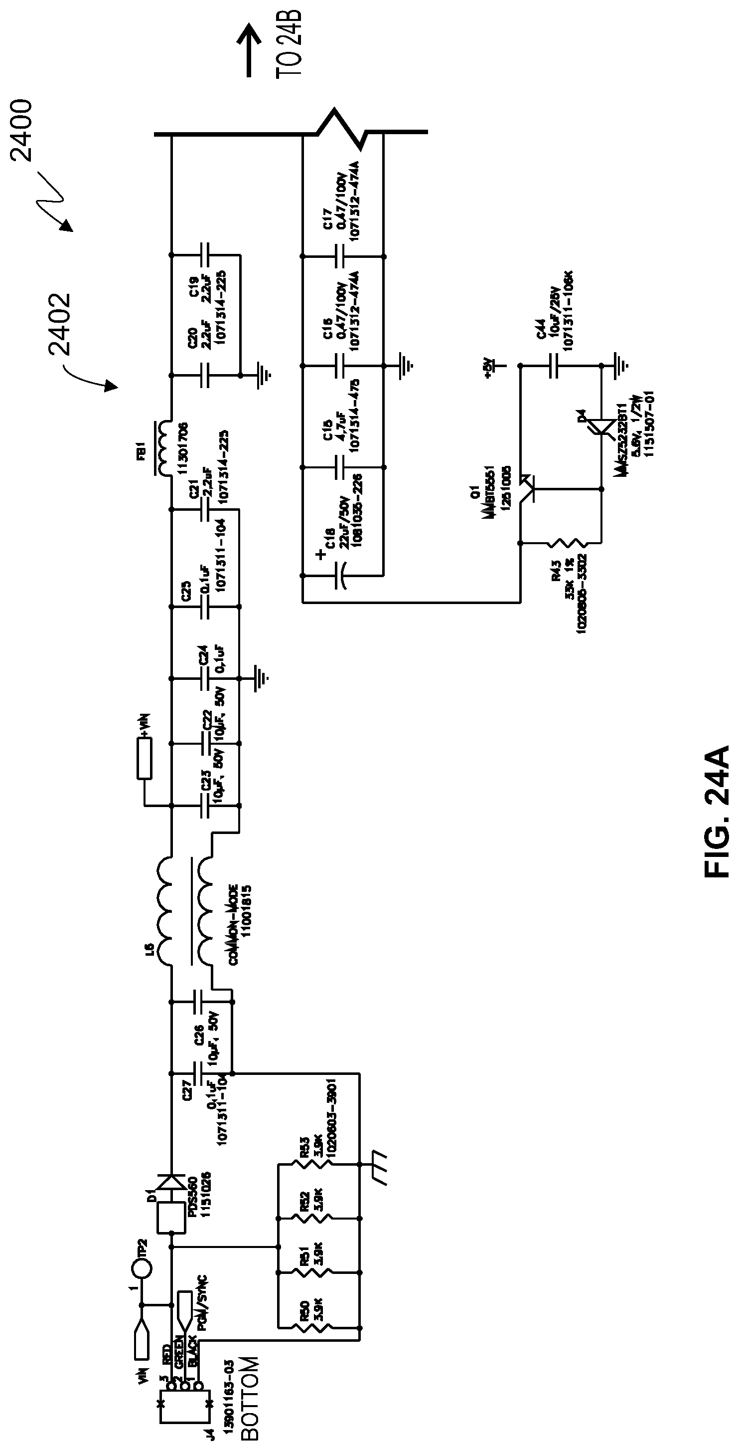
[0028] FIG. 24A is a schematic diagram of a portion of example circuitry that can be used for the drive system of FIG. 22.
[0029] FIG. 24B is a schematic diagram of a further portion of example circuitry that can be used for the drive system of FIG. 22.
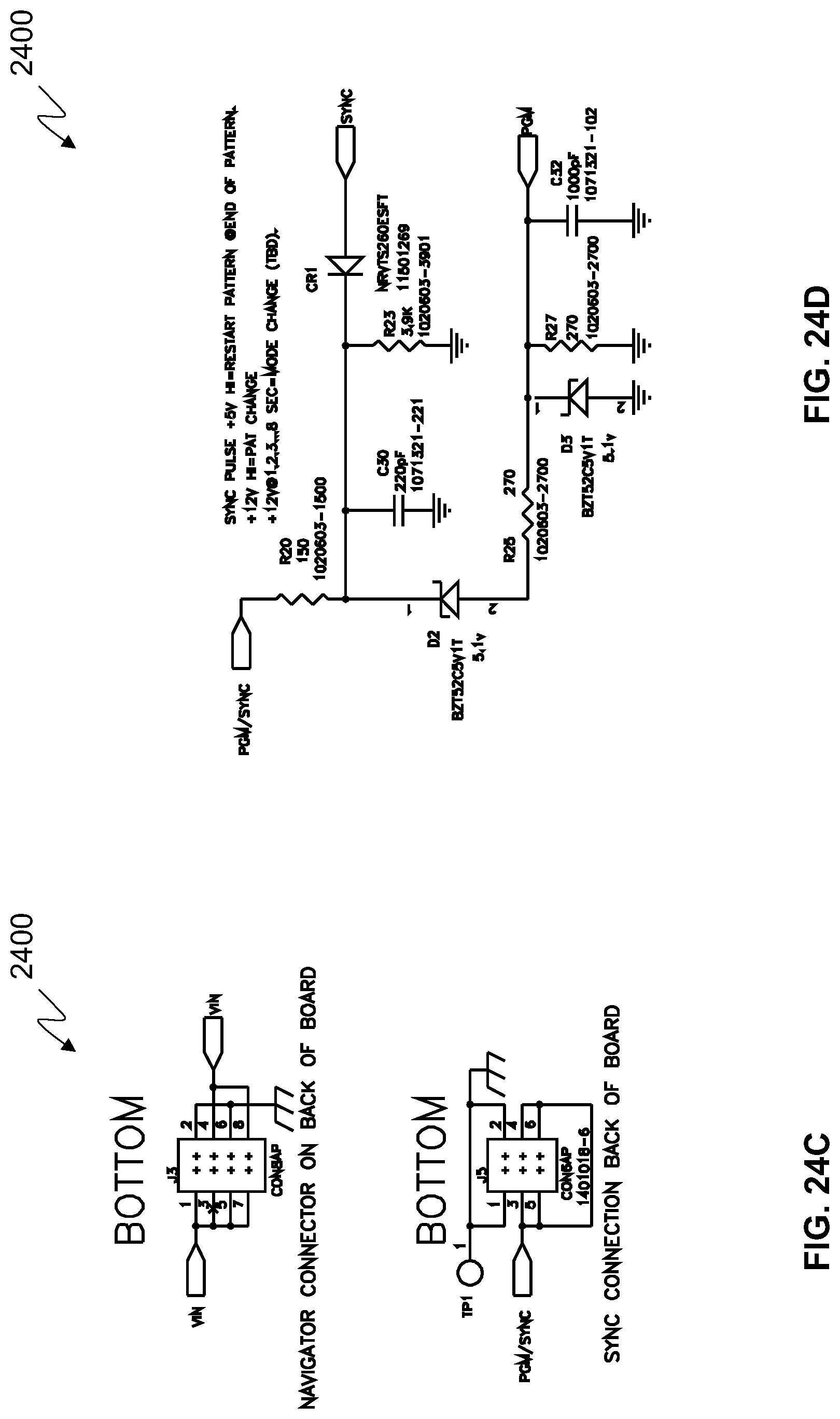
[0030] FIG. 24C is a schematic diagram of a further portion of example circuitry that can be used for the drive system of FIG. 22.
[0031] FIG. 24D is a schematic diagram of a further portion of example circuitry that can be used for the drive system of FIG. 22.
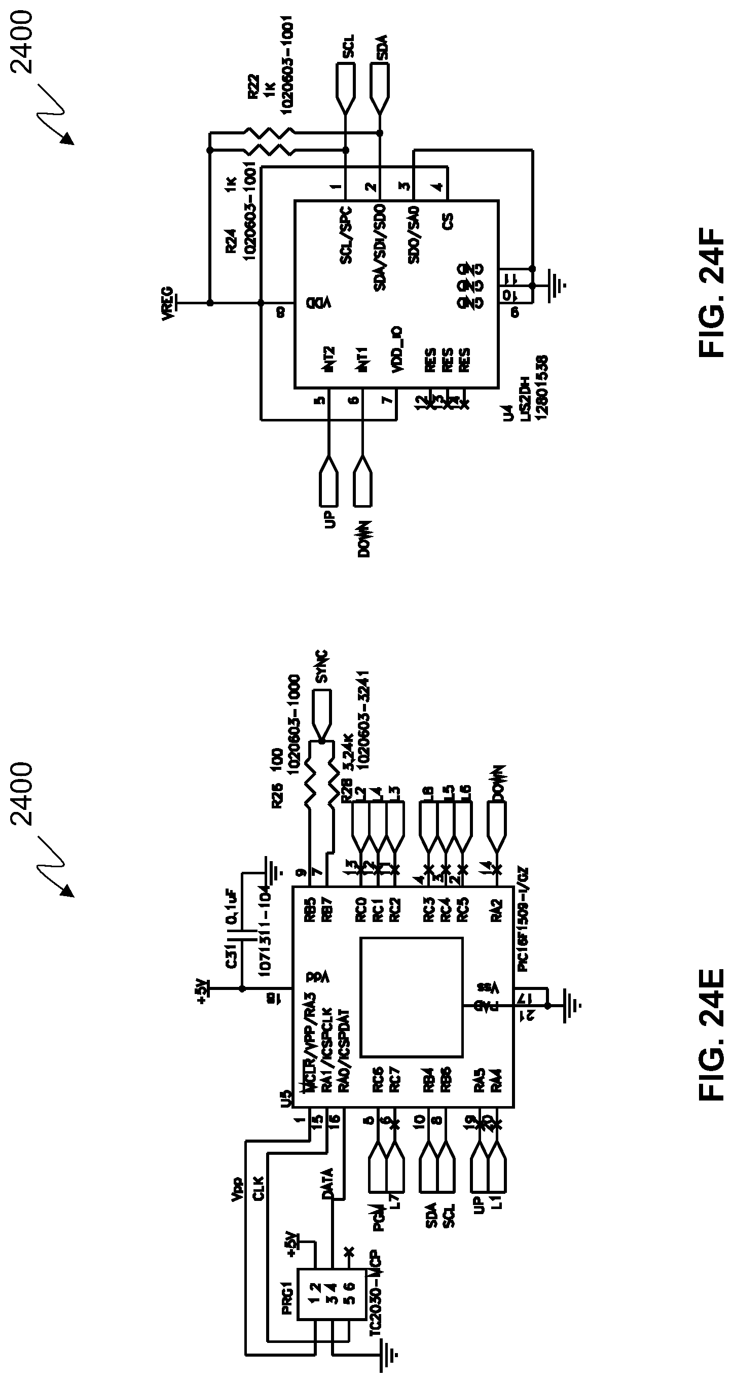
[0032] FIG. 24E is a schematic diagram of a further portion of example circuitry that can be used for the drive system of FIG. 22.
[0033] FIG. 24F is a schematic diagram of a further portion of example circuitry that can be used for the drive system of FIG. 22.
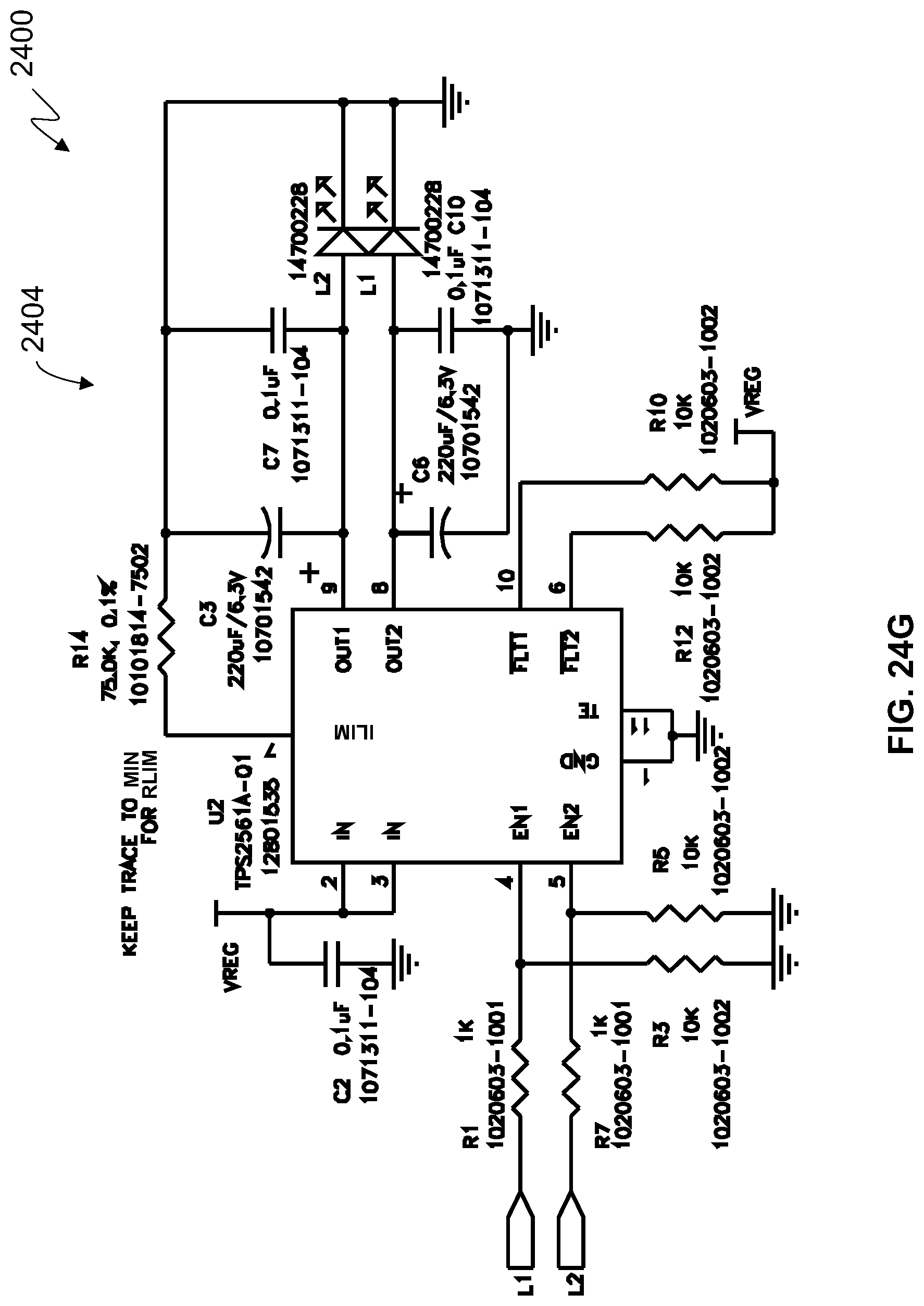
[0034] FIG. 24G is a schematic diagram of a further portion of example circuitry that can be used for the drive system of FIG. 22.
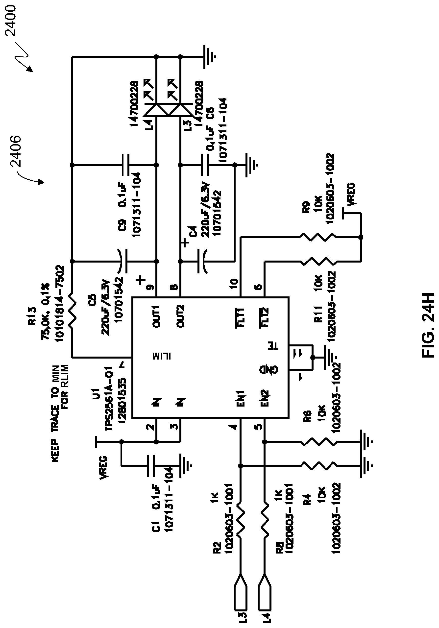
[0035] FIG. 24H is a schematic diagram of a further portion of example circuitry that can be used for the drive system of FIG. 22.
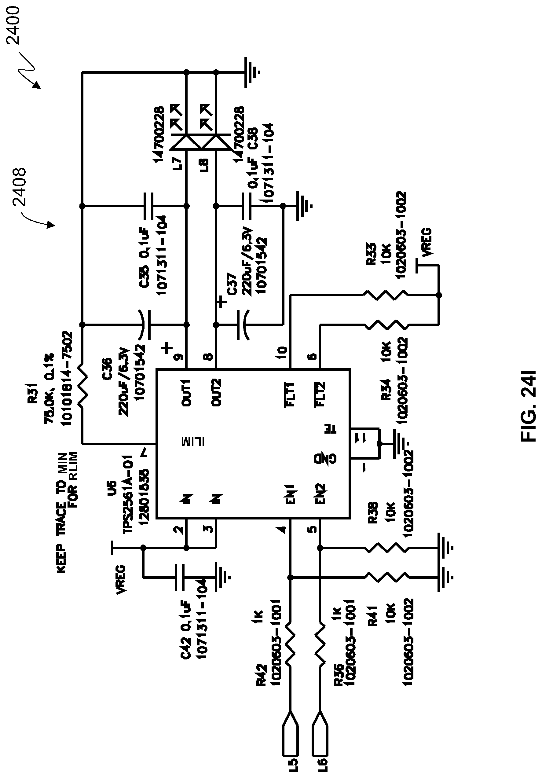
[0036] FIG. 24I is a schematic diagram of a further portion of example circuitry that can be used for the drive system of FIG. 22.
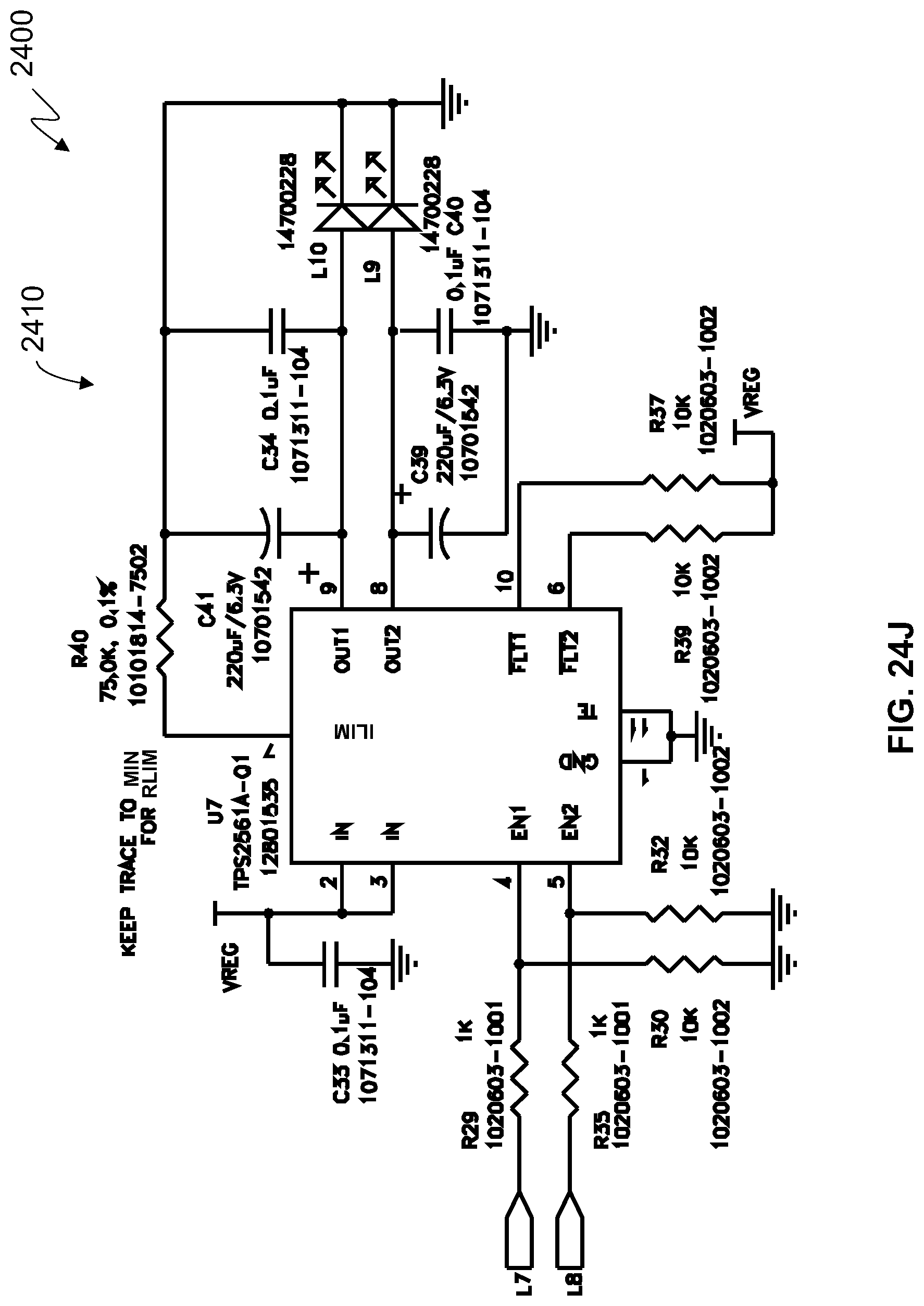
[0037] FIG. 24J is a schematic diagram of a further portion of example circuitry that can be used for the drive system of FIG. 22.
[0038] FIG. 24K is a schematic diagram of a further portion of example circuitry that can be used for the drive system of FIG. 22.
[0039] FIG. 24L is a schematic diagram of a further portion of example circuitry that can be used for the drive system of FIG. 22.
[0040] FIG. 24M is a schematic diagram of a further portion of example circuitry that can be used for the drive system of FIG. 22.
[0041] FIG. 24N is a schematic diagram of a further portion of example circuitry that can be used for the drive system of FIG. 22.
DETAILED DESCRIPTION
[0042] The present disclosure is directed to warning devices, such as those used on emergency vehicles, that create various light patterns without using mechanical mechanisms to do so.
[0043] In such examples, the warning device(s) can be typically located on the front of an emergency vehicle and produce the far field light spot pattern perpendicular to the direction of vehicle motion. In such an example, the 3 on-axis far field light spots (located on the H axis depicted in FIG. 1) would be in line with preceding vehicles in the lane in which the emergency vehicle is traveling. They would provide a warning signal to these vehicles (through their rear view mirrors) that an emergency vehicle calling for the right of way was behind them. The other far field light spots (located on the axes 20.degree. L, 10.degree. L, 10.degree. R, and 20.degree. R depicted in FIG. 1) would align with the vehicles in adjacent lanes of traffic and would provide a warning signal to these vehicles that an emergency vehicle was calling for the right of way. The intersection of each far field light spot and vehicle would depend on each vehicle's distance from the emergency vehicle and the distance between the lanes.
[0044] Embodiments described herein utilize light sources (such as light-emitting diodes (LEDs)), secondary optics, and control electronics to produce an array of light spots in the far field. The control electronics allow individual control of each light spot. Illuminating these spots in a predefined sequence allows for the creation of oscillating light patterns in the far field comparable to those produced by mechanical oscillating warning lights.
[0045] One advantage associated with these embodiments is that multiple oscillatory light patterns can be stored in memory and initiated as needed without the need for taking the warning device out of service. In this way, different oscillating patterns suitable for different circumstances can be available to the operator.
[0046] In one example, a plurality of light sources (such as Light-Emitting Diodes (LEDs)) and secondary optics are used to produce an array of light spots in the far field. In the embodiment described, an array 102 is composed of 15 spots or pixels 104, as depicted in FIG. 1. Each light spot 104 represents at least one light source, such as an LED.
[0047] The control electronics can individually control the state of each of these light spots 104, such as completely off, completely on, on with increasing intensity, on with decreasing intensity, etc. Sequencing, brightening, and dimming the state of each of these light spots 104 allows for the simulation of the far field lighting effect of an oscillating warning light.
[0048] FIGS. 2-5 illustrate some of the possible light patterns, such as a figure "8" pattern. For example, in FIGS. 2-3, a subset of 7 of the far-field spots 104A-104G are lit in the order indicated (e.g., 1, 2, 3, . . . 8) to create a figure "8" pattern in the far field. This pattern can be repeated in the order indicated: 104A, 104B, 104C, 104D, 104A, 104E, 104F, and 104G.
[0049] Likewise, in FIGS. 4-5, all 15 of the far-field spots 104 are lit in the noted order to create an oscillating pattern.
[0050] As shown in FIGS. 6-8, a warning device 600 has an optical system 602 that is composed of a rectangular array of LEDs 604. Each LED 604 is surrounded by a reflector 606 and/or lens elements 608. The combination of the reflector 606 and/or lens elements 608 collimate the light from each LED 604 and direct it along the optical axis 806 of the LED 604. This results in effectively increasing the luminous intensity of each of the LED/Reflector/Lens (LRL) cells 804. Each LRL cell 804 then passes through an optical prism plate 810, which directs the light 808 to one of the 15 far field light spots. While the prism plate 810 is depicted as a separate component, its function could be incorporated into either the reflector element 606, lens element 608, or both. See, e.g., FIGS. 9 and 21, described below.
[0051] In this embodiment, the light output of three LRL cells 804 are directed to each of the 15 far field light spots. Alternatively, either more (4, 5, etc.) or less (1 or 2) LRL cells 804 could be directed to each of the 15 far field light spots. For example, in this embodiment, the H-V pixel (i.e., the middle six lights without associated prism elements) which is directly forward of the device has 6 LRL cells directed toward it. This is distinct from the embodiment shown in FIGS. 9 and 10, which only utilize as few as 1 LRL cell per far field light spot. The embodiment depicted in FIG. 12 uses 2 LRL cells per far field light spot. The number of LRL cells per far field light spot is dependent on the available physical space and the desired intensity of the far field light spot.
[0052] A controller 613 of the warning device 600 includes control electronics that are programmed to control illumination of each LED 604 to provide a desired effect (e.g., oscillations).
[0053] The preceding description is of one embodiment. Other embodiments are possible.
[0054] For example, as depicted in FIG. 9, the dimensions of the LED array could be changed so that the warning light 900 would be suitable for mounting in a warning light bar or installed into a housing to make a stand-alone warning device. In this example, the warning light 900 includes a printed circuit board 902 with LED sources 903 positioned thereon. In this example, the LED sources 903 are grouped into threes. An array of collimating optics 904 is provided, along with an outer lens 906. In this example, the outer lens 906 includes integral prism plate optics.
[0055] A warning light 1000 that includes splitting the single array into two arrays 1010, 1020 is depicted in FIG. 10. In this embodiment, 2 instances of the same device containing an 8.times.1 array of LRL cells can be used to produce the 15 element far-field light spot array 1100 previously described and shown in FIG. 11. The first device 1010 (the right hand device shown in FIG. 10) produces the 8 far-field light spots located at the center, left of center, and upper level of the far field pattern 1100. By inverting the second device 1020, it will produce the 8 far-field light spots located at the center, right of center, and lower level of the far field pattern 1100. Splitting the warning light 1000 in this way allows two of the same part to be used to produce the far field pattern, which is a manufacturing advantage. FIGS. 10-11 depict how the LRL cells in each device 1010, 1020 are mapped into the far field 15 light spot array 1100.
[0056] Another variation of a warning device 1200 is depicted in FIGS. 12-13. In this embodiment, the LRL cells include a reflector ring 1204 and are positioned in a circular array instead of rectangular array. When configured in a circular array, the reflector ring 1204 can surround a siren 1202 (such as the Federal Signal Q-Siren) that emits an emergency sound or other type of warning device resulting in a multi-function device. In the example depicted, the reflector ring 1204 is configured with LEDs positioned about the circular array, and a lens ring 1206 and a prism plate ring 1208 are positioned to form the warning device 1200 shown in FIG. 12.
[0057] Referring now to FIGS. 14-18 and 23, another variation of a warning device 1400 having an optical system 1402 is depicted. In this example, the principal axis 1804 of the reflector 1406 and lens 1408 system (the lens 1408 is transparent let light pass therethrough) is tilted at a prescribed angle .alpha., as depicted in FIGS. 16 and 18. This results in light emanating from the device 1400 being collimated at the angle .alpha. along the tilted principal axis 1804 in both the Y and Z planes. See FIG. 18. The tilting of the reflector 1406 and lens 1408 system provides the direction of the light from the focal point 1806 of the associated light source to one of the far field light spots without requiring a prism plate. The principal axis 1804 of the reflector 1406 and the lens 1408 system is thus tilted at a nonzero angle relative to the optical axis 1802 of the associated light source.
[0058] As shown in FIG. 23, the lens 1408 is positioned outside of the reflector 1406. A first portion 2310 of the reflector 1406 extends at a first distance 2302, and a second portion 2312 of the reflector extends at a second distance 2304. The reflector 1406 and the lens 1408 system is tilted relative to the optical axis 1802 of the associated light source, such that the first distance 2302 is greater than the second distance 2304. A portion 2320 of the lens 1408 steps upward for the next reflector 1406 to accommodate the tilt and the different distances 2310 and 2312 such that each of the lenses 1408 is angled to direct light to one of the far field light spots.
[0059] Referring now to FIGS. 19-21, another variation of a warning device 1900 having an optical system 1902 is depicted. In this example, the lens features 1908 and prism plate features 1910 are combined into a single, integral body 1907 (similar to that of the outer lens 906 with the integral prism plate optics of FIG. 9). The combined lens and prism plate 1907 (which is transparent to let light pass therethrough) functions to both collimate the light and focus the light in far field light spots. In this example, the lens features 1908 are formed on an interior surface 1914 of the combined lens and prism plate 1907, and the prism plate features 1910 are formed on an outer surface 1912 of the combined integral body 1907 of lens and prism plate.
[0060] Referring now to FIG. 22, an example drive system 2200 for a warning device is shown. In this example, the drive system 2200 is a two-stage system.
[0061] The solid-state physics of high brightness LEDs 604 result in a forward voltage drop that varies slightly based on the solid-state chemistry of the particular device. The Forward Voltage (VF) is a device parameter that is controlled in binning of LEDs by the LED manufacturer and is specifiable when ordering a particular LED device. In designing High Brightness LED circuits, it can be important not to overdrive an LED Emitter. Regulating the voltage applied to the device and limiting the current going through the device optimizes optical and thermal performance of the device.
[0062] The drive system 2200 uses a switching power supply 2210 to step down the DC input voltage 2202. The output voltage of the switcher 2210 is chosen to be a voltage of a certain amount (e.g., 0.2 VDC) above the maximum VF of the LED 604 being driven. The LEDs 604 in the drive system 2200 are not being driven in strings of three LED's as in typical applications. An individual LED 604 is being driven in the drive system 2200. The output voltage of the switcher 2210 is set to a precise output through choosing precision resistors to minimize prematurely destroying or thermally degrading the device.
[0063] The voltage of the switcher 2210 is connected to an adjustable current-limited power switch 2220. In one example, the chosen adjustable current-limited power switch 2220 is a Texas Instruments TPS2561A-Q1 Dual Channel Precision Automotive Adjustable Current-Limited Power Switch. This device is intended for automotive applications where precision current limiting is required. Typical LED driver schemes measure the current going through a string of LEDs and, through feedback, regulate the current. These switches are designed to be very precise by using a 0.1 percent resistor and limit the current going to a load. A sharp current limit is set through the power switch 2220, allowing for a maximum current flow through the device.
[0064] FIGS. 24A through 24N show schematic diagrams of portions 2400 of example circuitry that can be used for the drive system 2200 of FIG. 22. Referring to FIGS. 24A through 24N, the circuitry portion 2402 can correspond to the switching power supply 2210 of FIG. 22, and the circuitry portions 2404, 2406, 2408, and 2410 represent each of four dual channel USB adjustable current-limited power switches that can correspond to the adjustable current-limited power switch 2220 of FIG. 22.
[0065] The two-step approach of setting the output voltage of the switcher 2210 just above the forward voltage of the LED followed by limiting the maximum current going to the emitter results in an advantageous drive circuit for a single LED. The ability to drive an individual LED emitter, thermally and electrically efficiently, while staying in the safe operating area of the LED, allows for the ability to do unique lighting, such as the flashing of individual emitters.
[0066] In the examples provided herein, the warning devices are computing devices. The computing device can include a controller having at least one central processing unit ("CPU"), a system memory, and a system bus that couples the system memory to the CPU. The system memory includes a random access memory ("RAM") and a read-only memory ("ROM"). The computing devices can further include a mass storage device. The mass storage device is able to store software instructions and data. One or more of these memories can be used to store one or more oscillating light patterns.
[0067] The mass storage device and its associated computer-readable data storage media provide non-volatile, non-transitory storage for the computing devices. Although the description of computer-readable data storage media contained herein refers to a mass storage device, such as a hard disk or solid state disk, it should be appreciated by those skilled in the art that computer-readable data storage media can be any available non-transitory, physical device or article of manufacture from which the central processing unit can read data and/or instructions.
[0068] Computer-readable data storage media include volatile and non-volatile, removable and non-removable media implemented in any method or technology for storage of information such as computer-readable software instructions, data structures, program modules or other data. Example types of computer-readable data storage media include, but are not limited to, RAM, ROM, EPROM, EEPROM, flash memory or other solid state memory technology, CD-ROMs, digital versatile discs ("DVDs"), other optical storage media, magnetic cassettes, magnetic tape, magnetic disk storage or other magnetic storage devices, or any other medium which can be used to store the desired information and which can be accessed by the computing devices.
[0069] According to various embodiments, the warning device may operate in a networked environment using logical connections to remote network devices through a network, such as a wireless network, the Internet, or another type of network. The computing devices may also include an input/output controller for receiving and processing input from a number of other devices, including a touch user interface display screen, or another type of input device. Similarly, the input/output controller may provide output to a touch user interface display screen or other type of output device.
[0070] As mentioned, the mass storage device and the RAM of the computing devices can store software instructions and data. The software instructions include an operating system suitable for controlling the operation of the computing devices. The mass storage device and/or the RAM also store software instructions, that when executed by the CPU, cause the computing devices to provide the functionality of the controller discussed in this document.
[0071] Although various embodiments are described herein, those of ordinary skill in the art will understand that many modifications may be made thereto within the scope of the present disclosure. Accordingly, it is not intended that the scope of the disclosure in any way be limited by the examples provided.
* * * * *
D00000
D00001
D00002
D00003
D00004
D00005
D00006
D00007
D00008
D00009
D00010
D00011
D00012

D00013
D00014
D00015
D00016
D00017
D00018
D00019

D00020
D00021
D00022
D00023
D00024
D00025
D00026

XML
uspto.report is an independent third-party trademark research tool that is not affiliated, endorsed, or sponsored by the United States Patent and Trademark Office (USPTO) or any other governmental organization. The information provided by uspto.report is based on publicly available data at the time of writing and is intended for informational purposes only.
While we strive to provide accurate and up-to-date information, we do not guarantee the accuracy, completeness, reliability, or suitability of the information displayed on this site. The use of this site is at your own risk. Any reliance you place on such information is therefore strictly at your own risk.
All official trademark data, including owner information, should be verified by visiting the official USPTO website at www.uspto.gov. This site is not intended to replace professional legal advice and should not be used as a substitute for consulting with a legal professional who is knowledgeable about trademark law.