Internal Combustion Engine
SPYRA; Nikolaus ; et al.
U.S. patent application number 16/369596 was filed with the patent office on 2020-10-01 for internal combustion engine. The applicant listed for this patent is Innio Jenbacher GmbH & Co OG. Invention is credited to Francisco LOPEZ, Nikolaus SPYRA, Lukas UNDEVALL.
| Application Number | 20200309047 16/369596 |
| Document ID | / |
| Family ID | 1000004048681 |
| Filed Date | 2020-10-01 |
| United States Patent Application | 20200309047 |
| Kind Code | A1 |
| SPYRA; Nikolaus ; et al. | October 1, 2020 |
INTERNAL COMBUSTION ENGINE
Abstract
Internal combustion engine (10) with: at least one turbocharger which has a compressor (1) and an exhaust turbine (2), and which can be stably operated in a stable operating range of a compressor map of the at least one compressor (1), which stable operating range is limited by a surge line (P) on the one hand, and by a choke line (S) on the other hand at least one actuator for setting an operating point (4) of the at least one compressor (1) in the compressor map a measuring device (5) for measuring at least two operating parameters of the turbocharger, by means of which a position of an operating point (4) of the at least one compressor (1) is determinable in the compressor map a closed loop or open loop control device (6) which is connected to the measuring device (5), and is designed to activate the at least one actuator whereby the closed loop or open loop control device (6) is designed in a way to regulate or control the at least one actuator in such a way that reaching the surge line (P) by the operating point (4) of the at least one compressor (1) is prevented.
| Inventors: | SPYRA; Nikolaus; (Jenbach - 7 Tirol, AT) ; UNDEVALL; Lukas; (Jenbach - 7 Tirol, AT) ; LOPEZ; Francisco; (Jenbach, AT) | ||||||||||
| Applicant: |
|
||||||||||
|---|---|---|---|---|---|---|---|---|---|---|---|
| Family ID: | 1000004048681 | ||||||||||
| Appl. No.: | 16/369596 | ||||||||||
| Filed: | March 29, 2019 |
| Current U.S. Class: | 1/1 |
| Current CPC Class: | F02B 39/10 20130101; F02B 37/16 20130101; F05D 2220/40 20130101; F02D 41/0007 20130101 |
| International Class: | F02D 41/00 20060101 F02D041/00; F02B 39/10 20060101 F02B039/10 |
Claims
1. An internal combustion engine with: at least one turbocharger which has a compressor and an exhaust turbine, and which can be stably operated in a stable operating range of a compressor map of the at least one compressor, which stable operating range is limited by a surge line on the one hand, and by a choke line on the other hand at least one actuator for setting an operating point of the at least one compressor in the compressor map a measuring device for measuring at least two operating parameters of the turbocharger, by means of which a position of an operating point of the at least one compressor is determinable in the compressor map a closed loop or open loop control device which is connected to the measuring device, and is designed to activate the at least one actuator wherein the closed loop or open loop control device is designed in a way to regulate or control the at least one actuator in such a way that reaching the surge line by the operating point of the at least one compressor is prevented.
2. The internal combustion engine according to claim 1, wherein the at least two operating parameters of the turbocharger are selected from: pressure ratio across the compressor volume flow or mass flow through the compressor rotational speed of the turbocharger or parameters derived from these parameters.
3. The internal combustion engine according to claim 1, wherein the at least one actuator is designed as a bypass valve, wastegate, variable valve train, throttle valve, inlet valve for air or mixture downstream of the compressor, as variable turbine geometry, actuator for influencing the point of time of the ignition or for the shutdown of ignition devices for the combustion chambers, or as an actuator for influencing the quantity or point of time of injecting liquid or gaseous fuel in the combustion chambers.
4. The internal combustion engine according to claim 1, wherein the closed loop or open loop control device is designed so as to prevent reaching the surge line by the operating point when the operating point moves caused by external influences.
5. The internal combustion engine according to claim 4, wherein a signalling device is provided, which is connected to or connectable to an energy supply net, and is designed to transmit a signal to the closed loop or open loop control device when a net fault of the energy supply net is detected, wherein the closed loop or open loop control device is designed, upon receiving such a signal, to activate the at least one actuator in such a way that reaching the surge line by the operating point caused by measures of the closed loop or open loop control device, which serve to handle the net fault, is prevented.
6. The internal combustion engine according to claim 1, wherein the closed loop or open loop control device is designed to prevent the surge line from being reached by the operating point when the operating point moves caused by an internal influence.
7. The internal combustion engine according to claim 1, wherein the closed loop or open loop control device is designed to prevent the surge line from being reached by the operating point when the operating point moves caused by ageing of the compressor.
8. The internal combustion engine according to claim 1, wherein the closed loop or open loop control device is designed to cause the operating point to move along a predetermined path in the compressor map via the at least one actuator.
9. The internal combustion engine according to claim 8, wherein the closed loop or open loop control device is designed to cause the operating point to move along a predetermined path in the compressor map at least approximately parallel to the surge line via the at least one actuator.
10. The internal combustion engine according to claim 8, wherein the closed loop or open loop control device is designed to cause the operating point to move along a predetermined path within a corridor, which, preferably over a safety zone, is located in front of the surge line via the at least one actuator.
11. The internal combustion engine according to claim 1, wherein the closed loop or open loop control device is designed to calculate the activation of the at least one actuator in dependence on a compressor model.
12. The internal combustion engine according to claim 1, wherein the closed loop or open loop control device is designed to activate the at least one actuator in dependence on a pre-defined table.
13. Genset comprising a generator and an internal combustion engine mechanically coupled to the generator according to claim 1.
Description
[0001] The present invention concerns an internal combustion engine with the features of the preamble of claim 1, and a genset comprising such an internal combustion engine.
[0002] Turbochargers have long been used to compress air, a fuel-air mixture or pure fuel to a higher pressure level before being fed to the combustion chambers of the internal combustion engine.
[0003] The surge line of the compressor of the turbocharger indicates that limit at which, in the event of exceeding it, an unstable operation, e.g. a flow reversal, occurs through the compressor.
[0004] The choke line of the compressor of the turbocharger indicates that limit at which there is no mass flow through the compressor in case of reaching the limit.
[0005] External and internal influences can lead to the position of the operating point of the compressor changing, and even to the surge line being reached or exceeded. Aging of the turbocharger can also lead to such a behaviour.
[0006] If the internal combustion engine is coupled with a generator to a genset, an important example of an external influence is a net fault in a power supply net connected to the genset. This can be for example a short circuit in at least one phase of the power supply net. This leads to an undervoltage and an overcurrent, which causes strong and rapid load changes with respect to the genset. Various national legal systems stipulate that the genset must remain connected to the energy supply net at least for a certain time in the event of a net ("low voltage ride through"--LVRT). Without protective measures, there may be disadvantageous effects on the genset.
[0007] Examples of internal influences are a damage at the turbocharger, misfiring with respect to at least one combustion chamber of the internal combustion engine, etc.
[0008] The object of the invention is to provide an internal combustion engine, which allows, even in case of influences, which, in the state of the art, cause the surge line of the compressor to be reached or exceeded, a stable operation of the turbocharger, and a genset with such an internal combustion engine.
[0009] This object is solved by an internal combustion engine with the features of claim 1, and a genset with such an internal combustion engine. Advantageous embodiments of the invention are defined in the dependent claims.
[0010] As the closed loop or open loop control device is designed to regulate or control the at least one actuator in such a way that reaching the surge line is prevented by the operating point of the at least one compressor, stable operation of the turbocharger is possible even in case of negative external or internal influences.
[0011] The closed loop or open loop control device may, for example, be a central closed loop or open loop control device of the internal combustion engine.
[0012] Naturally, the possible positions of the operating point in the compressor map are limited by the maximum mechanical limits of the turbocharger.
[0013] It is preferably provided that the at least two operating parameters of the turbocharger, which are measured by the measuring device, are selected as follows: [0014] pressure ratio across the compressor [0015] volume flow or mass flow through the compressor [0016] rotation speed of the turbocharger
[0017] or parameters derived from these parameters.
[0018] It is preferably provided that at least one actuator is designed as a bypass valve, wastegate, variable valve train, throttle valve, inlet valve for air or a mixture after the compressor, as a variable turbine geometry, as an actuator for influencing the point of time of ignition, or for the shutdown of ignition devices for the combustion chambers, or as an actuator for influencing the quantity or point of time of injecting liquid or gaseous fuel into the combustion chambers.
[0019] It is preferably provided that the closed loop or open loop control device is designed in such a way that, if the operating point moves caused by external influences, reaching the surge line by the operating point is prevented.
[0020] For this, a signalling device may be provided, which is connectable to a power supply net, and is designed to send a signal to the closed loop or open loop control device when a net fault of the power supply net is detected, whereby the closed loop or open loop control device is designed in such a way that, when such a signal is received, an activation of the at least one actuator is to be carried out as to prevent the operating point from reaching the surge line due to measures taken by the closed loop or open loop control device which serve to handle the net fault (in general: reduction of the output of the internal combustion engine, e.g. suspension of ignition or setting the ignition to "late").
[0021] This bears a number of advantages: [0022] The probability of reaching or exceeding the surge line during the LVRT is reduced. [0023] The negative effects of a net fault during an LVRT regarding the turbocharger are reduced. [0024] Longer durations of the LVRT are possible. [0025] During the LVRT there is a lower power loss of the internal combustion engine as the functionality of the turbocharger is less impaired. [0026] Generators with a lower moment of inertia than previously possible can be used.
[0027] It is preferably provided that the closed loop or open loop control device is designed to prevent the surge line being reached by the operating point if the operating point moves caused by an internal influence (e.g. damage at the turbocharger, misfire with respect to at least one combustion chamber of the internal combustion engine).
[0028] It is preferably provided that the closed loop or open loop control device is designed to prevent the surge line being reached by the operating point if the operating point moves caused by ageing of the compressor.
[0029] It is preferably provided that the closed loop or open loop control device is designed to cause the operating point to move along a predetermined path in the compressor map via the at least one actuator.
[0030] It may thereby be provided that the closed loop or open loop control device is designed to cause the operating point to move along a predetermined path in the compressor map at least approximately parallel to the surge line via the at least one actuator. The closer the operating point remains to the surge line, the lower is the drop in output of the turbocharger, and thus of the internal combustion engine, because the boost pressure of the air, the fuel-air mixture or the pure fuel (depending on the design of the internal combustion engine, e.g. gas engine with mixture charging, gas engine with port injection, internal combustion engine with injection of liquid fuel, dual-fuel internal combustion engine) drops less strongly.
[0031] It may be provided that the closed loop or open loop control device is designed to cause the operating point to move along a predetermined path within a corridor arranged in front of the surge line, preferably over a safety zone, via at least one actuator.
[0032] It is preferably provided that the closed loop or open loop control device is designed to calculate the activation of the at least one actuator in dependence on a compressor model.
[0033] The way of calculation is taught, for example, in the following text books: [0034] Hermann Hiereth, Peter Prenninger, Aufladung der Verbrennungskraftmaschine--Der Fahrzeugantrieb/chapter 5, 2003, published by Springer/Vienna [0035] Gunther P. Merker, Rudiger Teichmann, Grundlagen Verbrennungsmotoren (Funktionsweise--Simulation--Messtechnik)/chapter 5 (Aufladesysteme), 7th, completely revised edition, 2014, published by Springer/Vienna [0036] Gunther P. Merker, Christian Schwarz, Grundlagen Verbrennungsmotoren (Simulation der Gemischbildung, Verbrennung, Schadstoffbildung and Aufladung)/chapter 8 (Aufladung von Verbrennungsmotoren) 4th, revised and updated edition Vieweg+Teubner, GVW Fachverlage GmbH, Wiesbaden 2009
[0037] It is preferably provided that the closed loop or open loop control device is designed to activate the at least one actuator depending on a pre-defined table. The table can be based on empirical values or created on a test stand.
[0038] The invention can preferably be used with a stationary internal combustion engine, for marine applications or mobile applications, such as so-called "non-road mobile machinery" (NRMM), preferably in each case designed as a reciprocating piston engine. The internal combustion engine can serve as a mechanical drive, e.g. for operating compressor systems, or can be coupled with a generator to form a genset for generating electrical power. The internal combustion engine preferably has a large number of combustion chambers.
[0039] Embodiments of the invention are discussed using the figures. They show:
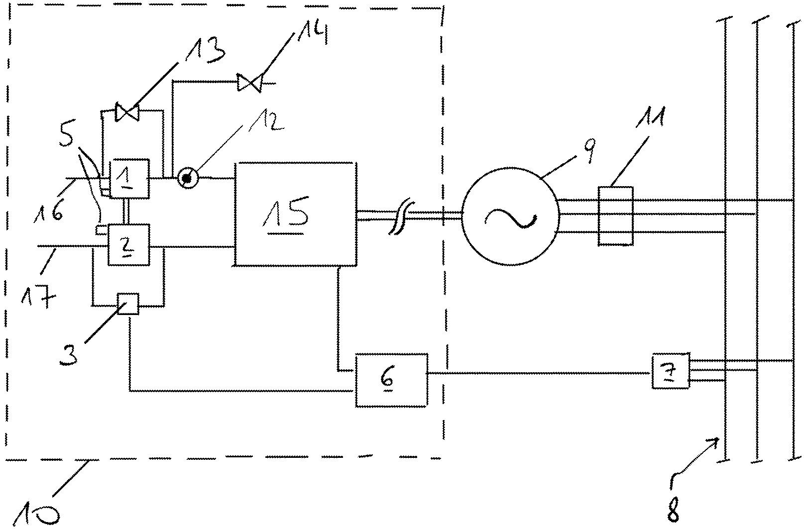
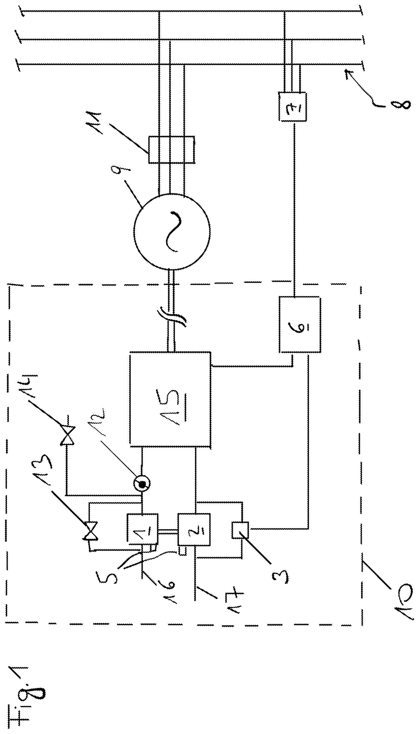
[0040] FIG. 1 a schematic illustration of an internal combustion engine according to the invention
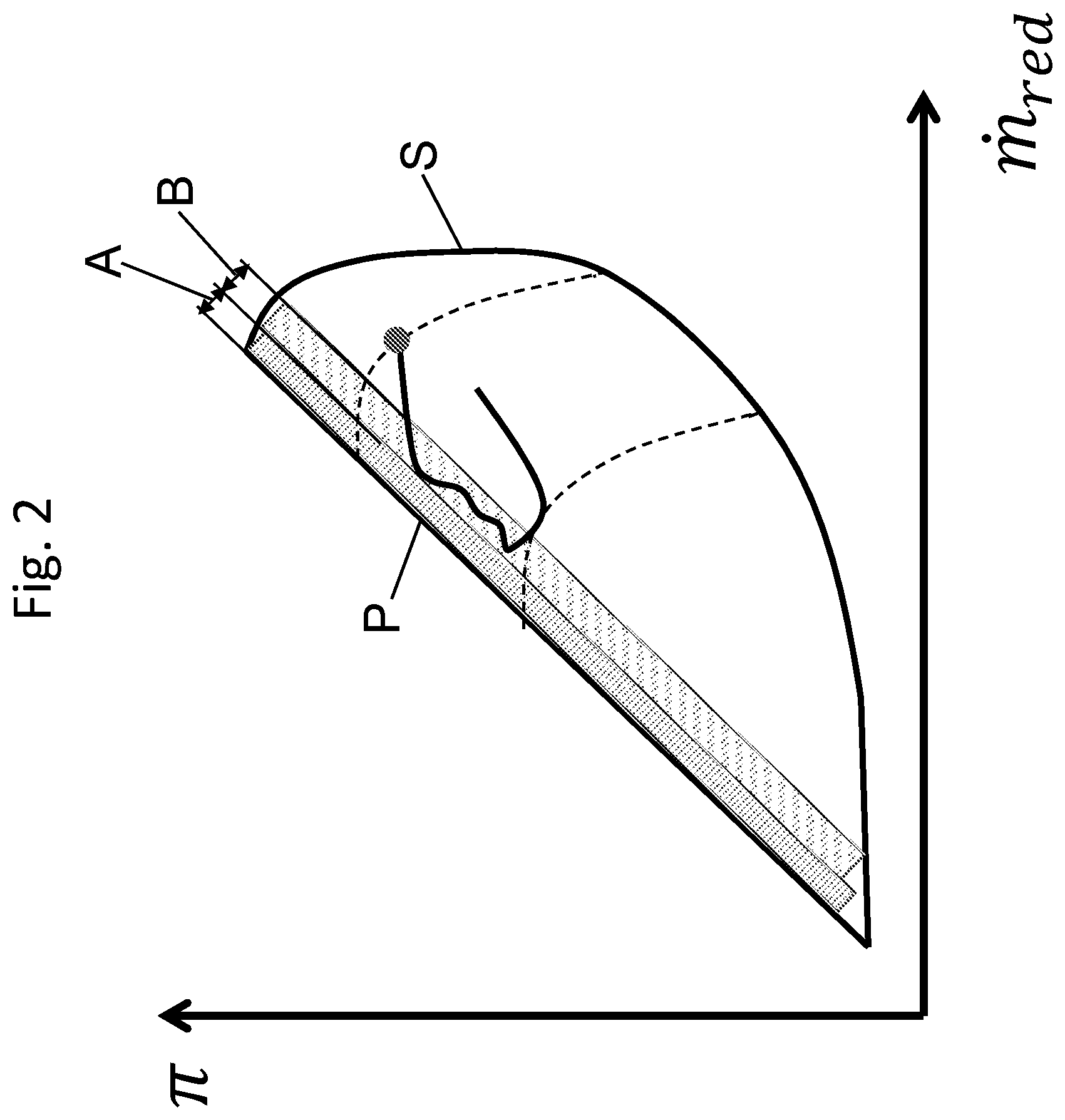
[0041] FIG. 2 a compressor map of a turbocharger of an internal combustion engine according to the invention.
[0042] FIG. 1 shows an internal combustion engine 10 with a plurality 15 of combustion chambers (if necessary connected with pre-chambers) shown only schematically, with not shown fuel supply facilities to the individual combustion chambers (e.g. inlet valves or active gas valves, port injection valves, injectors for liquid fuel, etc.), a turbocharger, which has a compressor 1 and an exhaust turbine 2, etc. An inlet tract 16 and an outlet tract 17 for air or a fuel-air mixture are shown.
[0043] Actuators for setting an operating point 4 of the turbochargers in the compressor map are shown examplatory, namely a throttle valve 12, a bypass valve 13, an inlet valve 14, and a wastegate 3. Further actuators can be provided with respect to the plurality 15 of combustion chambers (e.g. actuators for influencing the point of time of ignition or for shutdown of ignition devices for the combustion chambers, actuators for influencing the quantity or point of time of injecting liquid or gaseous fuel into the combustion chambers).
[0044] A measuring device 5 is provided for measuring at least two operating parameters of the turbocharger (here: pressure ratio across compressor 1, volume flow or mass flow through compressor 1 or rotational speed of the turbocharger) by means of which a position of an operating point 4 of the turbocharger in the compressor map is determinable.
[0045] A closed loop or open loop control device 6 is connected to the measuring device 5 (the connections are not shown), and designed to activate the actuators 3. The closed loop or open loop control device 6 is designed here as the central closed loop or open loop control unit for the entire internal combustion engine 10, and can also receive measured data from the plurality 15 of combustion chambers (including the assigned components such as active gas valves, pressure in supply lines, etc.), as well as issue commands to the plurality 15 of combustion chambers or the assigned components, respectively.
[0046] For generating power, the internal combustion engine 10 is mechanically connected (via a shaft) to a generator 9 to form a genset, and is electrically connected to a three-phase power supply net 8. A signalling device 7 is provided, which is connected or connectable to the power supply net 8, and is designed to transmit a signal to the closed loop or open loop control device 6 upon detection of a net fault of the power supply net 8, whereby the closed loop or open loop control device 6 is designed to activate the at least one actuator upon receiving such a signal in such a way that reaching the surge limit by the operating point is prevented which could be caused by means of measures (see the explanations to FIG. 2), which serve the handling of the net fault, in particular with respect to the LVRT (in general: reduction of the output of the internal combustion engine, e.g. suspension of ignition or setting of ignition to "late").
[0047] FIG. 2 shows a compressor map of compressor 1 of the turbocharger (ordinate: pressure ratio .pi. over compressor 1, abscissa: temperature- and pressure-compensated mass flow {dot over (m)}.sub.red, whereby it can be seen that compressor 1 can be operated stably in a stable operating range, which stable operating range is limited by a surge line P on the one hand, and by a choke line S on the other hand. The dotted lines show isoreduced rotational speed lines (i.e. rotational speeds of the turbocharger compensated by the input temperature). Other than shown, the ordinate can also be plotted with the temperature-and pressure-compensated volume flow.
[0048] The operating point 4 is plotted in a position which is given in stable operation before a net fault occurs. Not shown are minor movements of the operating point 4 around the stable position, which can also occur during stable operation of the turbocharger.
[0049] If the signalling device 7 detects a net fault of the power supply net 8, it reports this to the closed loop or open loop control device 6. The closed loop or open loop control device 6 is designed to regulate or control the actuators in such a way as to prevent the surge line P being reached by the operating point 4 of compressor 1 of the at least one turbocharger despite the measures taken by the closed loop or open loop control device 6 for handling the net fault), and in particular with respect to the LVRT.
[0050] If the operating point 4 reaches corridor B, the closed loop or open loop control device 6, via the actuators, causes the operating point 4 to move along a specified path within corridor B, which over a safety area A is located in front of the surge line P. Corridor B, and thus the path, run at least approximately parallel to the surge line P. When the net fault has ceased, operating point 4 returns to its original position in the compressor map.
[0051] Safety zone A is selected in such a way that, on the one hand, a safe distance from the surge line P is maintained, and at the same time, on the other hand, not more boost pressure than necessary is reduced, so that sufficient boost pressure is available again after the net fault.
[0052] If the net fault lasts too long (e.g. if the so-called "clearing time" is exceeded), the connection between the genset and the power supply net 8 can be disconnected by a net switch 11.
LIST OF REFERENCE SIGNS
[0053] 1 compressor of the turbocharger [0054] 2 exhaust turbine of the turbocharger [0055] 3 wastegate [0056] 4 operating point of the turbocharger in the compressor [0057] 5 measuring device for measuring at least two operating parameters of the turbocharger [0058] 6 closed loop or open loop control device [0059] 7 signalling device connected to the power supply net [0060] 8 power supply net [0061] 9 generator [0062] 10 internal combustion engine [0063] 11 power switch [0064] 12 throttle valve [0065] 13 bypass valve [0066] 14 inlet valve [0067] 15 plurality of combustion chambers [0068] 16 inlet tract [0069] 17 exhaust tract
* * * * *
D00000
D00001
D00002
XML
uspto.report is an independent third-party trademark research tool that is not affiliated, endorsed, or sponsored by the United States Patent and Trademark Office (USPTO) or any other governmental organization. The information provided by uspto.report is based on publicly available data at the time of writing and is intended for informational purposes only.
While we strive to provide accurate and up-to-date information, we do not guarantee the accuracy, completeness, reliability, or suitability of the information displayed on this site. The use of this site is at your own risk. Any reliance you place on such information is therefore strictly at your own risk.
All official trademark data, including owner information, should be verified by visiting the official USPTO website at www.uspto.gov. This site is not intended to replace professional legal advice and should not be used as a substitute for consulting with a legal professional who is knowledgeable about trademark law.