Valve Train For An Internal Combustion Engine
Altherr; Patrick ; et al.
U.S. patent application number 16/836909 was filed with the patent office on 2020-10-01 for valve train for an internal combustion engine. The applicant listed for this patent is Mahle International GmbH. Invention is credited to Patrick Altherr, Thorsten Ihne, Markus Walch.
| Application Number | 20200308997 16/836909 |
| Document ID | / |
| Family ID | 1000004837479 |
| Filed Date | 2020-10-01 |


| United States Patent Application | 20200308997 |
| Kind Code | A1 |
| Altherr; Patrick ; et al. | October 1, 2020 |
VALVE TRAIN FOR AN INTERNAL COMBUSTION ENGINE
Abstract
The present disclosure describes a valve train for an internal combustion engine. The valve train includes a camshaft with a first cam and a second cam, a rocker lever assembly with a shifting pin that is adjustable in an axial direction between at least two positions, a cam follower mounted on the shifting pin, an adjusting device for adjusting a control pin arranged in the shifting pin, and a guide contour arranged on the camshaft having a first guide track and a second guide track intersecting the first guide track in an X-like manner. The control pin engages into the guide tracks and adjusts the shifting pin to adjust the cam follower. The adjusting device includes a control rod that is shiftable parallel to the shifting pin and contacts the control rod.
| Inventors: | Altherr; Patrick; (Stuttgart, DE) ; Ihne; Thorsten; (Stuttgart, DE) ; Walch; Markus; (Bretten, DE) | ||||||||||
| Applicant: |
|
||||||||||
|---|---|---|---|---|---|---|---|---|---|---|---|
| Family ID: | 1000004837479 | ||||||||||
| Appl. No.: | 16/836909 | ||||||||||
| Filed: | March 31, 2020 |
| Current U.S. Class: | 1/1 |
| Current CPC Class: | F01L 1/18 20130101; F01L 1/34413 20130101; F01L 1/047 20130101 |
| International Class: | F01L 1/344 20060101 F01L001/344; F01L 1/047 20060101 F01L001/047; F01L 1/18 20060101 F01L001/18 |
Foreign Application Data
| Date | Code | Application Number |
|---|---|---|
| Apr 1, 2019 | DE | 102019204589.8 |
Claims
1. A valve train for an internal combustion engine, comprising: a camshaft with a first cam and a second cam arranged adjacent thereto, a rocker lever assembly with a shifting pin that is adjustable in an axial direction between at least two positions, on which a cam follower is mounted, an adjusting device for adjusting a control pin arranged in the shifting pin, a guide contour arranged on the camshaft having a first guide track and a second guide track intersecting the first guide track in an X-like manner, the control pin engages into the first guide track or the second guide track and adjusts the shifting pin between the at least two positions, so that the cam follower in a first position of the shifting pin interacts with the first cam and in a second position of the shifting pin interacts with the second cam, and the adjusting device including a control rod that is shiftable parallel to the shifting pin having a first control region, a second control region and a neutral region arranged in between in the axial direction, wherein the control pin upon contact with the first control region is adjusted into the first guide track and upon contact with the second control region is adjusted into the second guide track.
2. The valve train according to claim 1, wherein the adjusting device further includes a housing structured and arranged to guide the control rod.
3. The valve train according to claim 1, wherein at least one of the first control region and the second control region is structured as a cylindrical shifting disc.
4. The valve train according to claim 2, wherein the housing is structured cylindrically and comprises a shell opening, via which the control pin is contactable with the first control region and the second control region.
5. The valve train according to claim 1, further comprising a solenoid arranged on the control rod, wherein the control rod is adjustable into the first position or the second position by energising the solenoid.
6. The valve train according to claim 1, further comprising two solenoids, wherein the control rod is adjustable into the first position or the second position through alternative energising of the two solenoids.
7. The valve train according to claim 1, further comprising at least one spring, structured and arranged to preload the control rod into the first position or the second position.
8. The valve train according to claim 7, wherein the first control region is arranged on a longitudinal end side of the control rod and has a pot-like shape, and wherein the at least one spring is structured as a coil spring and is at least partly arranged in the first control region.
9. The valve train according to claim 1, further comprising a position sensor, structured and arranged to detect a position of the control rod.
10. The valve train according to claim 1, wherein at least one of: at least one of the first control region and the second control region has a flattened region that provides a contact region for the control pin, and the first control region and the second control region have at least one of different heights and different diameters from one another.
11. An internal combustion engine comprising: a valve train, the valve train including: a camshaft with a first cam and a second cam arranged adjacent thereto; a rocker lever assembly with a shifting pin that is adjustable in an axial direction between at least two positions, on which a cam follower is mounted; an adjusting device for adjusting a control pin arranged in the shifting pin; a guide contour arranged on the camshaft having a first guide track and a second guide track intersecting the first guide track in an X-like manner; the control pin engages into the first guide track or the second guide track and adjusts the shifting pin between the at least two positions, so that the cam follower in a first position of the shifting pin interacts with the first cam and in a second position of the shifting pin interacts with the second cam; and the adjusting device including a control rod that is shiftable parallel to the shifting pin a first control region, a second control region and a neutral region arranged in between in the axial direction, wherein the control pin upon contact with the first control region is adjusted into the first guide track and upon contact with the second control region is adjusted into the second guide track.
12. The internal combustion engine according to claim 11, wherein the adjusting device further includes a housing structured and arranged to guide the control rod.
13. The internal combustion engine according to claim 12, wherein the housing has a cylindrical shape with a shell opening, and wherein the control pin contacts the first control region and the second control region via the shell opening.
14. The internal combustion engine according to claim 11, further comprising a solenoid structured and arranged to adjust the control rod into at least one of the first position and the second position.
15. The internal combustion engine according to claim 11, further comprising at least one spring structured and arranged to preload the control rod into at least one of the first position and the second position.
16. The internal combustion engine according to claim 11, wherein at least one of the first control region and the second control region has a flattened region that provides a contact region for the control pin.
17. The internal combustion engine according to claim 11, wherein the first control region and the second control region have different heights from one another.
18. The internal combustion engine according to claim 11, wherein the first control region and the second control region have different diameters from one another.
19. The valve train according to claim 5, wherein the solenoid includes a coil surrounding the control rod.
20. The valve train according to claim 5, wherein the solenoid includes a permanent magnet arranged on the control rod.
Description
CROSS-REFERENCE TO RELATED APPLICATION
[0001] This application claims priority to German Application No. DE 10 2019 204 589.8 filed on Apr. 1, 2019, the contents of which are hereby incorporated by reference in its entirety.
TECHNICAL FIELD
[0002] The present invention relates to a valve train for an internal combustion engine having a camshaft with a first and a second cam arranged adjacent thereto. The invention additionally relates to an internal combustion engine having such a valve train.
BACKGROUND
[0003] From DE 10 2017 205 571 A1 a generic valve train for an internal combustion engine having a camshaft with a first and a second cam arranged axially adjacent thereto is known. The known valve train comprises a rocker lever assembly that is adjustable in the axial direction between at least two positions, on which a cam follower, here a cam roller, is mounted. In the shifting pin itself, an adjustable control pin of an adjusting device is arranged.
[0004] Through the adjusting device, the cam follower can be adjusted between its two positions and thereby influence, in particular switch on or switch off a corresponding cylinder of the internal combustion engine. The known adjusting device comprises a first adjustable control pin and a second adjustable control pin which in each case interact with a guide track arranged on the camshaft. However, because of the known adjusting device with two control pins and the two separate guide tracks, the entire adjustment of the valve train is only possible in a comparatively involved manner.
SUMMARY
[0005] The present invention therefore deals with the problem of stating an improved or at least an alternative embodiment for a valve train of the generic type, which is characterized in particular by a simplified construction.
[0006] According to the invention, this problem is solved through the subject of the independent claim(s). Advantageous embodiments are subject of the dependent claims.
[0007] With a valve train known per se, the present invention is based on the general idea of providing a guide contour having two guide tracks intersecting one another X-like, by way of which for the adjustment merely a single adjustable control pin is required. The valve train according to the invention for an internal combustion engine comprises a camshaft having at least one first cam and a second cam arranged axially adjacent thereto, and a rocker lever assembly having a shifting pin that is adjustable in the axial direction between at least two positions, on which a cam follower, for example a cam roller, is mounted. In this case, a cam roller would be mounted for example axially fixed and rotatable on the shifting pin. In the shifting pin itself, a control pin that is adjustable radially to the shifting pin by means of an adjusting device is arranged. According to the invention, the guide contour arranged on the camshaft is now equipped with a first guide track and a second guide track intersecting the same X-like. Here, the control pin optionally engages in the first or the second guide track and thereby adjusts the shifting pin between its two positions. In a first position of the shifting pin, the cam follower interacts with the first cam and in a second position of the shifting pin with the second cam. By way of different cam profiles, an influencing of valve opening times can take place or a switching-off of a cylinder. The adjusting device comprises a control rod that is shiftable parallel to the shifting pin with a first switching region, a second switching region and a neutral region arranged in the axial direction of the control rod in between, wherein the control pin upon contact with the first control region is adjustable into the first guide track and upon contact with the second control region into the second guide track. With the valve train according to the invention it is thus possible to merely provide a single control pin on the shifting pin and with the same together with the guide contour according to the invention bring about the adjusting of the shifting pin. Through the merely one single required control pin it is possible to build the shifting pin shorter in the axial direction and additionally reduce the parts variety and connected with this also the storage and logistical costs as well as the assembly expenditure. By providing the guide contour according to the invention with two intersecting guide tracks, the guide contour as a whole can also be built in a more compact and thus more space-saving manner. Altogether, an adjustable valve train can thus be realised which compared with the valve train known from the prior art is formed less expensive in design, more cost-effective and in particular also requires less installation space.
[0008] In an advantageous further development of the solution according to the invention, the adjusting device comprises a housing in which the control rod is guided and in particular also mounted. Such a housing can be formed cylindrically for example and comprise a shell opening, via which the control pin is contactable with the control regions. Such a cylindrical housing offers a particularly installation space-optimised solution provided the control rod is arranged coaxially in the housing. By way of the shell opening on the housing, a protected arrangement of the control rod and in particular also of an adjusting mechanism required for the adjustment of the control rod in the housing can be achieved, provided that in particular the shell opening faces downward for example, so that in particular oil impinging on the housing shell on the outside cannot enter the housing.
[0009] In an advantageous further development of the solution according to the invention, a solenoid, in particular a coil surrounding the control rod, and a permanent magnet arranged on the control rod are provided, wherein the control rod is adjustable in its first or second position by energising the solenoid. By means of such a solenoid, a cost-effective and extremely exact and low-maintenance actuation device for actuating the control rod and thus for actuating the adjusting device can be achieved. Through the coaxial arrangement of the solenoid, in particular of the coil and of the permanent magnet arranged on the control rod, an installation space-optimised solution can be additionally created, which is additionally arranged protected in the housing.
[0010] In an advantageous further development of the solution according to the invention, at least one spring is provided which preloads the control rod into its first or second position. In this case, a solution is thus conceivable with which for example the previously described solenoid by energising brings about an adjusting of the control rod into its first position, while a resetting is exclusively effected by means of the spring. By way of this, it can also be achieved that upon a failure of the solenoid a position of the control rod that is predefined by the spring and thus a predefined cam following is defined. Alternatively it is obviously also conceivable that two solenoids, in particular two coils surrounding the control rod and two permanent magnets arranged on the control rod are provided, wherein the control rod through alternative energisation of the solenoids is adjustable into its first or second position. Although such a solution is more expensive than a solution with a single solenoid and a spring, it can however bring about a quicker shifting under certain conditions.
[0011] In an advantageous further development of the solution according to the invention, the first control region is arranged on the longitudinal end side of the control rod and formed pot-shaped, wherein the spring is formed as a coil spring and is at least partly arranged in the first control region. In this case, the spring supports itself at the one end in the first control region and at the other end for example on a housing. This causes a protected arrangement of the spring not only in the housing but additionally at least partly also in the first control region, as a result of which a veritable encapsulation of the spring and thus a particularly protected arrangement of the same can be achieved.
[0012] Practically, a position sensor is provided via which a position of the control rod and thus indirectly also a position of the shifting pin or of the valve train can be detected. Such a position sensor can be formed for example as a Hall sensor. In particular it is conceivable here that such a position sensor monitors the position of the first or second control region.
[0013] Practically, the first and/or second control region has/have a flattened region which is designed as contact region to the control pin. By way of this, an areal contact with the control pin can be achieved as a result of which not only a punctiform but an areal distribution of the force transmission between control region and control pin is made possible and because of this wear manifestations in particular can be minimised.
[0014] In a further advantageous embodiment of the solution according to the invention, the first and the second control region have different diameters. By way of this it is possible in particular to comparatively easily compensate for different cam strokes.
[0015] Furthermore, the present invention is based on the general idea of equipping an internal combustion engine with such a valve train and by way of this transfer the previously described advantages of the valve train to the internal combustion engine.
[0016] Further important features and advantageous of the invention are obtained from the subclaims, from the drawings and from the associated figure description by way of the drawings.
[0017] It is to be understood that the features mentioned above and still to be explained in the following cannot only be used in the respective combination stated but also in other combinations or by themselves without leaving the scope of the present invention.
[0018] Preferred exemplary embodiments of the invention are shown in the drawings and are explained in more detail in the following description, wherein same reference numbers relate to same or similar or functionally same components.
BRIEF DESCRIPTION OF THE DRAWINGS
[0019] It shows, in each case schematically,
[0020] FIG. 1 a valve train for an internal combustion engine according to the invention in a view with sectioned adjusting device,
[0021] FIG. 2 a sectional representation through the adjusting device according to FIG. 1,
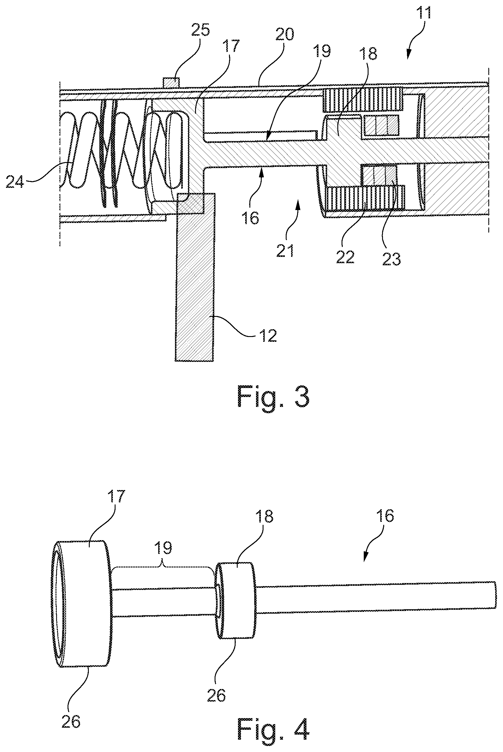
[0022] FIG. 3 a representation as in FIG. 2, however with another embodiment,
[0023] FIG. 4 a view of a control rod with two control regions according to the invention,
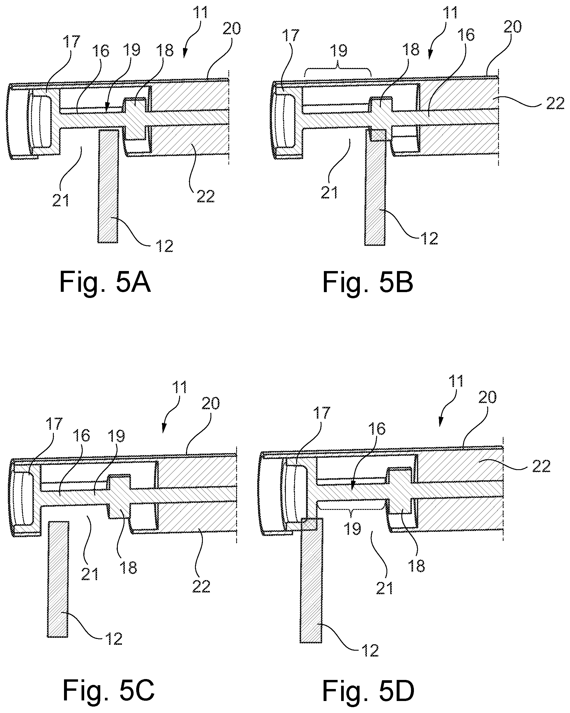
[0024] FIGS. 5A to 5D illustrate different control positions of the adjusting device.
DETAILED DESCRIPTION
[0025] According to FIG. 1, a valve train 1 according to the invention for an internal combustion engine 2 which is not shown in more detail comprises a camshaft 3 with a first cam 4 and a second cam 5 arranged axially adjacent thereto. Likewise provided is a rocker lever assembly 6 with a shifting pin 8 that is adjustable in the axial direction 7 between at least positions, on which a cam follower 9, in particular a cam roller 10, is mounted. Likewise provided are an adjusting device 11 (see also FIGS. 2, 3 and 5) and an adjustable control pin 12, which is arranged in the shifting pin 8, in particular radially mounted in the same. According to the invention, a guide contour 13 having a first guide track 14 and a second guide track 15 intersecting the same X-like is now arranged on the camshaft 3. Here, the control pin 12 optionally engages into the first or second guide track 14, 15 (according to FIG. 1, into the first guide track 14) and thereby adjusts the shifting pin 8 with the cam followers 9 arranged thereon between its/their two positions, wherein the cam follower 9, here the cam roller 10, in a first position of the shifting pin 8, interacts with the first cam 4 and in the second position of the shifting pin 8 with the second cam 5. According to FIG. 1, the rocker lever assembly 6 comprises two cam followers 9, both of which are coaxially rotatably arranged on the shifting pin 8 and each of which interacts either with an associated first cam 4 or an associated second cam 5.
[0026] In addition to this, the adjusting device 11 comprises a control rod 16 (see also FIG. 4) that is shiftable parallel to the shifting pin 8, i.e. in the axial direction 7, with a first control region 17, a second control region 18 and a neutral region 19 arranged in the axial direction in between. Upon a contact with the first control region 17, the control pin 12 is adjusted into the first guide track 14 while upon a contact with the second control region 18 it is adjusted into the second guide track 15. In the neutral region 19, the control pin 12 is neither in contact with the first control region 17, nor with the second control region 18 (see FIGS. 5a and 5c), as a result of which no actuation of the control pin 14 by the adjusting device 11 takes place. With the adjusting device 11 according to the invention it is possible that in the shifting pin 8 merely a single control pin 12 has to be arranged, as a result of which a solution that is significantly less expensive in design with a lower number of parts and with a lower assembly expenditure can be achieved. Through the guide contour 13 according to the invention with the guide tracks 14, 15 intersecting X-like, a guide contour 13 can be additionally also created which is installation space-optimised in particular in the axial direction and because of this requires little space. Altogether, a solution that is simple in design and installation space-optimised can thus be created with the valve train 1 according to the invention.
[0027] Viewing FIGS. 1 to 5 further it is noticeable that the adjusting device 11 comprises a housing 20 in which the control rod 16 is guided or mounted. In the present case, the housing 20 is cylindrical in design and comprises a shell opening 21, via which the control pin 12 can enter into contact with the control regions 17, 18. The shell opening 21 can be arranged centrally on the adjusting device 11 or on one side at an end of the housing 20. Here, the control rod 16 is comparatively easy to produce, for example by turning or thermal joining of the two control regions 17, 18 on the control rod 16, as a result of which an adjusting device 11 that is simple in design and thus cost-effective can be created. The circumstance that the adjusting device 11 in the installed state (see FIG. 1) is arranged in such a manner that the shell opening 21 faces downwards, the control rod 16 is also arranged protected within the housing 2 since in particular oil striking the housing 20 cannot enter the same.
[0028] For actuating or adjusting the control rod 16 with the control regions 17, 18 arranged thereon a solenoid 22, in particular in the manner of a coil surrounding the control rod (16) (see FIG. 2) or in the manner of a coil surrounding the second control region 18 (see FIG. 3) is provided, wherein in addition according to FIG. 3 a permanent magnet 23 is arranged on the control rod 16. This permanent magnet 23 can obviously be integrated in the control rod 16 in another manner, as is shown for example according to FIG. 2. Purely theoretically, the control rod 16 can also consist of a magnetisable material and thereby be subjected to the forces required for adjusting the control rod 16 by the solenoid 22.
[0029] Viewing FIGS. 1 to 3 it is noticeable that at least one spring 24 is provided, which preloads the control rod 16 and thereby also the two control regions 17, 18 into its first or second position, here into its second position. By means of such a spring 24, a failsafe function can be realised in particular, which enforces a predefined position of the control rod 16 upon a failure of the solenoid 22 or generally upon a failure of an actuation device for adjusting the control rod 16. Alternatively to the spring 24, a further solenoid 22 can obviously be provided so that in this case a total of two solenoids 22 are provided, which upon corresponding energisation, adjust the control rod 16 into its first or second position.
[0030] Viewing FIGS. 1 to 5 it is noticeable that the first control region 17 is arranged on the longitudinal end side of the control rod 16 and at the same time formed pot-like, wherein the spring 24, which in the present case is embodied as a coil spring, is at least partly arranged in the first control region 17. By way of this, a protected arrangement of the spring 24 can be achieved in the housing 20 and in the direction of the shell opening 21 a protected arrangement over the first control region 17 can be achieved. A position sensor 25, for example a Hall sensor, via which a position of the control rod 16 and thus a position of the two control regions 17, 18 is detectable can likewise be provided. By way of this, the exact control position can be transmitted for example to a motor control in each case.
[0031] The first and/or the second control region 17, 18 can be embodied as cylindrical control discs. In order to improve a contact between the control pin 12 and the respective control region 17, 18, it can be additionally mooted that the first and/or the second control region 17, 18 comprises a flattened region 26 which serves as contact region for the control pin 12.
[0032] Viewing now the individual control positions of the adjusting device 11 according to the invention as per FIGS. 5A to 5D it is evident that according to FIG. 5a the actuator, i.e. in the present case the control rod 16, is retracted and the control pin 12 projects into the neutral region 19, in which no actuation of the same through the adjusting device 11, i.e. the first or second control region 17 or 18 takes place. According to FIG. 5b the adjusting device 11 is now activated. For example by energising the solenoid 22, as a result of which the control rod 16 has shifted to the left and the control pin 12 enters into contact with the second control region 18. By way of this, the control pin 12 is moved downwards and thereby adjusted into the second guide track 15, in the control pin 12 now runs and is shifted in the axial direction 5 to the left into the neutral region 19 by means of the guide track 15, as shown according to FIG. 5c. According to FIG. 5d, the control rod 16 is again moved to the right as a result of which the control pin 12 now enters into contact with the first control region 17, upon which the same adjusts the control pin 12 into the first guide track 14. Altogether it is evident from FIG. 5a to d that the path of the control rod 16 required for changing over from the first to the second cam 4, 5 or back is comparatively short, which likewise contributes towards minimising the installation space. In addition to this merely a single adjusting device 11 or a control pin 12 and a guide contour 13 for each cylinder is required with the valve train 1 according to the invention. As is evident, furthermore, from FIGS. 1 to 5, the two control regions 17, 18 have different diameters in order to thereby compensate for different cam strokes.
[0033] With the valve drive 1 according to the invention and the internal combustion engine 2 equipped with such according to the invention, a solution that is simple in design, cost effective and additionally installation space-optimised for changing over between different cam profiles can thus be achieved.
* * * * *
D00000
D00001
D00002
D00003
XML
uspto.report is an independent third-party trademark research tool that is not affiliated, endorsed, or sponsored by the United States Patent and Trademark Office (USPTO) or any other governmental organization. The information provided by uspto.report is based on publicly available data at the time of writing and is intended for informational purposes only.
While we strive to provide accurate and up-to-date information, we do not guarantee the accuracy, completeness, reliability, or suitability of the information displayed on this site. The use of this site is at your own risk. Any reliance you place on such information is therefore strictly at your own risk.
All official trademark data, including owner information, should be verified by visiting the official USPTO website at www.uspto.gov. This site is not intended to replace professional legal advice and should not be used as a substitute for consulting with a legal professional who is knowledgeable about trademark law.