Thin Stabilized Segmental Wall Blocks, Soil Reinforcing System, And Methods
Liew; Willie ; et al.
U.S. patent application number 16/770284 was filed with the patent office on 2020-10-01 for thin stabilized segmental wall blocks, soil reinforcing system, and methods. This patent application is currently assigned to Tensar International Corporation. The applicant listed for this patent is Tensar International Corporation. Invention is credited to Willie Liew, Stephen A. Luptak, Andres F. Peralta, Aaron D. Smith, Kord J. Wissmann.
| Application Number | 20200308800 16/770284 |
| Document ID | / |
| Family ID | 1000004927231 |
| Filed Date | 2020-10-01 |

View All Diagrams
| United States Patent Application | 20200308800 |
| Kind Code | A1 |
| Liew; Willie ; et al. | October 1, 2020 |
THIN STABILIZED SEGMENTAL WALL BLOCKS, SOIL REINFORCING SYSTEM, AND METHODS
Abstract
A segmental wall block, soil reinforcing system, and method related thereto, wherein the wall block may be used for constructing retaining walls. In one embodiment, the segmental wall block may include: a front face; a rear face; a slot disposed along the rear face; a troughed top face; a bottom face; a first and second open core extending from the top face to the bottom face; a first side having a tongue; and an opposing second side having a groove, wherein the tongue is shaped to interlock with the groove. A soil system may include: a wall block component including a first configuration of interlocked segmented wall blocks as described, and a stabilizing component. A method of reinforcing soil may include the steps of: installing a leveling pad of concrete or gravel; and providing a soil stabilizing system.
| Inventors: | Liew; Willie; (Alpharetta, GA) ; Peralta; Andres F.; (Alpharetta, GA) ; Wissmann; Kord J.; (Alpharetta, GA) ; Luptak; Stephen A.; (Alpharetta, GA) ; Smith; Aaron D.; (Alpharetta, GA) | ||||||||||
| Applicant: |
|
||||||||||
|---|---|---|---|---|---|---|---|---|---|---|---|
| Assignee: | Tensar International
Corporation Alpharetta GA |
||||||||||
| Family ID: | 1000004927231 | ||||||||||
| Appl. No.: | 16/770284 | ||||||||||
| Filed: | December 11, 2018 | ||||||||||
| PCT Filed: | December 11, 2018 | ||||||||||
| PCT NO: | PCT/US2018/064996 | ||||||||||
| 371 Date: | June 5, 2020 |
Related U.S. Patent Documents
| Application Number | Filing Date | Patent Number | ||
|---|---|---|---|---|
| 62596939 | Dec 11, 2017 | |||
| Current U.S. Class: | 1/1 |
| Current CPC Class: | E02D 2300/0029 20130101; E02D 2600/30 20130101; E02D 2300/0084 20130101; E02D 2200/13 20130101; E02D 2300/0006 20130101; E02D 2300/002 20130101; E02D 2300/0009 20130101; E02D 29/025 20130101; E02D 2300/0079 20130101; E02D 2600/40 20130101; E02D 29/0266 20130101; E02D 2300/0015 20130101; E02D 29/0233 20130101 |
| International Class: | E02D 29/02 20060101 E02D029/02 |
Claims
1. A segmental wall block comprising: (a) a front face; (b) a rear face; (c) a slot disposed along the rear face; (c) a troughed top face; (d) a bottom face; (e) a first and second open core extending from the top face to the bottom face; (f) a first side having a tongue; and (g) an opposing second side having a groove, wherein the tongue is shaped to interlock with the groove.
2. The segmental wall block of claim 1, wherein the front face is textured.
3. The segmented wall block of claim 1, wherein the wall block has a length, a height, a depth, a tongue length, and a weight.
4. The segmented wall block of claim 3, wherein the length is from about 10 inches to about 36 inches.
5. The segmented wall block of claim 3, wherein the height is from about 6 inches to about 12 inches.
6. The segmented wall block of claim 3, wherein the depth is from about 5 inches to about 12 inches.
7. The segmented wall block of claim 3, wherein the tongue length is from about 1 inch to about 3 inches.
8. The segmented wall block of claim 3, wherein the weight is from about 35 lbs to about 60 lbs.
9. The segmented wall block of claim 1, further comprising a top groove along said top face adapted to receive a mechanical connector.
10. A soil reinforcing system comprising: a wall block component including a first configuration of interlocked segmented wall blocks, each of the wall blocks comprising: (a) a front face; (b) a rear face; (c) a slot disposed along the rear face; (c) a troughed top face; (d) a bottom face; (e) a first and second open core extending from the top face to the bottom face; (f) a first side having a tongue; and (g) an opposing second side having a groove, wherein the tongue is shaped to interlock with the groove; and a stabilizing component connected to the wall block component.
11. The soil reinforcing system of claim 10, wherein one or more of the wall blocks include a top groove along the top face adapted to receive a mechanical connector.
12. The soil reinforcing system of claim 10, wherein the stabilizing component comprises a stabilizing hoop connected intermittently to the slot at the rear face of the configuration of interlocked segmented wall blocks.
13. The soil reinforcing system of claim 12, wherein the stabilizing component further comprises a fill material in the stabilizing hoop.
14. The soil reinforcing system of claim 10, wherein the stabilizing component comprises an anchor connected to the slot.
15. The soil reinforcing system of claim 10, wherein the stabilizing component comprises a horizontal plate at the rear face.
16. The soil reinforcing system of claim 10, wherein the stabilizing component comprises a second configuration of segmented wall blocks, wherein one of the second configuration of segmented wall blocks is connected to the rear face of one of the first configuration of segmented wall blocks.
17. The soil reinforcing system of claim 10, wherein the stabilizing component is a geogrid structure,
18. The soil reinforcing system of claim 10, wherein the stabilizing component is a combination of stabilizing hoops and horizontal geogrids connected to the first configuration of wall blocks.
19. A method of reinforcing soil comprising the steps of: installing a leveling pad of concrete or gravel; providing at least three wall blocks, wherein each wall block has a rear face; a slot disposed along the rear face; a troughed top face; a bottom face; a first and second open core extending from the top face to the bottom face; a first side having a tongue; an opposing second side having a groove, wherein the tongue is shaped to interlock with the groove; forming a first row of the wall blocks by connecting the tongues and grooves of the at least three wall blocks; installing stabilizing elements at the rear face of the wall blocks; and placing backfill and compacting up to the first row of the wall blocks.
20. The method of claim 19 further comprising the steps of: providing a geogrid soil reinforcing strip and engaging the geogrid soil reinforcing strip to the groove of the first row of the wall blocks with one or more mechanical connectors; and placing a second row of the wall blocks while engaging the mechanical connectors of the first row of the wall blocks.
Description
CROSS-REFERENCE TO RELATED APPLICATIONS
[0001] The presently disclosed subject matter is related to and claims priority to U.S. Provisional Patent Application No. 62/596,939 entitled "Thin Stabilized Segmental Wall Blocks, Soil Reinforcing System, And Methods" filed on Dec. 11, 2017; the entire disclosure of which is incorporated herein by reference.
TECHNICAL FIELD
[0002] The presently disclosed subject matter relates generally to the retention of earthen formations and the field of retaining walls and more particularly to a thin stabilized segmental wall block, a soil reinforcing system, and methods related thereto.
BACKGROUND
[0003] Retaining walls are commonly used for architectural and site development applications and such soil reinforced earthen works have now become a recognized civil engineering structure useful in the retention of hillsides, right of way embankments, and the like. The wall facing elements, which typically consist of masonry blocks, concrete blocks, concrete panels, or welded wire forms, must withstand lateral pressures exerted by backfill soils. Reinforcement and stabilization of the soil backfill in mechanically stabilized earth applications is commonly provided using geosynthetic materials such as geogrids or geotextiles that are placed horizontally in the soil fill behind the wall face. The geosynthetic materials interlock with the soil and create a stable reinforced soil mass. The geosynthetic materials are connected to the wall face elements either mechanically with connectors or frictionally between wall face elements and geosynthetics.
[0004] A preferred form of grid-like tie-back sheet material used to reinforce the soil behind a retaining wall structure, known as an integral geogrid, is commercially available from The Tensar Corporation of Alpharetta, Ga. ("Tensar") and is made by the process disclosed in U.S. Pat. No. 4,374,798 ("the '798 patent"). Integral geogrid tie-back sheet material may be uniaxially oriented according to the '798 patent to provide grid-like sheets including a plurality of elongated, parallel, molecularly oriented strands with transversely extending bars integrally connected thereto by less oriented or unoriented junctions, the strands, bars and junctions together defining a multiplicity of elongated openings. With biaxial (i.e., 2-dimensional) stretching, the bars may be oriented into elongated strands. While integral geogrids are preferred as reinforcing materials in the construction of retaining walls, other forms of tie-back sheet materials have been used in a similar manner.
[0005] The use of full height pre-cast concrete wall panels for wall-facing elements in a retaining wall is known, such as is disclosed in U.S. Pat. Nos. 5,568,998 and 5,580,191. These types of systems typically require, during construction, that the panels be placed using a crane because they are very large, perhaps 5 feet by 10 feet or even larger and, as a result, are quite heavy such that they cannot be readily man-handled. To avoid such problems in the use of pre-cast wall panels, other types of retaining wall structures have been developed.
[0006] As one known example, retaining walls have been formed from modular wall blocks which are typically relatively small cementitious blocks as compared to precast wall panels. The assembly of modular wall blocks usually does not require heavy equipment. Such modular wall blocks can be handled by a single person and are used to form retaining wall structures by arranging a plurality of blocks in courses superimposed on each other, much like laying of brick or the like. Each block includes a body with a front face which forms the exterior surface of the formed retaining wall. Examples of such modular wall block systems are disclosed in U.S. Pat. Nos. 5,010,707; 5,522,682; 5,568,999; 5,823,709; 5,911,539; 5,934,838; and 6,287,054.
[0007] The use of welded wire (WW) facing units in the construction of retaining walls is also well known to reinforce earthen formations. U.S. Pat. Nos. 4,856,939; 6,595,726; and 8,197,159 disclose the construction of geogrid-reinforced earthen retaining walls incorporating welded wire facing units wherein portions of the face sections of the wire facing units include kinks or hooks which serve, inter alia, to retain the ends of geogrids, the remainder of the geogrids being designed to extend rearwardly into the fill to reinforce the wall. U.S. Pat. No. 4,904,124 also discloses the use of wire "baskets" that are designed to be filled with granular or rock material to define the forward or face of the wall, the elements of which are also reinforced with grid-like reinforcing sheet material to provide stability of the soil mass.
[0008] In the case of modular block walls that are typically used for structural earth walls, the block is normally 11 to 12 inches deep and weigh between 75 to 100 pounds (lbs) to provide stability to the facing during wall installation. The weight is relatively heavy and would require lifting by two persons or handled with small equipment with a block picking tool since Occupational Safety and Health Administration (OSHA) limit the maximum weight to be carried by a person to 50 lbs. This typically leads to slower wall installation or increased costs for the wall.
[0009] As such, improvements in the art are desired to provide a retaining wall block system that utilize thin and lightweight block to ease wall installation and improve productivity while maintaining the structural integrity and stability of the block wall system. A thin block would allow for an increase to the loading capacity or area of block onto a truck compared to traditional blocks, thus saving transportation costs and reducing environmental impacts. A thin block could be placed faster and requires less costly and environmentally harmful cement during fabrication. A thin block must, however, include provisions for block stability during construction and during wall loading.
SUMMARY
[0010] A segmental wall block, soil reinforcing system, and method related thereto are disclosed. The wall block may be used for constructing retaining walls.
[0011] In one embodiment, the segmental wall block includes: a front face; a rear face; a slot disposed along the rear face; a troughed top face; a bottom face; a first and second open core extending from the top face to the bottom face; a first side having a tongue; and an opposing second side having a groove, wherein the tongue is shaped to interlock with the groove.
[0012] In another embodiment, a segmental wall block may include a front face that is textured.
[0013] The segmental wall block may have a length from about 10 inches to about 36 inches; a height from about 6 inches to about 12 inches; a depth from about 5 inches to about 12 inches; a tongue length from about 1 inch to about 3 inches; and a weight from about 35 lbs to about 60 lbs.
[0014] Further, the segmented wall block may include a top groove along the top face that is adapated to receive a mechanical connector.
[0015] A soil reinforcing system of the present invention may include: a wall block component including a first configuration of interlocked segmented wall blocks, each of the wall blocks including: a front face; a rear face; a slot disposed along the rear face; a troughed top face; a bottom face; a first and second open core extending from the top face to the bottom face; a first side having a tongue; and an opposing second side having a groove, wherein the tongue is shaped to interlock with the groove; and a stabilizing component connected to the wall block component.
[0016] The stabilizing component may include a stabilizing hoop connected intermittently to the slot at the rear face of the configuration of interlocked segmented wall blocks. The stabilizing component may further include a fill material in the stabilizing hoop.
[0017] The stabilizing component may further include an anchor connected to the slot or may include a horizontal plate at the rear face.
[0018] The stabilizing component may include a second configuration of segmented wall blocks, wherein one of the second configuration of segmented wall blocks is connected to the rear face of one of the first configuration of segmented wall blocks.
[0019] The stabilizing component may include a geogrid structure, or the stabilizing component may include a combination of stabilizing hoops and horizontal geogrids connected to the first configuration of wall blocks.
[0020] A method of reinforcing soil may include the steps of: installing a leveling pad of concrete or gravel; providing at least three wall blocks, wherein each wall block has a rear face; a slot disposed along the rear face; a troughed top face; a bottom face; a first and second open core extending from the top face to the bottom face; a first side having a tongue; an opposing second side having a groove, wherein the tongue is shaped to interlock with the groove; forming a first row of the wall blocks by connecting the tongues and grooves of the at least three wall blocks; installing stabilizing elements at the rear face of the wall blocks; placing backfill and compacting up to the first row of the wall blocks; and optionally, the steps of: providing a geogrid soil reinforcing strip and engaging the geogrid soil reinforcing strip to the groove of the first row of the wall blocks with one or more mechanical connectors; and placing a second row of the wall blocks while engaging the mechanical connectors of the first row of the wall blocks.
BRIEF DESCRIPTION OF THE DRAWINGS
[0021] Having thus described the presently disclosed subject matter in general terms, reference will now be made to the accompanying Drawings, which are not necessarily drawn to scale, and wherein:
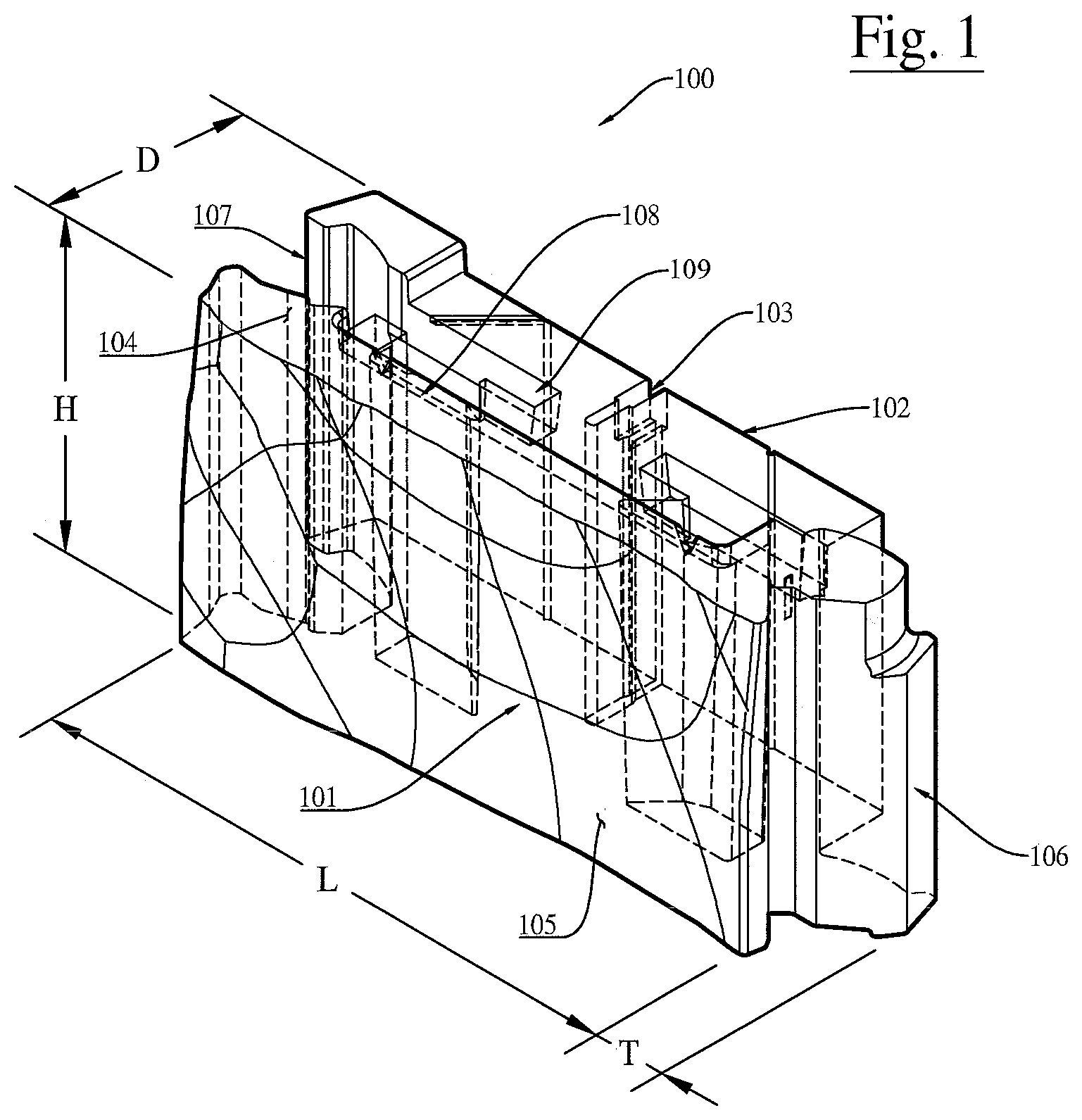
[0022] FIG. 1 illustrates a perspective view of an example of the presently disclosed wall block, wherein the wall block can be used to form retaining walls and/or any other soil reinforcing element;
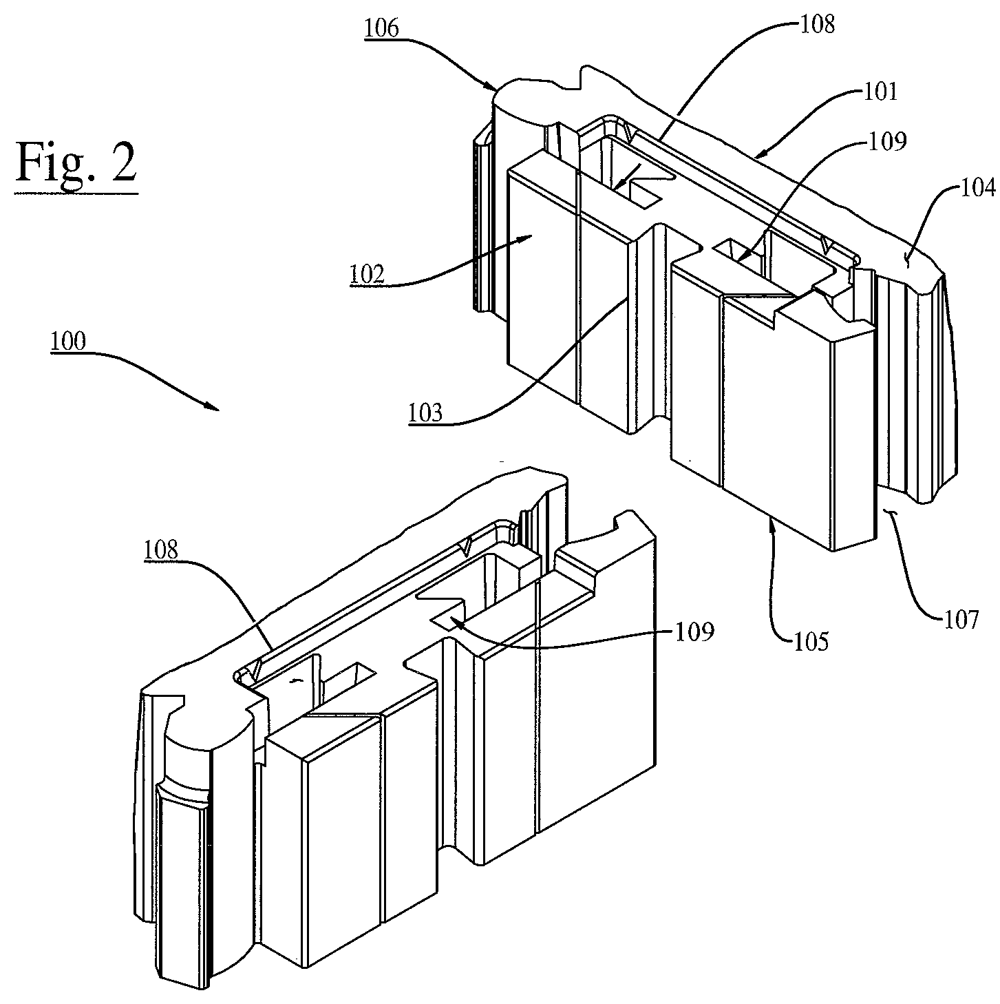
[0023] FIG. 2 illustrates a perspective view of a slight variation at the rear to the wall block of the presently disclosed wall block shown in FIG. 1;
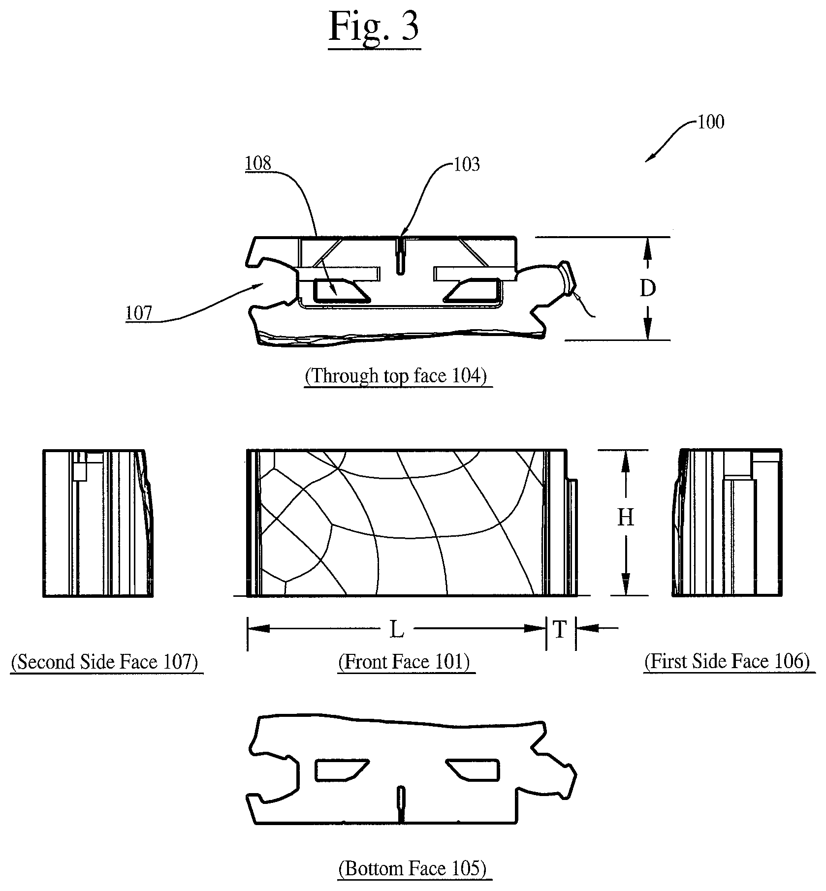
[0024] FIG. 3 illustrates a front view, a top view, a bottom view, and two end views of the wall block shown in FIG. 1;
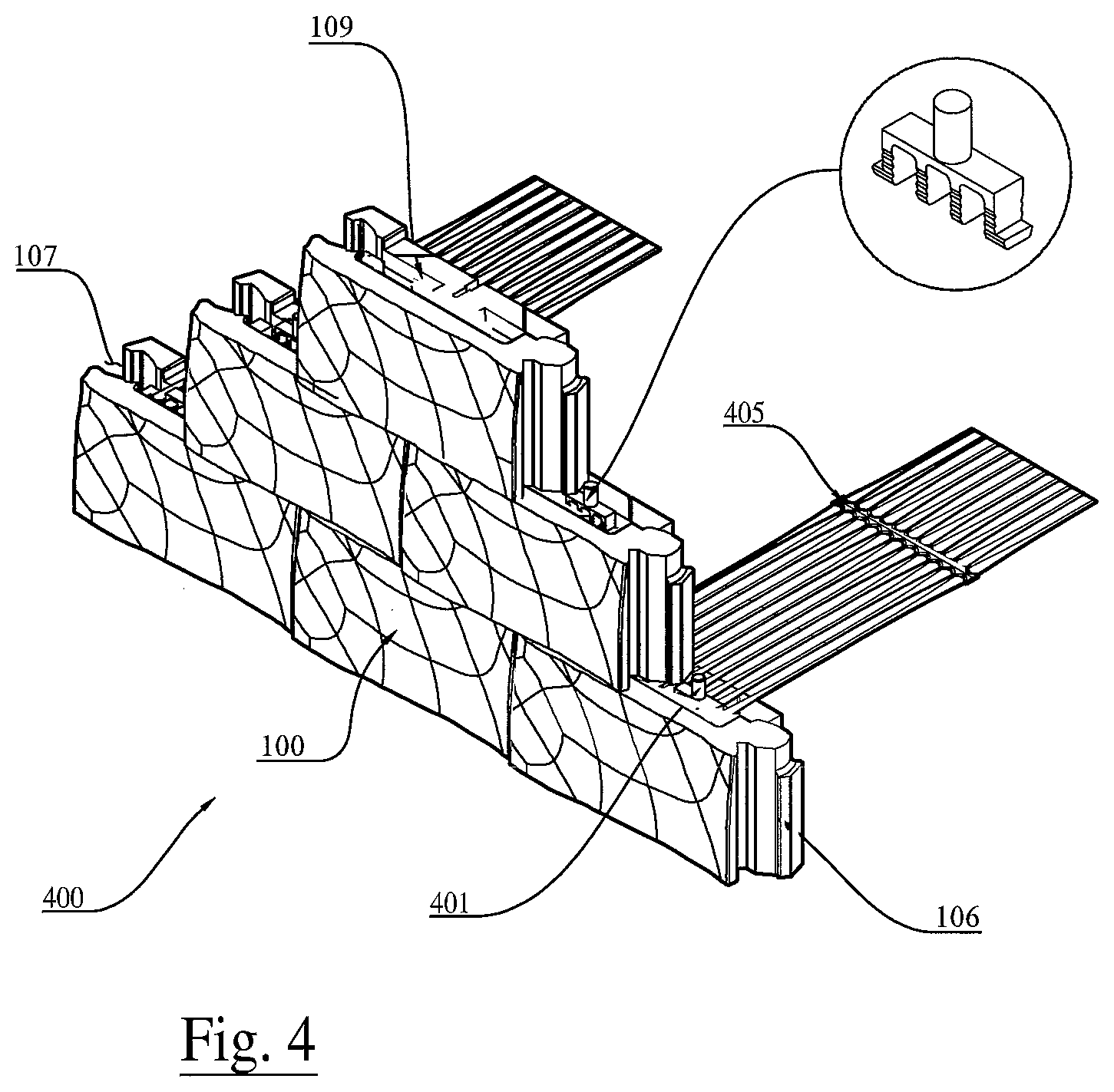
[0025] FIG. 4 illustrates a perspective top view of an example of a soil reinforcing system that includes an arrangement of the presently disclosed wall blocks;
[0026] FIG. 5, FIG. 6, FIG. 7 and FIG. 8 illustrate various stabilizing systems of the presently disclosed wall blocks;
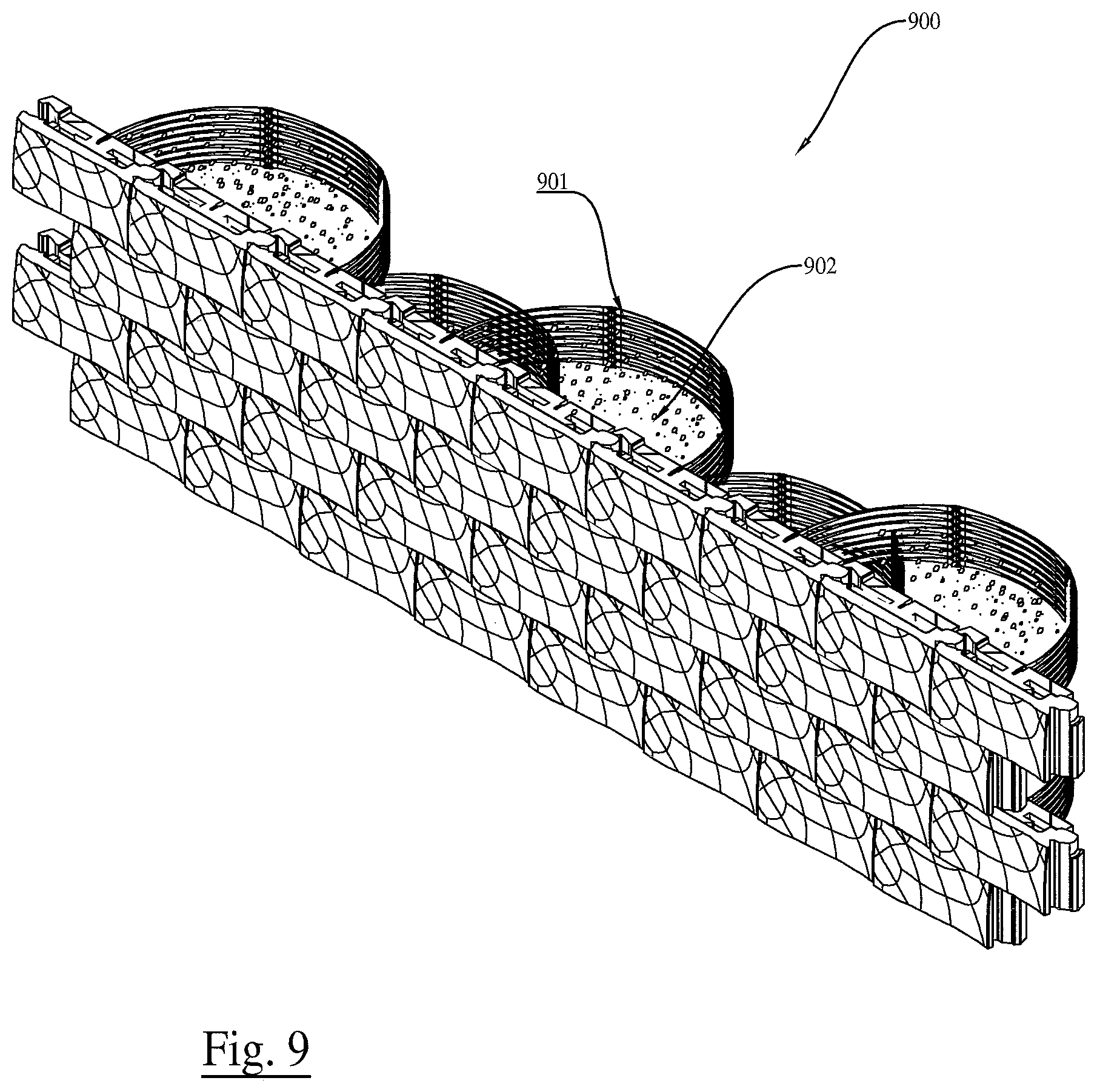
[0027] FIG. 9 illustrates a perspective view of a free-standing gravity wall utilizing stabilizing elements of the present subject matter;
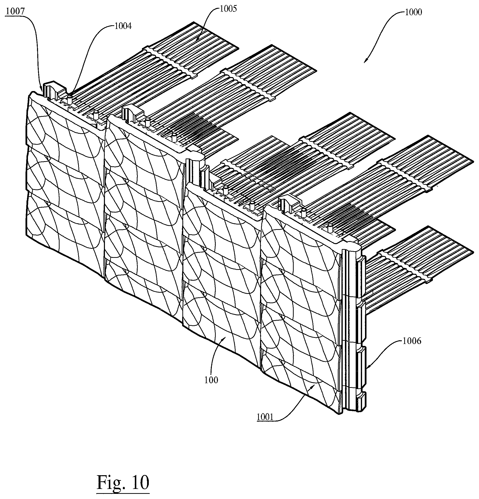
[0028] FIG. 10 illustrates a perspective view of another arrangement of the presently disclosed wall blocks;
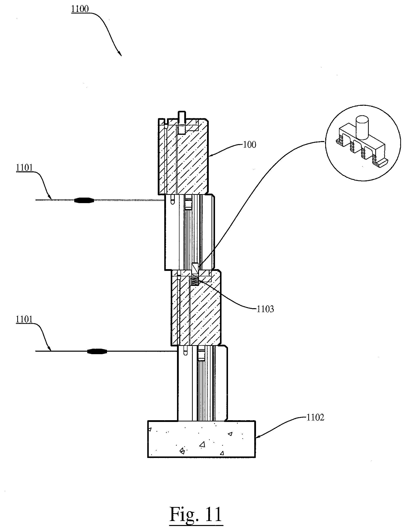
[0029] FIG. 11 illustrate a cross-section view of a soil reinforcing system of the present subject matter;
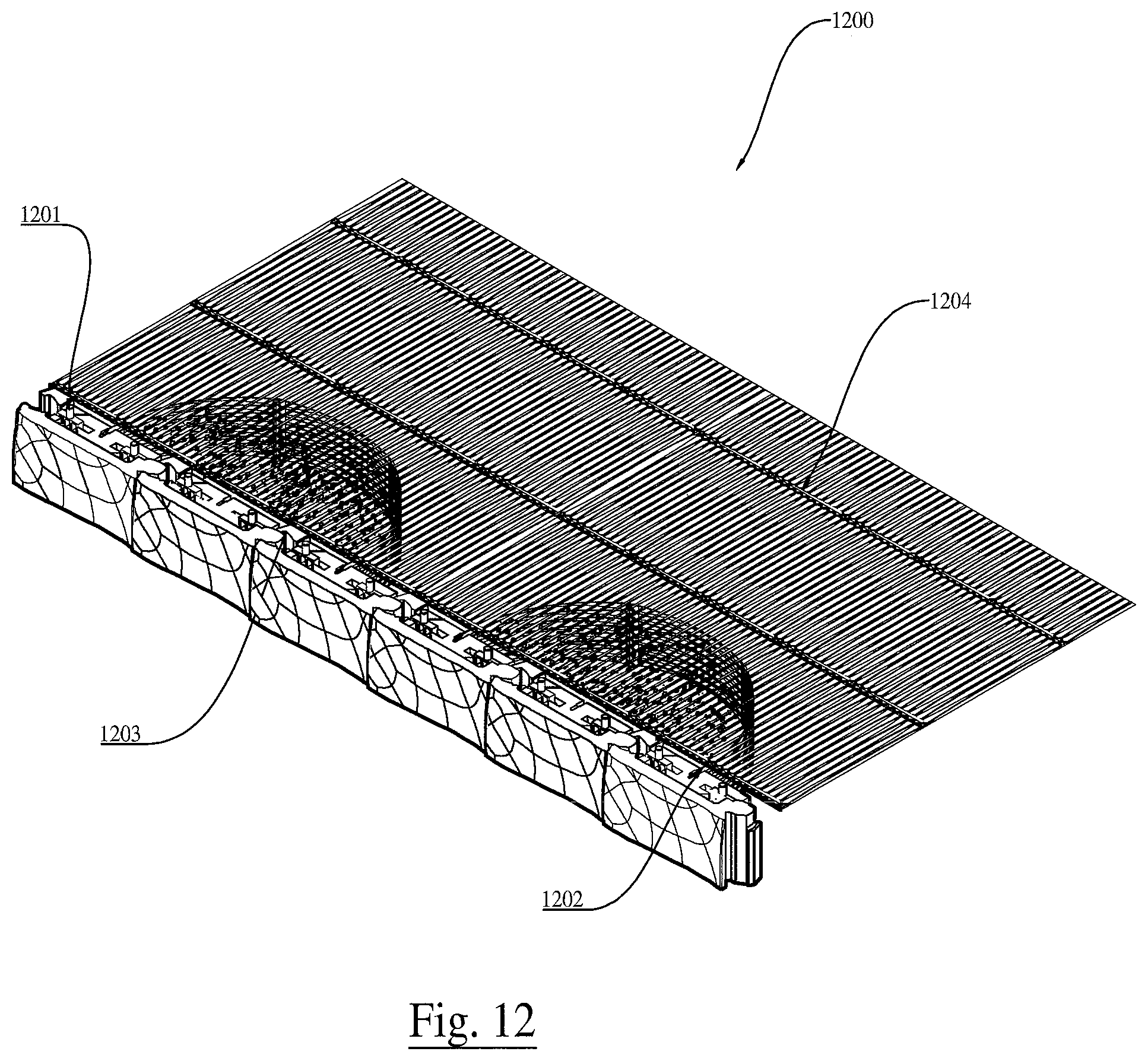
[0030] FIG. 12 illustrates a perspective view of a connection variation to the presently disclosed soil reinforcing system shown in FIG. 4;
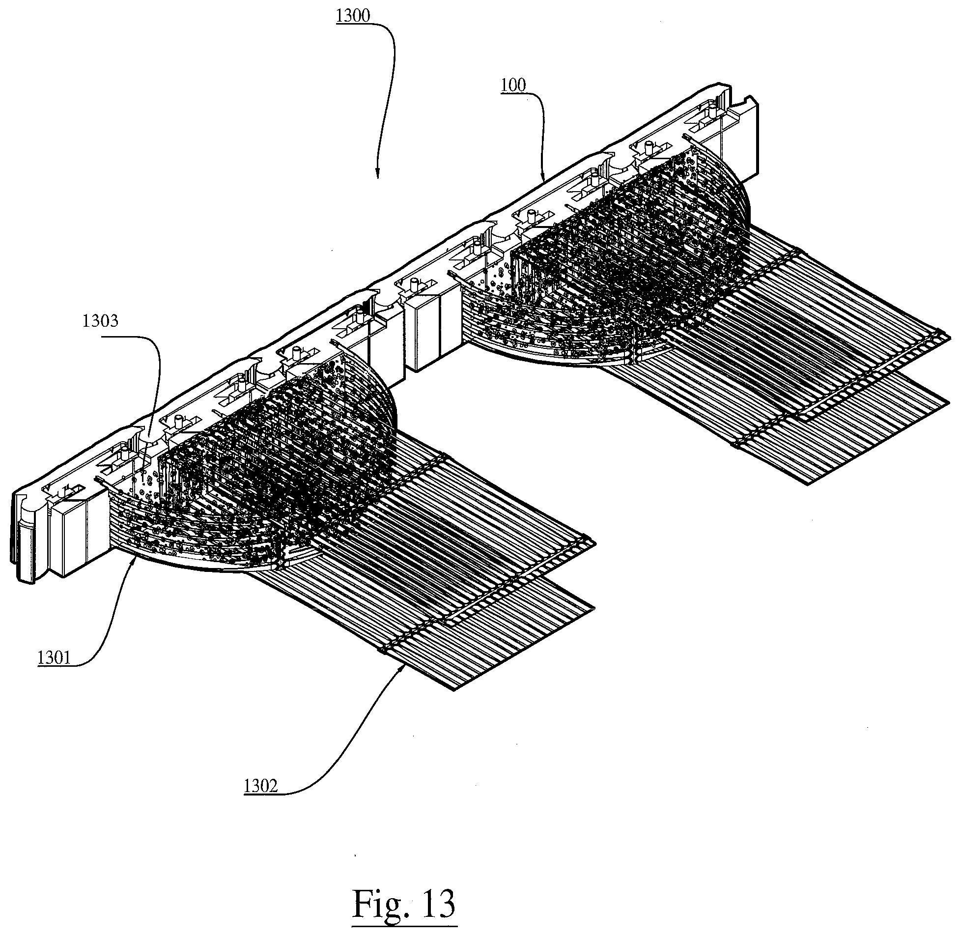
[0031] FIG. 13 illustrates a perspective view of another connection variation to the presently disclosed soil reinforcing system shown in FIG. 4; and
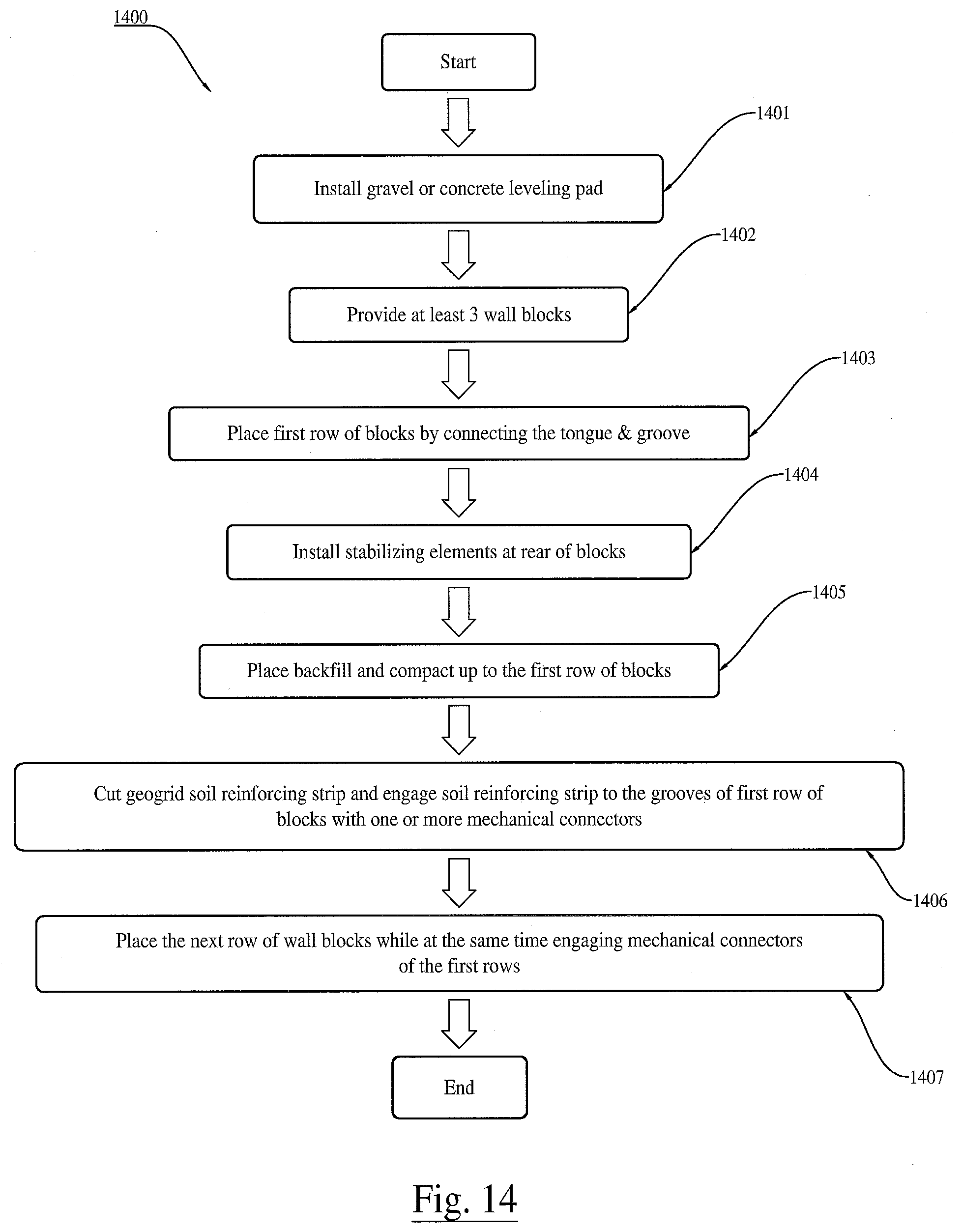
[0032] FIG. 14 illustrates a flow diagram of an example of a method of using the presently disclosed wall blocks.
DETAILED DESCRIPTION
[0033] The presently disclosed subject matter now will be described more fully hereinafter with reference to the accompanying Drawings, in which some, but not all embodiments of the presently disclosed subject matter are shown. Like numbers refer to like elements throughout. The presently disclosed subject matter may be embodied in many different forms and should not be construed as limited to the embodiments set forth herein; rather, these embodiments are provided so that this disclosure will satisfy applicable legal requirements. Indeed, many modifications and other embodiments of the presently disclosed subject matter set forth herein will come to mind to one skilled in the art to which the presently disclosed subject matter pertains having the benefit of the teachings presented in the foregoing descriptions and the associated Drawings. Therefore, it is to be understood that the presently disclosed subject matter is not to be limited to the specific embodiments disclosed and that modifications and other embodiments are intended to be included within the scope of the appended claims.
[0034] In some embodiments, the presently disclosed subject matter provides a thin stabilized segmental wall block, a soil reinforcing system, and methods related thereto. The presently disclosed thin stabilized segmental wall block can be, for example, a concrete masonry block used for constructing retaining walls. The thin stabilized segmental wall block would typically be fabricated through a dry-cast process but also may be fabricated through a wet-cast process. The wall block would ease lifting and installation with the lightweight nature of the block.
[0035] An aspect of the presently disclosed thin stabilized block would typically have a height of no more than 8 inches, a length less than 18 inches, and depth less than 6 inches. The typical weight of the block would be less than 50 lbs. The thin and light block would likely not be stable by itself to support the lateral load and vibration during construction of the modular block wall systems. The thin and light block will need to be stabilized with other means or methods for stability during construction of the modular block wall systems.
[0036] An aspect of the presently disclosed wall block is that it may include a tongue and groove system for support of the construction of modular block wall systems, wherein wall blocks would interlock side to side to provide rigidity to the facing and improve alignment of the wall system.
[0037] Another aspect of the presently disclosed wall block is that it may include a "behind the face" groove for receiving mechanical connectors for simple connection to adjacent wall blocks and/or to any other soil reinforcing elements, such as, but not limited to, a geogrid.
[0038] Yet another aspect of the presently disclosed wall block is that it may include a slot or groove at the top or at the rear of the wall blocks for receiving a stabilizing element to increase stability of the lightweight stabilized block during construction.
[0039] Still another aspect of the presently disclosed wall block is that it may feature decreased block weight and increased production rate as compared with conventional wall blocks.
[0040] Referring now to FIG. 1 and FIG. 2 are perspective views of an example of the presently disclosed wall block 100, wherein the wall block 100 can be used to form free-standing gravity walls, retaining walls and/or any other soil reinforcing structure. Further, FIG. 3 shows a front view, a top view, a bottom view, and two end views of the wall block 100 shown in FIG. 1.
[0041] The wall block 100 can be, for example, a concrete masonry block used for constructing retaining walls. That is, the wall block 100 is an example of a modular wall block. The wall block 100 typically includes a front face 101, a rear face 102 that has a slot/groove at the center 103, a troughed top face 104, and a flat bottom face 105. Accordingly, the wall block 100 has a tongue 106 on one side and a groove 107 on the other side. The wall block 100 can also include top grooves 109 at the top face 104. Additionally, two hollow open cores 108 pass through the wall block 100, extending from the troughed top face 104 to the flat bottom face 105. Optionally, the front face 101 of block 100 can be textured to provide a certain appearance and/or aesthetic feature.
[0042] The terms "top," "bottom," "front," "rear," "over," "under," and "on" are used throughout the description with reference to the relative positions of components of the wall block 100, such as relative positions of the front, rear, top, and bottom faces of the wall block 100. It will be appreciated that the wall block 100 is functional regardless of its orientation in space.
[0043] The wall block 100 has a length L, a height H, a depth D, and extended tongue T. The length L of the wall block 100 can generally be from about 10 inches to about 36 inches, and in a preferred embodiment of approximately 16 inches. The height H of the wall block 100 can generally be from about 6 inches to about 12 inches, and in a preferred embodiment of approximately 8 inches. The depth D of the wall block 100 can generally be from about 5 inches to about 12 inches, and in a preferred embodiment of approximately 5.5 inches. The extended tongue T of the wall block 100 can generally be from 1 inch to 3 inches, an in a preferred embodiment of approximately 1.6 inches.
[0044] The wall block 100 is lightweight, and generally can weigh between 35 lbs to 60 lbs, and in a preferred embodiment of approximately 48 lbs. The lightweight wall block 100 would be stabilized with various means of stabilizing elements to control alignment and movement during application of construction loads.
[0045] Referring now to FIG. 4, a soil reinforcing system 400 is shown including a configuration of wall blocks 100 that can be stacked in the standard running bond configuration utilizing a combination of one or more connectors, such as mechanical connectors 401, to connect one wall block 100 to another wall block 100 on top and below it and/or to connect the wall block 100 to any other soil reinforcing elements. Accordingly, a top groove 109 along the top of wall block 100 is provided to receive the mechanical connector 401; the groove 109 has a certain width and depth. The mechanical connectors 401 along with the stabilizing elements provide vertical stability to the thin and lightweight wall blocks 100.
[0046] The tongue 106 of wall block 100 is shaped to fit the side groove 107 to create an interlock mechanism and provide lateral stability between wall blocks 100. The shape of the tongue 106 and groove 107 would interlock wall blocks 100 side to side on a straight wall and for a wide range of convex and concave curvatures.
[0047] The soil reinforcing system includes a soil reinforcing element 405 that may be, for example, a synthetic material, such as high-density polyethylene (HDPE) and polyester geogrids, or may be a steel reinforcing mesh, steel strips, or other soil reinforcing elements. A "geogrid" is a grid whose primary purpose is to strengthen or reinforce soil and has open meshes into which soil particles can lock. The soil reinforcing element 405 can generally be a full sheet-like soil reinforcement and in the preferred embodiment a narrow strip reinforcement from about 6 inches to 20 inches, and in a preferred embodiment of approximately 10 inches.
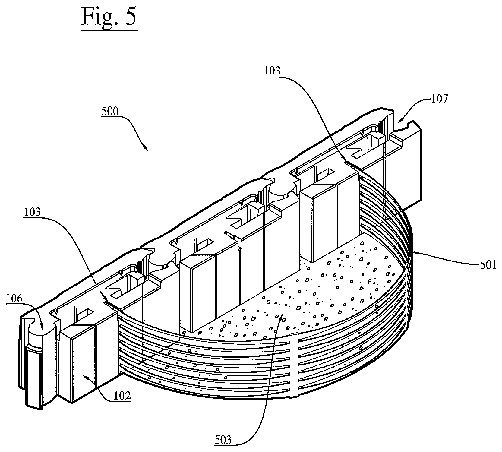
[0048] Referring now to FIG. 5 is a perspective view of an example of stabilizing system 500 of an arrangement of presently disclosed wall blocks 100 to provide overturning stability to the thin stabilized wall blocks during construction. In the wall blocks stabilizing system 500, the wall blocks 100 are interlocked side to side with the tongue 106 and groove 107 while also connected to a stabilizing hoop 501 at the rear face 102 of the wall block 100 at the wall block slot/groove 103 intermittently along the wall. The stabilizing hoop 501 may be a synthetic material such as HDPE or PET geogrids, or may be a steel reinforcing mesh or strap or band. The hoop 501 is then filled with gravel or stone 503 to complete the stabilizing system. The stabilizing hoop is spaced at an interval required to provide adequate overturning stability to the wall blocks 100 during construction. While a stabilizing hoop is discussed herein, it is contemplated that the structure may include any suitable box/frame structure (e.g., rectangular, oval, triangular, etc.), flexible or rigid, for stone retention and block stabilization.
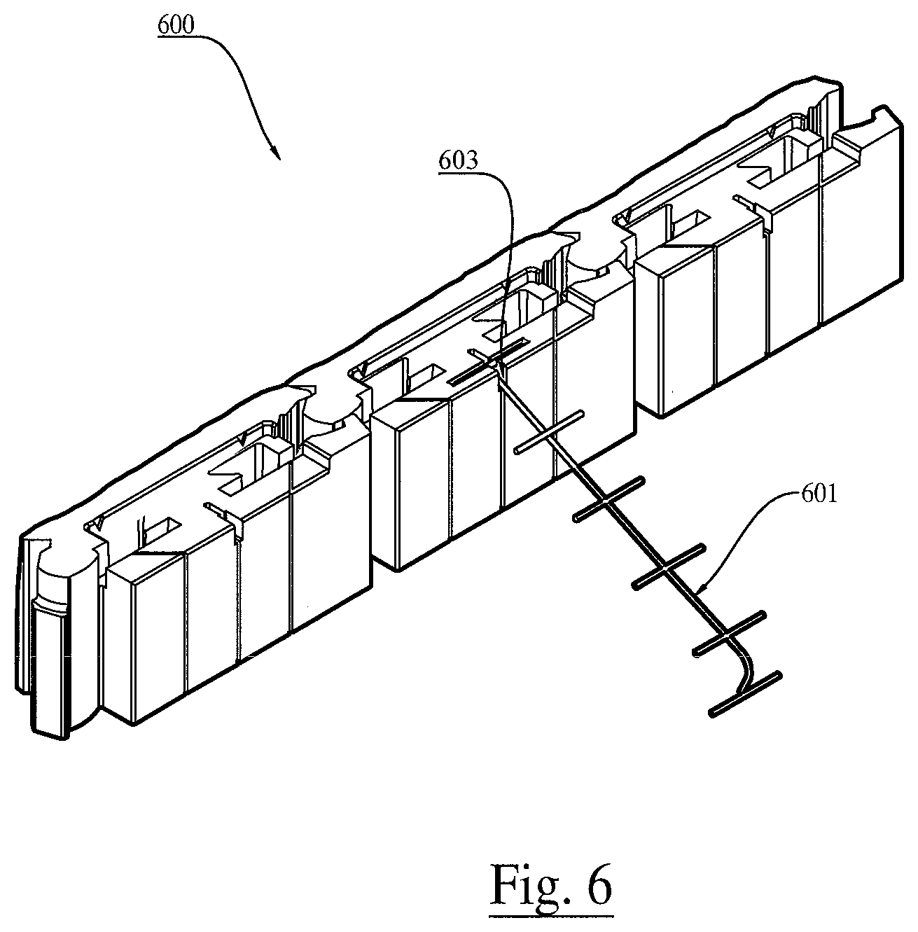
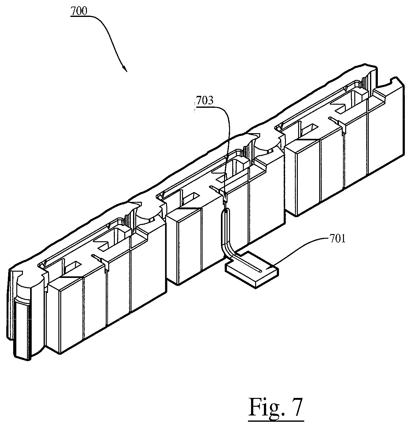
[0049] Referring now to FIG. 6, FIG. 7, and FIG. 8. are perspective views of other examples of wall blocks 100 used in stabilizing systems 600, 700, and 800. For example, FIG. 6 shows wall block 100 stabilized with a welded wire anchor 601 connected to slot 603 at the rear of the block. The welded wire anchor provides overturning stability through pullout anchorage. FIG. 7 shows wall block 100 stabilized with a horizontal plate 701 placed at the rear and bottom of the block but connected to the block through the slot 703. The horizontal plate 701 engages the overburden pressure from the backfill behind the reinforced wall and thus increases the overturning stability of the stabilized wall blocks. All stabilizing elements are spaced at intervals required to provide adequate overturning stability to the wall blocks 100 during construction.
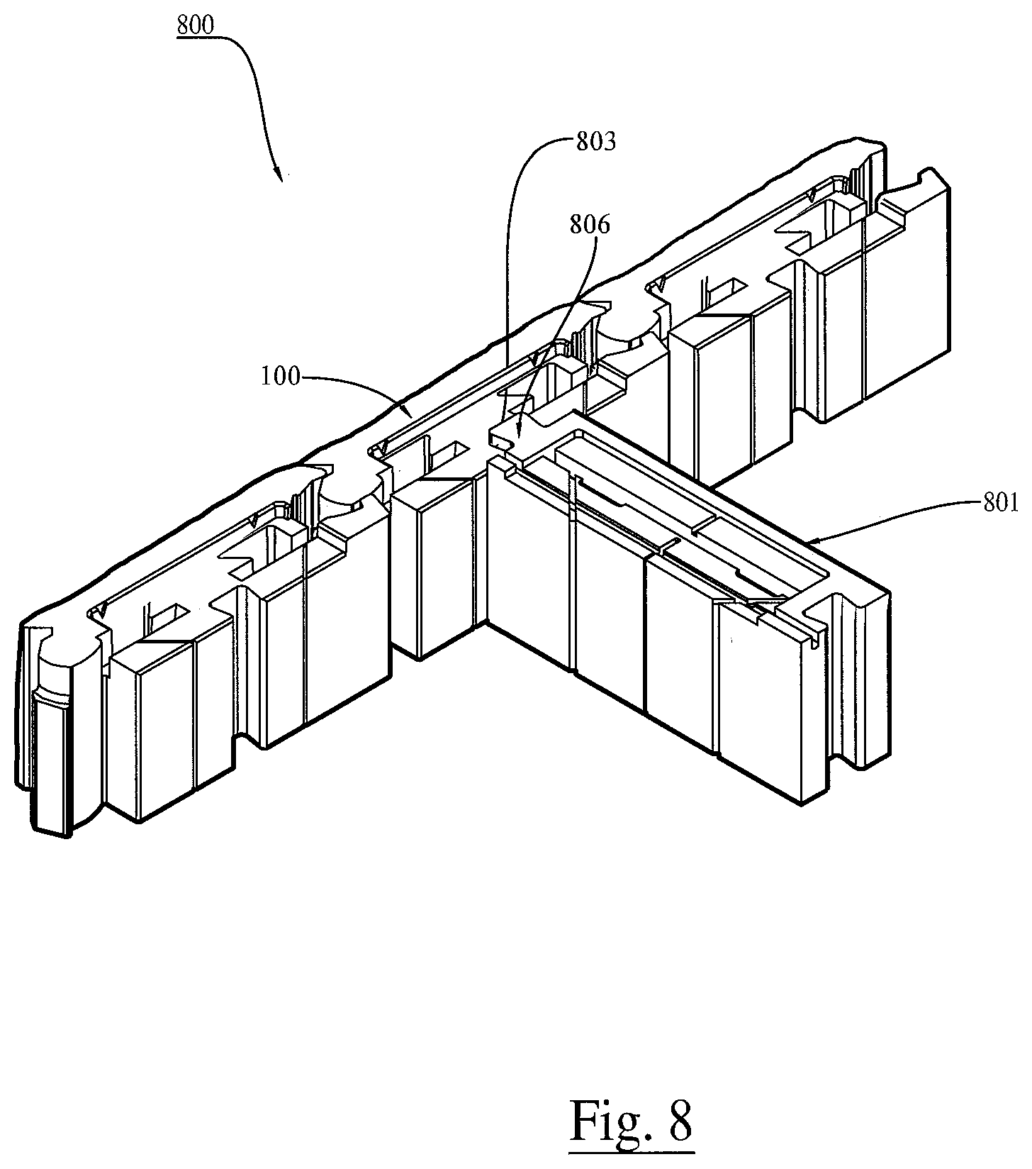
[0050] In another example, FIG. 8 shows wall blocks 100 stabilized with wall block 801 or series of wall blocks 801 by engaging the tongue 806 of wall block 801 through the groove 803 at the rear of the wall block 100 and therefore creates a stabilized system 800. The stabilizing wall block 801, which may be of variable height, thickness and depth, acts as an anchor to provide overturning stability to the wall block 100.
[0051] Referring now to FIG. 9 is a perspective view of a free-standing gravity wall system 900 utilizing wall blocks 100 and a series of stabilizing hoops 901 filled with soil fill 902. The soil weight of the confined soil fill 902 in the stabilizing hoop 901 increases the effective depth of the retaining wall to provide sufficient vertical overburden weight to resist the lateral pressure from the soil behind the stabilizing hoop.
[0052] Referring now to FIG. 10 is a perspective view of another arrangement of wall block 100 in stacked bond configuration 1000. In this arrangement, half-height block 1001 span between two wall blocks 100 at the first row and the top row of the retaining wall. The tongue 1006 and groove 1007 of wall block 1001 and 100 will be stacked on top of one another, creating stacked vertical joints. Wall blocks 100 and 1001 are connected to the soil reinforcing 1005 with one or more mechanical connectors 1004.
[0053] Referring now to FIG. 11 is a cross-section view of soil reinforcing system 1100. The first layer of wall block 100 may be placed on a leveling pad 1102 consisting of gravel or concrete. The soil reinforcing system 1100 typically includes a first soil reinforcing element 1101 that is integrated at a lower portion of the wall blocks 100 and a second soil reinforcing element 1101 that maybe integrated at an upper portion of the wall blocks. In one example, the soil reinforcing elements 1101 are geogrid structures. A "geogrid" is a grid whose primary purpose is to strengthen or reinforce soil and has open meshes into which soil particles can lock.
[0054] In the soil reinforcing system 1100 of the present invention, multiple mechanical connectors 1103 may be used to couple one wall block 100 to another and to couple the wall blocks 100 to the soil reinforcing elements 1101. The mechanical connectors 1103 are often mechanical block connectors and alignment devices.
[0055] Referring now to FIG. 12, the reinforced soil system 1200 allows for gravity or frictional connection between the wall blocks 100 and the soil reinforcing elements 1204 from the interaction of the stabilizing hoops 1202 filled with gravel-type fill 1203 and the reinforcing geogrid 1204. The stabilizing hoops 1202, which are mechanically connected to the wall blocks 100, provide sufficient short-term and long-term facing stability and performance without connecting mechanically the wall blocks 100 to the soil reinforcing elements 1204. Therefore, the connectors 1201 serve as alignment tools for wall system 1200 and connect one wall block 100 to another wall block 100 on top and below it without mechanically connecting them to any soil reinforcing elements 1204.
[0056] Referring now to FIG. 13 is a perspective view of another soil reinforcing system 1300. The stabilizing hoops 1301 are backfilled with soil fill 1303. The confined soil fill in the stabilizing hoop 1301 provide stability to the wall blocks 100 while the soil reinforcing elements 1302 provide tensile resistance to stabilize the wall backfill. The soil reinforcing elements 1302 may be, for example, discrete strips of a synthetic material such as High Density Polyethylene (HDPE) or Polyester (PET) or other flexible reinforcing elements, and continuous wrap from the bottom of the stabilized hoop 1301 to the top of the stabilized hoop 1301. The wrapping of the soil reinforcing elements 1302 against the stabilizing hoop 1301 filled with soil fill 1303 formed the mechanical connection of the wall system 1300. The soil reinforcing element 1302 in one embodiment is a narrow strip of reinforcement from about 6 inches to 48 inches, and in a preferred embodiment of approximately 24 inches.
[0057] FIG. 14 illustrates a flow diagram of an example of a method 1400 of using the presently disclosed wall blocks in a simple configuration of three blocks. The method 1400 may include, but is not limited to, the following steps.
[0058] At a step 1401, a level pad is to be constructed with gravel or concrete to ensure a level surface or foundation for the presently disclosed wall blocks 100.
[0059] At a step 1402, at least three of the presently disclosed wall blocks 100 may be provided. The wall blocks may to be connected to the left and right with the tongue and groove system at step 1403.
[0060] At step 1404, one or more stabilizing elements may be installed through the slot or groove at the rear of wall block 100. Soil backfill is then placed and compacted up to the first row of blocks at step 1405.
[0061] At step 1406, one or more soil reinforcing elements 1101 may be installed and engaged to the grooves of the first row of blocks with one or more mechanical connectors 1103.
[0062] At step 1407, a next row of blocks may be installed with one or more of the mechanical connectors 1103 and/or soil reinforcing 1101 engaged in the grooves of the first row of wall blocks 100.
[0063] The wall blocks of the present invention provide a significant manufacturing improvement over prior art modular wall blocks and soil reinforcing systems. Namely, because the wall blocks of the present invention may be oriented in either the vertical or horizontal directions, the equipment necessary to fabricate the wall blocks of the present invention is minimized. Additionally, the shape and design of the wall blocks of the present invention often provides for reduced materials and ease in manufacturability when compared to prior art modular wall blocks. Finally, the assembly of the wall blocks to create the soil reinforcing system of the present invention represents a significant improvement over prior art because of the simplicity in design, reduced number of distinct components, and ability to modify the components to the desired soil system configuration.
[0064] Following long-standing patent law convention, the terms "a," "an," and "the" refer to "one or more" when used in this application, including the claims. Thus, for example, reference to "a subject" includes a plurality of subjects, unless the context clearly is to the contrary (e.g., a plurality of subjects), and so forth.
[0065] Throughout this specification and the claims, the terms "comprise," "comprises," and "comprising" are used in a non-exclusive sense, except where the context requires otherwise. Likewise, the term "include" and its grammatical variants are intended to be non-limiting, such that recitation of items in a list is not to the exclusion of other like items that can be substituted or added to the listed items.
[0066] For the purposes of this specification and appended claims, unless otherwise indicated, all numbers expressing amounts, sizes, dimensions, proportions, shapes, formulations, parameters, percentages, quantities, characteristics, and other numerical values used in the specification and claims, are to be understood as being modified in all instances by the term "about" even though the term "about" may not expressly appear with the value, amount or range. Accordingly, unless indicated to the contrary, the numerical parameters set forth in the following specification and attached claims are not and need not be exact, but may be approximate and/or larger or smaller as desired, reflecting tolerances, conversion factors, rounding off, measurement error and the like, and other factors known to those of skill in the art depending on the desired properties sought to be obtained by the presently disclosed subject matter. For example, the term "about," when referring to a value can be meant to encompass variations of, in some embodiments .+-.100%, in some embodiments .+-.50%, in some embodiments .+-.20%, in some embodiments .+-.10%, in some embodiments .+-.5%, in some embodiments .+-.1%, in some embodiments .+-.0.5%, and in some embodiments .+-.0.1% from the specified amount, as such variations are appropriate to perform the disclosed methods or employ the disclosed compositions.
[0067] Further, the term "about" when used in connection with one or more numbers or numerical ranges, should be understood to refer to all such numbers, including all numbers in a range and modifies that range by extending the boundaries above and below the numerical values set forth. The recitation of numerical ranges by endpoints includes all numbers, e.g., whole integers, including fractions thereof, subsumed within that range (for example, the recitation of 1 to 5 includes 1, 2, 3, 4, and 5, as well as fractions thereof, e.g., 1.5, 2.25, 3.75, 4.1, and the like) and any range within that range.
[0068] Although the foregoing subject matter has been described in some detail by way of illustration and example for purposes of clarity of understanding, it will be understood by those skilled in the art that certain changes and modifications can be practiced within the scope of the appended claims.
* * * * *
D00000
D00001
D00002
D00003
D00004
D00005
D00006
D00007
D00008
D00009
D00010
D00011
D00012
D00013
D00014
XML
uspto.report is an independent third-party trademark research tool that is not affiliated, endorsed, or sponsored by the United States Patent and Trademark Office (USPTO) or any other governmental organization. The information provided by uspto.report is based on publicly available data at the time of writing and is intended for informational purposes only.
While we strive to provide accurate and up-to-date information, we do not guarantee the accuracy, completeness, reliability, or suitability of the information displayed on this site. The use of this site is at your own risk. Any reliance you place on such information is therefore strictly at your own risk.
All official trademark data, including owner information, should be verified by visiting the official USPTO website at www.uspto.gov. This site is not intended to replace professional legal advice and should not be used as a substitute for consulting with a legal professional who is knowledgeable about trademark law.