Artificial Turf Having Integrated Shock Absorbing Structures
Aumonier; Nicolas ; et al.
U.S. patent application number 16/830251 was filed with the patent office on 2020-10-01 for artificial turf having integrated shock absorbing structures. The applicant listed for this patent is FieldTurf, Inc.. Invention is credited to Nicolas Aumonier, Darren Gill, Gregory Randall.
| Application Number | 20200308779 16/830251 |
| Document ID | / |
| Family ID | 1000004768196 |
| Filed Date | 2020-10-01 |
| United States Patent Application | 20200308779 |
| Kind Code | A1 |
| Aumonier; Nicolas ; et al. | October 1, 2020 |
ARTIFICIAL TURF HAVING INTEGRATED SHOCK ABSORBING STRUCTURES
Abstract
A shock absorbing artificial surface is disclosed. The shock absorbing artificial surface comprises a flexible, porous, backing member and parallel rows of ribbons projecting through and upwardly from the backing member. The shock absorbing artificial surface further comprises parallel rows of shock absorbing material on the back of backing member overlying the rows of ribbons. The parallel rows of shock absorbing material are spaced apart. A method of manufacturing a shock absorbing artificial surface is also provided.
| Inventors: | Aumonier; Nicolas; (Montreal, CA) ; Gill; Darren; (Montreal, CA) ; Randall; Gregory; (Calhoun, GA) | ||||||||||
| Applicant: |
|
||||||||||
|---|---|---|---|---|---|---|---|---|---|---|---|
| Family ID: | 1000004768196 | ||||||||||
| Appl. No.: | 16/830251 | ||||||||||
| Filed: | March 25, 2020 |
Related U.S. Patent Documents
| Application Number | Filing Date | Patent Number | ||
|---|---|---|---|---|
| 62826870 | Mar 29, 2019 | |||
| Current U.S. Class: | 1/1 |
| Current CPC Class: | E01C 2201/10 20130101; E01C 13/08 20130101 |
| International Class: | E01C 13/08 20060101 E01C013/08 |
Claims
1. A shock absorbing artificial surface comprising a flexible, porous, backing member; parallel rows of ribbons projecting through and upwardly from the backing member; and parallel rows of shock absorbing material on a back side of the backing member underlying the rows of ribbons.
2. The shock absorbing artificial surface as claimed in claim 1, wherein the parallel rows of shock absorbing material are formed by depositing an adhesive material.
3. The shock absorbing artificial surface as claimed in claim 2, wherein no additional adhesive is applied between the parallel rows of shocking absorbing material and the back side of the backing member.
4. The shock absorbing artificial surface as claimed in claim 2, wherein the adhesive material is a foam.
5. The shock absorbing artificial surface as claimed in claim 4, wherein the adhesive material is a frothed foam.
6. The shock absorbing artificial surface as claimed in claim 4, wherein the foam comprises polyether, polyurethane, polyester polyurethane, latex, or mixtures thereof.
7. The shock absorbing artificial surface as claimed in claim 1, wherein each of the parallel rows of shock absorbing material is half-cylinder shaped or dome shaped.
8. The shock absorbing artificial surface as claimed in claim 1, wherein each of the parallel rows of shock absorbing material has a height between about 4 mm and about 15 mm.
9. The shock absorbing artificial surface as claimed in claim 1, wherein each of the parallel rows of shock absorbing material has a height sufficient to cover the rows of ribbons.
10. The shock absorbing artificial surface as claimed in claim 1, wherein each of the parallel rows of shock absorbing material has a width between about 0.5 inches and about 1.5 inches.
11. The shock absorbing artificial surface as claimed in claim 1, wherein the parallel rows of shock absorbing material are spaced apart by an uncoated gap between about 0.1 inches and about 0.3 inches.
12. The shock absorbing artificial surface as claimed in claim 1, wherein the parallel rows of shock absorbing material are not spaced apart.
13. The shock absorbing artificial surface as claimed in claim 1, further comprising a relatively thick layer of particulate material on an upper surface of the backing member that supports the ribbons in an upright position.
14. The shock absorbing artificial surface as claimed in claim 13, wherein the particulate material comprises a mixture of sand and ground rubber.
15. The shock absorbing artificial surface as claimed in claim 1, wherein the backing member comprises two layers of permeable fabric, at least one of which is a needle punched fabric.
16. The shock absorbing artificial surface as claimed in claim 1, wherein each of the parallel rows of shock absorbing material overlies a single row of the ribbons.
17. The shock absorbing artificial surface as claimed in claim 1, wherein each of the parallel rows of shock absorbing material overlies two rows of the ribbons.
18. A shock absorbing artificial surface comprising a flexible, porous, backing member; parallel rows of ribbons projecting through and upwardly from the backing member; a layer of particulate material on the backing member; and parallel rows of shock absorbing material on a back side of the backing member overlying the rows of ribbons, wherein each of the parallel rows of shock absorbing material has a height between about 4 mm and about 15 mm and a width between about 0.5 inches and about 1.5 inches, and wherein the parallel rows of shock absorbing material are spaced apart by an uncoated gap between about 0.1 inches and about 0.3 inches.
19. The shock absorbing artificial surface as claimed in claim 18, wherein the parallel rows of shock absorbing material are formed by depositing an adhesive material.
20. The shock absorbing artificial surface as claimed in claim 19, wherein no additional adhesive is applied between the parallel rows of shocking absorbing material and the back side of the backing member.
21. The shock absorbing artificial surface as claimed in claim 19, wherein the adhesive material is a frothed foam comprising polyether, polyurethane, polyester polyurethane, latex, or mixtures thereof.
22. The shock absorbing artificial surface as claimed in claim 18, wherein each of the parallel rows of shock absorbing material overlies a single row of the ribbons.
23. The shock absorbing artificial surface as claimed in claim 18, wherein each of the parallel rows of shock absorbing material overlies two rows of the ribbons.
24. A method of manufacturing a shock absorbing artificial surface comprising: tufting parallel rows of ribbons through a backing member; and depositing a predetermined volume of an adhesive material on a back side of the backing member overlying the rows of ribbons, wherein the volume is sufficient to be provide an integrated shock absorbent.
Description
CROSS REFERENCE TO RELATED APPLICATION
[0001] This application claims the benefit of U.S. Provisional Application No. 62/826,870, filed on Mar. 29, 2019, the disclosure of which is expressly incorporated herein by reference thereto.
BACKGROUND
[0002] The present invention relates to shock absorbing artificial surfaces having parallel rows of shock absorbing material and methods of manufacturing thereof.
[0003] Natural grass surfaces offer several advantages for conducting different types of sports, games, or related activities. For instance, natural grass surfaces provide an excellent shock-absorbing cushion for athletes. Maximum absorption of shock forces helps to reduce injuries that may arise when the athlete's body is subjected to shock forces when impacting the playing surface while performing various athletic movements. Natural grass surfaces, however, require a great deal of maintenance, do not grow well in partly or fully enclosed sports stadiums, and do not stand up well to wear.
[0004] Currently, artificial or synthetic grass surfaces that overcome the disadvantages of natural grass surfaces have been installed together with a separate product called a shock pad underneath the surfaces to absorb shock forces, thereby improving athlete safety. Such installation, however, can be complex, time-consuming, and expensive.
[0005] There is, therefore, a need for new artificial or synthetic grass surfaces.
SUMMARY OF THE INVENTION
[0006] According to embodiments of the present invention, a shock absorbing artificial surface is disclosed. The shock absorbing artificial surface comprises a flexible, porous, backing member and parallel rows of ribbons projecting through and upwardly from the backing member. The shock absorbing artificial surface further comprises parallel rows of shock absorbing material on a back side of the backing member overlying the rows of ribbons.
[0007] In desirable embodiments, the parallel rows of shock absorbing material are formed by depositing an adhesive material. Preferably, no additional adhesive may be applied between the parallel rows of shock absorbing material and the back side of the backing number. In a preferred embodiment, the adhesive material is a foam including a frothed foam. The frothed foam may comprise frothed foam of polyether, polyurethane, polyester polyurethane, latex, or mixtures thereof.
[0008] In some embodiments, each of the parallel rows of shock absorbing material is half-cylinder shaped. Preferably, each of the parallel rows of shock absorbing material may have a height between about 4 mm and about 15 mm that is sufficient to cover the rows of ribbons and a width between about 0.5 inches and about 1.5 inches. The parallel rows of shock absorbing material may be spaced apart by an uncoated gap between about 0.1 inches and about 0.3 inches. Alternatively, the parallel rows of shock absorbing material may not be spaced apart.
[0009] In preferred embodiments, the backing member may comprise two layers of permeable fabric, at least one of which is a needle punched fabric. It should be understood that one person skilled in the art would understand the present invention may not be limited to the preferred backing member.
[0010] Preferably, the shock absorbing artificial surface further comprises a relatively thick layer of particulate material on an upper surface of the backing member that supports the ribbons in an upright position. The particulate material may comprise a mixture of sand and ground rubber.
[0011] In some desired embodiments, each of the parallel rows of shock absorbing material overlies a single row of the ribbons. In other embodiments, each of the parallel rows of shock absorbing material overlies two rows of the ribbons.
[0012] An additional embodiment of the present invention includes a shock absorbing artificial surface comprising flexible, porous, backing member and parallel rows of ribbons projecting through and upwardly from the backing member. The shock absorbing artificial surface further comprises a layer of particulate material on the backing member and parallel rows of shock absorbing material on the back of backing member overlying the rows of ribbons. Each of the parallel rows of shock absorbing material has a height between about 4 mm and about 15 mm and a width between about 0.5 inches and about 1.5 inches. The parallel rows of shock absorbing material are spaced apart by an uncoated gap between about 0.1 inches and about 0.3 inches.
[0013] In preferred embodiments, the parallel rows of shock absorbing material are formed by depositing an adhesive material. Preferably, no additional adhesive is applied between the parallel rows of shocking absorbing material and the back of backing number. In certain desirable embodiments, the shock absorbing material is a frothed foam comprising polyether, polyurethane, polyester polyurethane, latex, or mixtures thereof. In some desired embodiments, each of the parallel rows of shock absorbing material overlies a single row of the ribbons. In other embodiments, each of the parallel rows of shock absorbing material overlies two rows of the ribbons.
[0014] A method of manufacturing a shock absorbing artificial surface is also provided. Parallel rows of ribbons are tufted through a backing member. A predetermined volume of an adhesive material is deposited on a back side of the backing member overlying the rows of ribbons. The predetermined volume is sufficient to provide an integrated shock absorbent.
BRIEF DESCRIPTION OF THE DRAWINGS
[0015] Various features of examples and embodiments in accordance with the principles described herein may be more readily understood with reference to the following detailed description taken in conjunction with the accompanying drawings, where like reference numerals designate like structural elements, and in which:
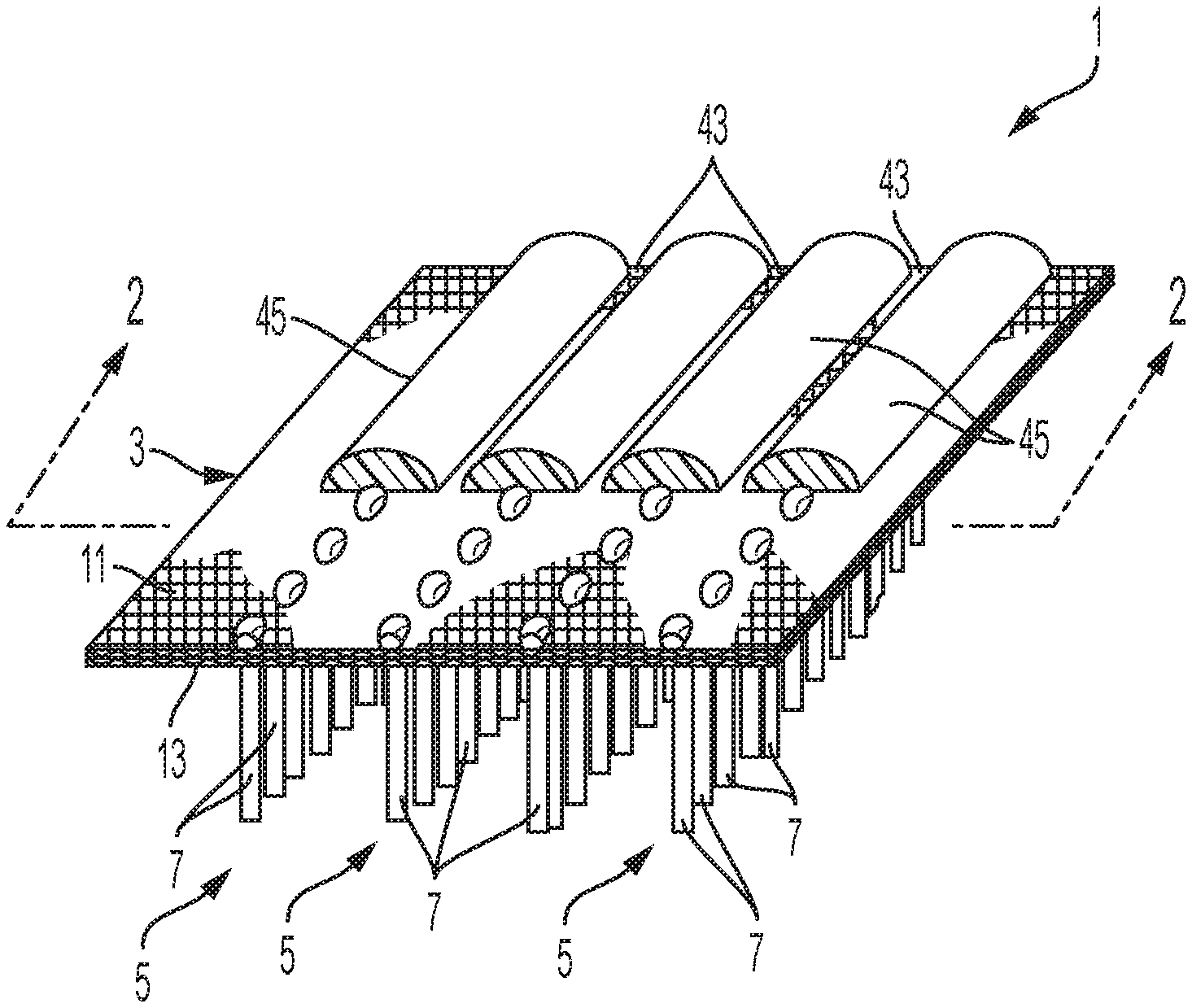
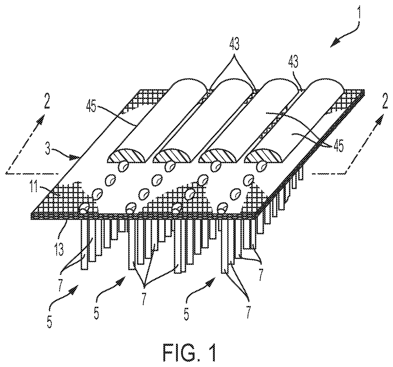
[0016] FIG. 1 illustrates a perspective view of an artificial surface of the present invention.
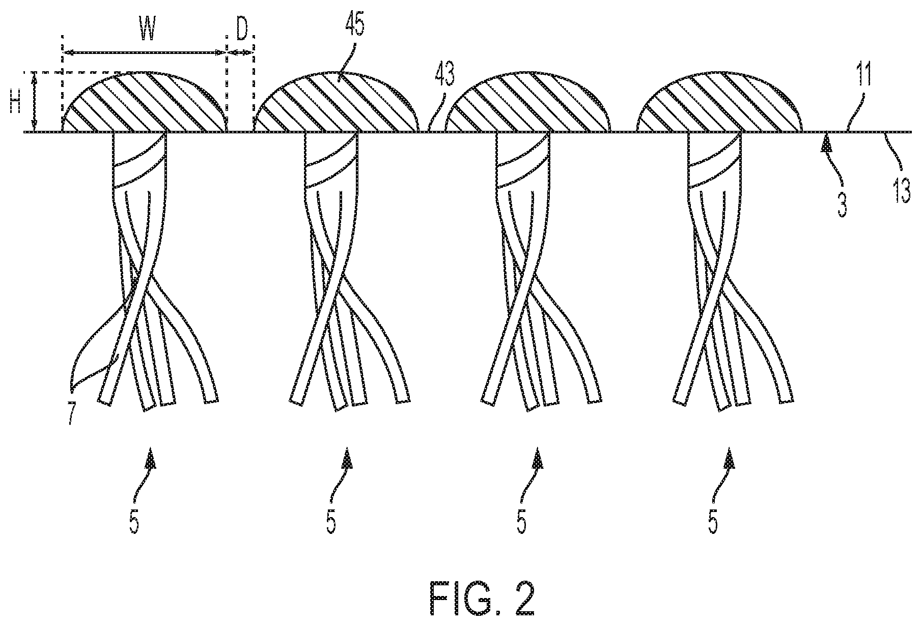
[0017] FIG. 2 illustrates a cross-section view taken along line 2-2 in FIG. 1.
DETAILED DESCRIPTION OF THE INVENTION
[0018] The present system and method will be described in connection with the figures, it being understood that the description and figures are for illustrative, non-limiting purposes.
[0019] Systems, methods, and structures are provided that integrate shock absorption into manufactured artificial turf that can be laid on a field for forming an artificial turf field as part of an overall artificial turf system for a field. During the manufacture of artificial turf, a foam adhesive, such as frothed polyurethane foam can be deposited to the backing along the row of artificial fiber. The foam can integrate adhesive and shock absorption into the artificial turf that can bind to the backing to hold the artificial turf fibers and attach a deposit of the foam material having the physical characteristics to absorb shock from foot traffic or use of the surface, per for example a specified requirement (e.g., standard shock absorption requirements). The shock absorbing characteristic can reduce or eliminate the need for other forms of shock absorbing solutions in artificial turf installations such as underlying shock absorbing panels and/or infill particles that provide shock absorption to the artificial turf system. The rows or deposits of artificial (contemplating configurations other than rows) are configured on the backing to be spaced apart. The spacing is configured to be sufficient to allow for drainage of water in expected field applications through water permeable areas of the backing, which may be from punctured holes, weaved surface of backing without any adhesive or other treatment to block water, or other form of water permeability. The approach can for example reduce time and cost which can significantly advantage the installer and customer. The deposited material can be an adhesive that is deposited directly on the backing of the artificial turf (e.g., the weaved material substrates through which artificial turf ribbons are tufted) and can adhesive can adhere directly to the backing (and/or the material of the fibers). This can for example include first deposit of adhesive directly on the material to be bound and a second deposition directly on top of the first deposit.
[0020] Embodiments of the present invention disclose a shock absorbing artificial surface. The shock absorbing artificial surface comprises a flexible, porous, backing member and parallel rows of ribbons projecting through and upwardly from the backing member. The shock absorbing artificial surface further comprises parallel rows of shock absorbing material on the backside of the backing member overlying the rows of ribbons. Overlying the rows of ribbons refers to the relative position of the shock absorbing material with a reference point of the surface being viewed for a side where the surface is horizontal and the shock absorbing material is on the top and the fibers on the direct opposite side (visually extending down). When, for example, the surface is installed the shock absorbing material will be underlying the rows of ribbons (e.g., a row of shock absorbing material is directly corresponding and generally aligned and underlying a row of ribbon).
[0021] The present technology described in embodiments of the invention meets and maintains industry/FieldTurf standard requirements for drainage. The froth/foam line technology is expected to supply improvement in surface hardness and provide the necessary level of shock absorbance (e.g., the same or substantially the same as the shock pad) with or without other elements that are provided as a part of the structure that provides shock absorbance such as the infill particles. Thus, the artificial turf can be installed without a separate shock pad layer conventionally placed underneath the turf to absorb shock forces, or the artificial turf can consist essentially of backing, shock absorbing bumps adhered to the backing, turf fibers, and infill particles. Accordingly, the ground does not need to be groomed to be flat, which is conventionally required before installing the shock pad layer on the ground. Embodiments of the invention provide that when the artificial turf is laid over the ground, the compression from the weight of structure results in such a flat surface to the view of the eye and physical landing of shoes of players (e.g., no special grooming to the ground is needed to adjust for the existence of the bumps). The flatness and texture of the artificial turf described herein is the same or substantially the same to players.
[0022] As shown in FIG. 1, the surface 1 has a thin, flexible, backing member 3 with parallel rows 5 of strips or ribbons 7 projecting upwardly from the backing member 3. The flexible, backing member 3 comprises two backing layers 11, 13. The bottom layer 11 can be a woven or needle punched polypropylene fabric. The top layer 13 can be also a woven or needle punched polypropylene fabric. Other suitable polymers can be used for the bottom layer 11 and the top layer 13. The plastic strips or ribbons 7 are tufted through the backing member 3 passing through both layers. In some embodiments, a relatively thick layer of infilled particulate material can be provided on the backing member 3 supporting the ribbons 7 in a relatively upright position on the backing member 3.
[0023] While the backing member 3 has been shown as comprising two layers, it can also be formed from one layer or more. One or more of the layers in the backing member 3 can be a needle punched woven fabric to provide better drainage, the fabric being relatively thick if used only as a single layer. At least one of the layers 11 in the backing member 3 can be needle punched with synthetic, fuzzy fibers to provide means to wick moisture through the layer. The fuzzy fibers further improve drainage of the surface.
[0024] The ribbons 7 are made from suitable synthetic plastic material which is extruded in a strip that is relatively wide and thin. The preferred plastic material is polyethylene which is soft and has good abrasion resistance. Polypropylene can also be used in making the ribbons. The strip can have a width ranging between about a half inches and about one and a half inches but is preferably around about one-half inch wide. The thickness of the strip ranges between 65 microns and 150 microns. The ribbons 7 are cut from the extruded strip and fastened by tufting in the backing member 3 in parallel rows 5. Between 2 to 8 tufts are formed per inch of row with 4 tufts per inch being preferable. The strips are mechanically fibrillated or split to about one-eighth of an inch or more. The fibrillation, which is done mechanically during the manufacturing of the strip, provides a ribbon which resembles a hair net, that is, the resulting fibers are interconnected.
[0025] The spacing of the rows of ribbons is dependent on the activity to be performed on the field. For instance, cleats worn on the shoes of athletes for different sports have a spacing on the average of about three-quarters of an inch. Football cleats or soccer cleats may be wider than baseball cleats. The spacing is in relation to the type of sport to be played on the field and is a consequence of the spacing of the cleats on the shoes of the players. Likewise, in sports such as horse racing, it is contemplated that much wider spacing will be required between the rows to accommodate the wider hooves of the horses.
[0026] The layer of particulate material, for example, comprises a mixture of a hard sand, such as silica, and cryogenically ground crumb rubber. The particles can range in size between four mesh and seventy mesh, but preferably are between fifteen and thirty mesh for sports where abrasion of the players contacting the surface is a factor and between four and thirty mesh where abrasion is not a factor. The silica sand could be replaced by graded small rocks, hard and heavy granulated plastics, or other hard sand. The cryogenically ground crumb rubber could be replaced by other resilient materials, such as cork, styrene, EPDM rubber, neoprene, or other similar materials, if the particulate shape equates the shape of cryogenically ground rubber. In some cases, some or all of the resilient material could be replaced by other materials which perform specific roles. An example would be using perlite to replace the resilient material so as to reduce compaction and possibly absorb moisture.
[0027] The mix of sand and resilient material can vary depending on the end use of the surface. More rubber is used if the surface requires more resiliency. In relatively thick surfaces the layer of particulate material can be divided in sub-layers with the lower sub-layer adjacent the backing member 3, having smaller particles and the upper sub-layer having larger particles to initiate good drainage. The particles in the lower sub-layer could be mainly sand with a mesh size of about forty to seventy mesh. The upper sub-layer would comprise larger particles of sand combined with the rubber particles. Using mainly, or only, sand in the lower layer reduces the cost of the surface.
[0028] The artificial or synthetic surface 1 is manufactured by attaching the ribbons 7 by tufting them through the backing member 3 in rows 5. Once the ribbons 7 are tufted in place, the backing member 3 can be coated as described herein on its back side to adhere the ribbons to the backing member.
[0029] Preferably, in one embodiment of this invention, using a porous backing member, only portions of the backing member are coated to provide better drainage and to reduce costs. In accordance with this embodiment, the backing member 3, after the ribbons 7 have tufted in place, is passed, upside down, through a coating machine. Conventional coating methods can be applied to the present invention. For example, a portion 43 of the back side 11 of the backing member 3 not overlying the parallel rows 5 of ribbons 7 is covered by an array of parallel fingers. Applicator means are provided for applying or depositing shock absorbing material "M" onto the back side of the backing member. The shock absorbing material "M" is then spread and laid down against the parallel rows 5 of ribbon ends without coating the portion 43.
[0030] The shock absorbing material "M" forms strips or bumps 45 of shock absorbing material "M" covering the ribbon rows 5, but adjacent areas 43 of backing member 3 are uncovered, because of the fingers, to provide a very porous surface which easily drains. While each of the shock absorbing material "M" strips or bumps 45 covers or overlies a single row of the ribbon rows 5 in FIG. 1, it is also possible for each of the strips or bumps 45 to cover or overlie more than one single row of the ribbon rows 5. For example, in some embodiments, the strips or bumps 45 cover or overlie two rows of the ribbon rows 5.
[0031] The ribbon ends in these rows are covered with shock absorbing material "M" to adhere the ribbons 7 to the backing member 3. Because the shock absorbing material "M" is an adhesive material, no additional adhesive may be applied between the parallel rows of shocking absorbing material and the back of backing member. In preferred embodiments, the adhesive material is a foam including a mechanically frothed foam comprising polyether, polyurethane, polyester polyurethane, latex, or mixtures thereof. The material sufficiently holds the ribbons 7 in place for an extended period (e.g. a number of years) of being subject to foot traffic or game play.
[0032] The adhesive froth/foam coating row can be made using a two-part polyurethane system or single part latex system with injected N.sub.2 or compressed air to attain the desired froth/foam density. As will be understood by a person skilled in the art of synthetic grass surfaces, a wide variety of methods of manufacturing the froth/foam coating row are possible. In other embodiments, there can be two or more layers of adhesive. For example, a first layer and one or more bump layers over it can be provided. The multiple layers can be integrated into a single step or component. Conventional adhesives applied to the backing member to adhere to tufts are not capable of absorbing and dissipating forces experienced on the surface of infilled artificial turf while adhesives disclosed in embodiments of the past invention are configured to both adhere to tufts and absorb and dissipate such forces. The fingers 37 prevent shock absorbing material "M" from covering the narrow areas 43 of the backing member 3 adjacent the ribbon rows 5.
[0033] While one form of applying or depositing the coating in strips on the rows of ribbons has been described, the coating could be applied by other means. For example, a series of nozzles could apply thin lines of coatings onto the rows of ribbons and a doctor blade could flatten the lines of coating onto the back of the mat while leaving relative wide, elongated areas of the backing member uncoated and thus capable of fast drainage. The coating process can be modified to allow simultaneous control over both height and width of strips or bumps 45.
[0034] As shown in FIG. 2, each of the parallel rows of strips or bumps 45 of shock absorbing material is half-cylinder shaped, dome shaped, or in any shape facilitating shock absorption. Preferably, each of the parallel rows of strips or bumps 45 of shock absorbing material may have a height that is sufficient to completely encapsulate the height of the tufted ribbons making the ribbons invisible after coating. Preferably, the height is between about 4 mm and about 15 mm. Alternatively, each of the parallel rows of strips or bumps 45 of shock absorbing material may partially encapsulate the height of the tufted ribbons making the ribbons visible.
[0035] Each of the parallel rows of strips or bumps 45 of shock absorbing material may have a width such that the strips or bumps 45 do not impede drainage. Preferably, the width is between about 0.5 inches and about 1.5 inches. The strips or bumps 45 may be spaced apart across the adjacent areas 43 of backing member 3 by an uncoated gap between about 0.1 inches and about 0.3 inches. Alternatively, the parallel rows of shock absorbing material may not be spaced apart. If not spaced apart, the strips or bumps 45 can be punctured or holed to allow for drainage. The arrangement of the half-cylinder shaped or dome shaped strips or bumps 45 ensures that separation between adjacent bumps is always provided.
[0036] While each of the shock absorbing material "M" strips or bumps 45 covers or overlies a single row of the ribbon rows 5 in FIG. 2, it is also possible for each of the strips or bumps 45 to cover or overlie more than one single row of the ribbon rows 5. For example, in some embodiments, the strips or bumps 45 cover or overlie two rows of the ribbon rows 5.
[0037] Different types of bumps and arrangements can be made. The dimensions, spacing, or frequency of the bumps (i.e. tuft gauge) and the dimensions, weight and composition of the infill materials are controllable. The use of the frequency of bumps (i.e. tuft gauge), the weight of the infill material and dimensions of bumps, and the mechanical dampening responses of artificial tuft can be configured, and preferably the weight of infill, pile height, or combinations of two can be reduced (e.g., in comparison to conventional applications).
[0038] Certain known technology involved depositing an adhesive in rows on the backing to provide the binding to the rows of fibers, which is also involved here but that prior art approach involved simply a liquid flat deposit of the adhesive. This approach sought to create a generally flat backing. Embodiments of the present invention are directed to include an adhesive comprising the foamed material that adds height to the backing or projections that extend above the backing when formed and correspondingly creates valleys, which are not consistent with the "flat" approach of the above mentioned known design.
[0039] In implementation, embodiments of the present invention integrate adhesion (for the ribbons) and shock pad creation in the same or single step.
[0040] In some embodiments, the function of shock absorption that is a specific requirement for a particular field (e.g., there are different standards by sport) is provided only, substantially only, or substantially by the shock absorbing material attached to the back of the backing as part of the artificial turf system (the system meaning the overall system of turf and related components that is installed on a particular surface to provide the field and meet the various requirements). For example, shock absorbing material that is attached to the back, as per embodiments herein, provides 75% or more of the shock absorption functionality of the artificial turf system
[0041] In some embodiments, implementation can be with or without the installation of a shock pad that is rolled on the field or placed in panels as an underlayment before the artificial turf is rolled over the underlayment as part of the installation.
[0042] Other types of spacing are contemplated, for example, there can be abutting deposited material, followed by a break for water drainage, and another two abutting deposits.
[0043] In some embodiments, the deposited material that provides the integrated adhesive and mechanical dampening functions is made only from a single foamed adhesive. In some embodiments, the deposited material is substantially only or substantially made of the single foamed adhesive (e.g., frothed polyurethane foam). In some embodiments, over 75%, 80%, or 90% of the deposited material is the foamed adhesive (e.g., frothed polyurethane foam).
[0044] It should be understood that combinations of described features or steps are contemplated even if they are not described directly together or not in the same context.
[0045] It should be also contemplated that one skilled in the art would understand the present invention may not be limited only to the height and width of strips or bumps and distance therebetween described in the embodiments.
[0046] It should be understood that claims that include fewer limitations, broader claims, such as claims without requiring a certain feature or process step in the appended claim or in the specification, clarifications to the claim elements, different combinations, and alternative implementations based on the specification, or different uses, are also contemplated by the embodiments of the present invention.
[0047] The term "about" herein specifically includes .+-.10% from the indicated values in the range.
[0048] It should be understood that a reference to layer or deposited material does not necessarily mean that it is a single layer or material and/or there can be overlying or intermediary material.
[0049] Other terms or words that are used herein are directed to those of ordinary skill in the art in this field of technology and the meaning of those terms or words will be understood from terminology used in that field or can be reasonably interpreted based on the plain English meaning of the words in conjunction with knowledge in this field of technology. This includes an understanding of implicit features that for example may involve multiple possibilities, but to a person of ordinary skill in the art a reasonable or primary understanding or meaning is understood.
[0050] It should be understood that the above-described examples are merely illustrative of some of the many specific examples that represent the principles described herein. Clearly, those skilled in the art can readily devise numerous other arrangements without departing from the scope as defined by the following claims.
* * * * *
D00000
D00001
D00002
XML
uspto.report is an independent third-party trademark research tool that is not affiliated, endorsed, or sponsored by the United States Patent and Trademark Office (USPTO) or any other governmental organization. The information provided by uspto.report is based on publicly available data at the time of writing and is intended for informational purposes only.
While we strive to provide accurate and up-to-date information, we do not guarantee the accuracy, completeness, reliability, or suitability of the information displayed on this site. The use of this site is at your own risk. Any reliance you place on such information is therefore strictly at your own risk.
All official trademark data, including owner information, should be verified by visiting the official USPTO website at www.uspto.gov. This site is not intended to replace professional legal advice and should not be used as a substitute for consulting with a legal professional who is knowledgeable about trademark law.