Durable Oxygen Evolution Electrocatalysts
Takanabe; Kazuhiro ; et al.
U.S. patent application number 16/648794 was filed with the patent office on 2020-10-01 for durable oxygen evolution electrocatalysts. The applicant listed for this patent is King Abdullah University of Science and Technology. Invention is credited to Keisuke Obata, Kazuhiro Takanabe.
| Application Number | 20200308720 16/648794 |
| Document ID | / |
| Family ID | 1000004913657 |
| Filed Date | 2020-10-01 |


View All Diagrams
| United States Patent Application | 20200308720 |
| Kind Code | A1 |
| Takanabe; Kazuhiro ; et al. | October 1, 2020 |
DURABLE OXYGEN EVOLUTION ELECTROCATALYSTS
Abstract
Oxygen evolution electrocatalysts, electrodes using oxygen evolution electrocatalysts, and methods of making oxygen evolution electrocatalysts are provided. The oxygen evolution electrocatalyst includes an oxide electrocatalyst and a permselective amorphous layer deposited on the oxide electrocatalyst. In this regard, the permselective amorphous layer may prevent diffusion of redox ions but permit diffusion of hydroxide ions and evolved O2 through the permselective amorphous layer.
| Inventors: | Takanabe; Kazuhiro; (Thuwal, SA) ; Obata; Keisuke; (Thuwal, SA) | ||||||||||
| Applicant: |
|
||||||||||
|---|---|---|---|---|---|---|---|---|---|---|---|
| Family ID: | 1000004913657 | ||||||||||
| Appl. No.: | 16/648794 | ||||||||||
| Filed: | September 19, 2018 | ||||||||||
| PCT Filed: | September 19, 2018 | ||||||||||
| PCT NO: | PCT/IB2018/057212 | ||||||||||
| 371 Date: | March 19, 2020 |
Related U.S. Patent Documents
| Application Number | Filing Date | Patent Number | ||
|---|---|---|---|---|
| 62560438 | Sep 19, 2017 | |||
| 62565732 | Sep 29, 2017 | |||
| 62626963 | Feb 6, 2018 | |||
| Current U.S. Class: | 1/1 |
| Current CPC Class: | C25B 11/0452 20130101; C25B 1/04 20130101; C25B 11/0415 20130101; C25B 11/0478 20130101 |
| International Class: | C25B 11/04 20060101 C25B011/04; C25B 1/04 20060101 C25B001/04 |
Claims
1. An oxygen evolution electrocatalyst comprising: an oxide electrocatalyst; and a permselective amorphous layer deposited on the oxide electrocatalyst, wherein the permselective amorphous layer prevents diffusion of redox ions but permits diffusion of hydroxide ions to the oxide electrocatalyst.
2. The oxygen evolution electrocatalyst according to claim 1, wherein the oxide electrocatalyst comprises an oxide of a transition metal.
3. The oxygen evolution electrocatalyst according to claim 1, wherein the oxide electrocatalyst comprises at least one of NiO.sub.x CoO.sub.x, FeO.sub.x, MnO.sub.x, IrO.sub.x, RuO.sub.x, or any combination thereof to form a mixed oxide.
4. The oxygen evolution electrocatalyst according to claim 1, wherein the oxide electrocatalyst comprises NiFeO.sub.x or CoFeO.sub.x.
5. (canceled)
6. The oxygen evolution electrocatalyst according to claim 1, wherein the permselective amorphous layer comprises a catalytically inactive material.
7. The oxygen evolution electrocatalyst according to claim 1, wherein the permselective amorphous layer comprises at least one of CeO.sub.x, TiO.sub.x, AlO.sub.x, ZnO.sub.x, ZrO.sub.x, SiO.sub.x, CaO.sub.x, MgO.sub.x, or any combination thereof.
8. The oxygen evolution electrocatalyst according to claim 1, wherein the permselective amorphous layer comprises CeO.sub.x; wherein the permselective amorphous layer comprises a thickness from about 100 nm to about 600 nm; and/or wherein the permselective amorphous layer is deposited approximately uniformly on the oxide electrocatalyst.
9. (canceled)
10. (canceled)
11. An electrode comprising: a substrate; and an oxygen evolution electrocatalyst, the oxygen evolution electrocatalyst comprising: an oxide electrocatalyst; and a permselective amorphous layer disposed on the oxide electrocatalyst, wherein the permselective amorphous layer prevents diffusion of redox ions but permits diffusion of hydroxide ions to the oxide electrocatalyst.
12. The electrode according to claim 11, wherein the substrate comprises a conductive substrate.
13. The electrode according to claim 11, wherein the substrate comprises at least one of cobalt, gold, nickel, a fluorine-doped tin oxide (FTO) substrate, a gold-coated FTO substrate or any combination thereof and optionally, wherein the oxide electrocatalyst comprises an oxide of a transition metal.
14. (canceled)
15. (canceled)
16. The electrode according to claim 11, wherein the oxide electrocatalyst comprises at least one of NiO.sub.x, CoO.sub.x, FeO.sub.x, MnO.sub.x, IrO.sub.x, RuO.sub.x, or any combination thereof to form a mixed oxide.
17. The electrode according to claim 11, wherein the oxide electrocatalyst comprises NiFeO.sub.x or CoFeO.sub.x.
18. (canceled)
19. The electrode according to claim 11, wherein the permselective amorphous layer comprises a catalytically inactive material.
20. The electrode according to claim 11, wherein: (i) the permselective amorphous layer comprises at least one of CeO.sub.x, TiO.sub.x, AlO.sub.x, ZnO.sub.x, ZrO.sub.x, SiO.sub.x, CaO.sub.x, MgO.sub.x, or any combination thereof; (ii) permselective amorphous layer comprises a thickness from about 100 nm to about 600 nm and/or the permselective amorphous layer is deposited approximately uniformly on the oxide electrocatalyst.
21. The electrode according to claim 11, wherein the permselective amorphous layer comprises CeO.sub.x.
22. (canceled)
23. (canceled)
24. A method of making an oxygen evolution electrocatalyst, the method comprising: providing an oxide electrocatalyst; and depositing a permselective amorphous layer on the oxide electrocatalyst via anodic deposition, wherein the permselective amorphous layer prevents diffusion of redox ions but permits diffusion of hydroxide ions to the oxide electrocatalyst.
25. The method according to claim 24, wherein depositing the permselective amorphous layer comprises depositing the permselective amorphous layer approximately uniformly on the oxide electrocatalyst.
26. The method according to claim 24, wherein the oxide electrocatalyst comprises an oxide of a transition metal.
27. The method according to claim 24, wherein the oxide electrocatalyst comprises at least one of NiO.sub.x, CoO.sub.x, FeO.sub.x, MnO.sub.x, IrO.sub.x, RuO.sub.x, or any combination thereof to form a mixed oxide.
28. The method according to claim 24, wherein: (i) the oxide electrocatalyst comprises NiFeO.sub.x or CoFeO.sub.x; ii) the permselective amorphous layer comprises at least one of CeO.sub.x, TiO.sub.x, AlO.sub.x, ZnO.sub.x, ZrO.sub.x, SiO.sub.x, CaO.sub.x, MgO.sub.x, or any combination thereof; and/or (iii) the permselective amorphous layer comprises CeO.sub.x.
29. (canceled)
30. (canceled)
31. (canceled)
Description
CROSS-REFERENCED TO RELATED APPLICATIONS
[0001] This application claims the benefit of and priority to U.S. Provisional Application No. 62/560,438, filed Sep. 19, 2017, 62/565,732, filed Sep. 29, 2017, and 62/626,963 filed Feb. 6, 2018, which are hereby incorporated herein by reference in their entirety.
TECHNICAL FIELD
[0002] The presently-disclosed invention relates generally to providing stable and selective electrocatalysts for use in the oxygen evolution reaction, and more particularly to oxygen evolution electrocatalysts, electrodes using oxygen evolution electrocatalysts, and methods of making oxygen evolution electrocatalysts.
BACKGROUND
[0003] Hydrogen is one of the energy carriers that can effectively store intermittent energy from renewables, such as solar and wind power. A lot of techniques are studied to generate hydrogen and oxygen from water via, for example, water electrolysis and photocatalytic water splitting. Since the oxygen evolution reaction (OER) is a kinetically sluggish reaction compared with the hydrogen evolution reaction (HER) in water splitting, the development of highly active, durable and cost-effective electrocatalysts for OER is desired. NiFeO.sub.x is one of the most active electrocatalysts towards OER in alkaline conditions and it is known that Fe has a critical role to improve activity while the reason why doping of Fe boosts the kinetics of OER is still under discussion. Although a lot of research has been devoted to decrease overpotential via development of layered double hydroxide (LDH) structure, compositional control, or deposition on conductive support with high surface area, the stability of NiFeO.sub.x under harsh oxidative conditions has not been considered. Indeed, the efforts relating to decreasing overpotential to date have resulted in either increased overpotential or decreased iron content in the electrocatalyst during a stability test.
[0004] Accordingly, there still exists a need for an electrocatalyst that provides improved stability and selectivity in the oxygen evolution reaction (OER).
BRIEF SUMMARY OF THE INVENTION
[0005] One or more embodiments of the invention may address one or more of the aforementioned problems. Certain embodiments provide oxygen evolution electrocatalysts, electrodes using oxygen evolution electrocatalysts, and methods of making oxygen evolution electrocatalysts. In one aspect, an oxygen evolution electrocatalyst is provided. The oxygen evolution electrocatalyst may include an oxide electrocatalyst, and a permselective amorphous layer deposited on the oxide electrocatalyst. The permselective amorphous layer may prevent diffusion of redox ions but permit diffusion of hydroxide ions to the oxide electrocatalyst.
[0006] In another aspect, an electrode using an oxygen evolution electrocatalyst is provided. The electrode may include a substrate and an oxygen evolution electrocatalyst. The oxygen evolution electrocatalyst may include an oxide electrocatalyst, and a permselective amorphous layer deposited on the oxide electrocatalyst. The permselective amorphous layer may prevent diffusion of redox ions but permit diffusion of hydroxide ions to the oxide electrocatalyst.
[0007] In yet another aspect, a method of making an oxygen evolution electrocatalyst is provided. The method may include providing an oxide electrocatalyst, and depositing a permselective amorphous layer on the oxide electrocatalyst via anodic deposition. The permselective amorphous layer may prevent diffusion of redox ions but permit diffusion of hydroxide ions to the oxide electrocatalyst.
BRIEF DESCRIPTION OF THE DRAWING(S)
[0008] Having thus described the invention in general terms, reference will now be made to the accompanying drawings, which are not necessarily drawn to scale, and wherein:
[0009] FIG. 1a illustrates results from electrocatalytic stability tests on electrocatalysts in accordance with certain embodiments of the invention.
[0010] FIGS. 1b and 1c are cyclic voltammograms of electrodes in accordance with certain embodiments of the invention.
[0011] FIG. 1d is a Tafel plot taken from the cyclic voltammograms of FIGS. 1b and 1c.
[0012] FIGS. 2a and 2b are scanning electron microscope (SEM) images of electrocatalysts in accordance with certain embodiments of the invention.
[0013] FIG. 2c is an SEM image of an electrode in accordance with certain embodiments of the invention.
[0014] FIG. 2d is a Raman spectra of electrodes in accordance with certain embodiments of the invention.
[0015] FIG. 3a illustrates Nyquist plots of electrocatalysts in accordance with certain embodiments of the invention.
[0016] FIG. 3b illustrates Bode plots of electrocatalysts in accordance with certain embodiments of the invention.
[0017] FIG. 4a illustrates cyclic voltammograms for electrodes in accordance with certain embodiments of the invention.
[0018] FIG. 4b illustrates Faradaic efficiency of oxygen during controlled current electrolysis for electrocatalysts in accordance with certain embodiments of the invention.
[0019] FIGS. 5a and 5b are cyclic voltammograms for substrates and electrodes in accordance with certain embodiments of the invention.
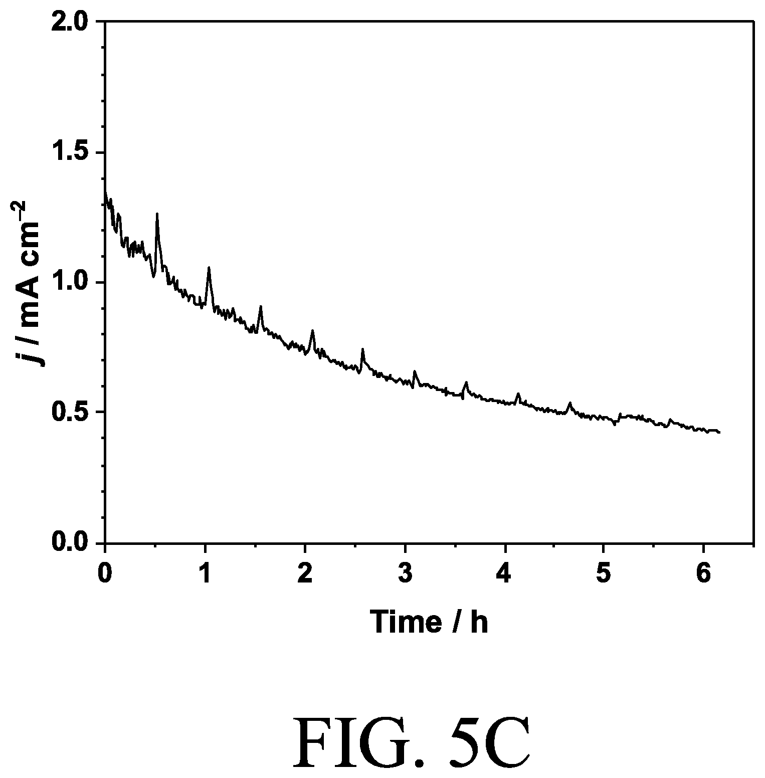
[0020] FIG. 5c is a chronoamperogram of an electrode in accordance with certain embodiments of the invention.
[0021] FIG. 6 illustrates peak position of Ni reduction peaks taken from FIGS. 1b and 1c.
[0022] FIG. 7 illustrates XRD diffractograms of various substrates in accordance with certain embodiments of the invention.
[0023] FIGS. 8a and 8b are XPS spectra of the CeOx layer in accordance with certain embodiments of the invention.
[0024] FIGS. 9a and 9b illustrate equivalent circuits for (a) Randles circuit and (b) Voigt circuit in accordance with certain embodiments of the invention.
[0025] FIG. 10 is a cyclic voltammogram of electrodes in accordance with certain embodiments of the invention.
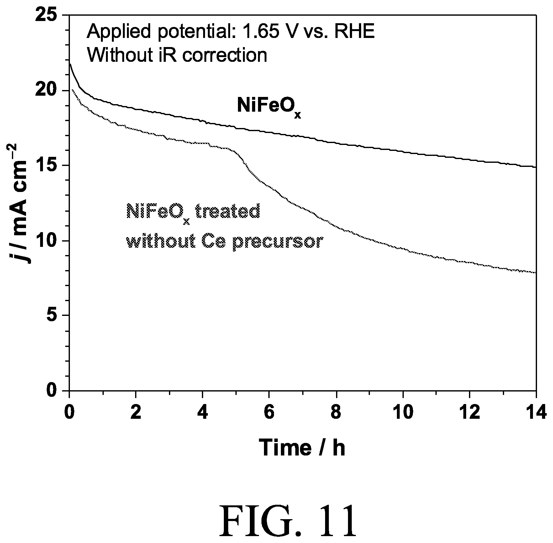
[0026] FIG. 11 is a chronoamperogram of electrocatalysts in accordance with certain embodiments of the invention.
[0027] FIG. 12a is a chronoamperogram of electrocatalysts in accordance with certain embodiments of the invention.
[0028] FIG. 12b illustrates electrocatalytic stability test results for electrodes in accordance with certain embodiments of the invention.
[0029] FIGS. 13a-13e illustrate Faradaic efficiency of oxygen during controlled current electrolysis for electrodes in accordance with certain embodiments of the invention.
[0030] FIG. 14 illustrates electrocatalytic stability test results for electrodes in accordance with certain embodiments of the invention.
[0031] FIGS. 15A and 15B illustrates cyclic voltammograms of electrodes in accordance with certain embodiments of the invention.
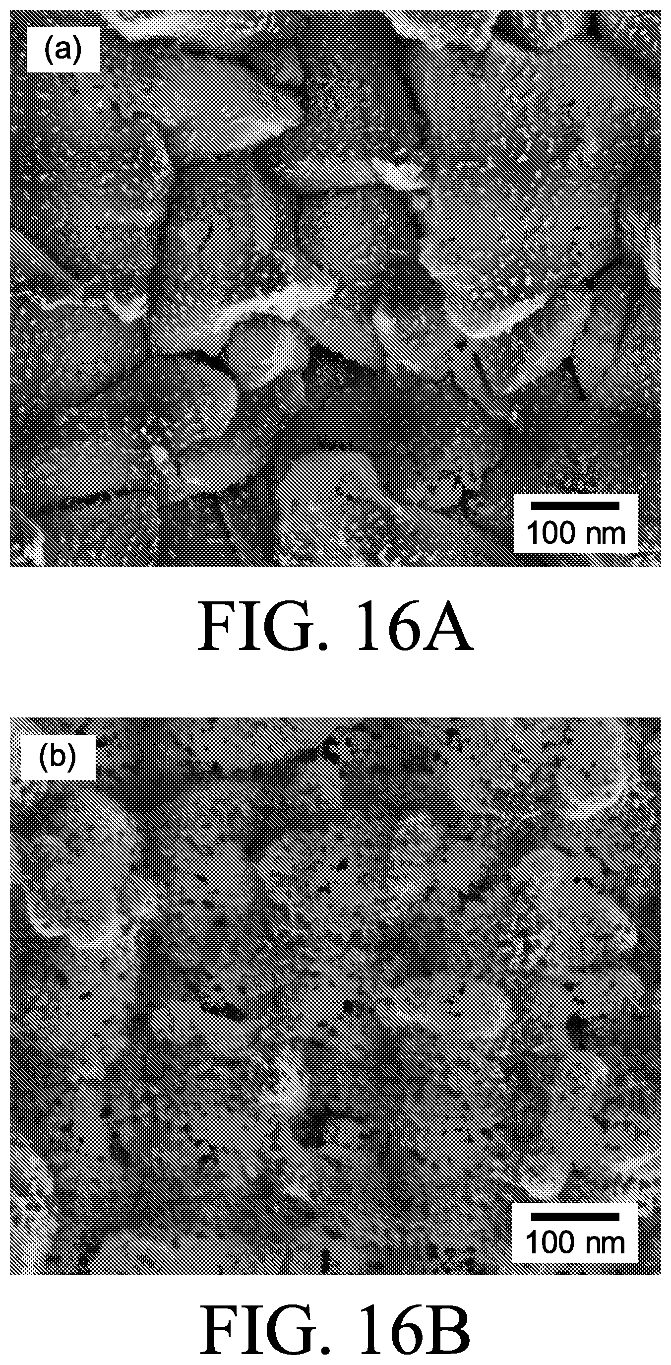
[0032] FIGS. 16a and 16b are SEM images of electrodes in accordance with certain embodiments of the invention.
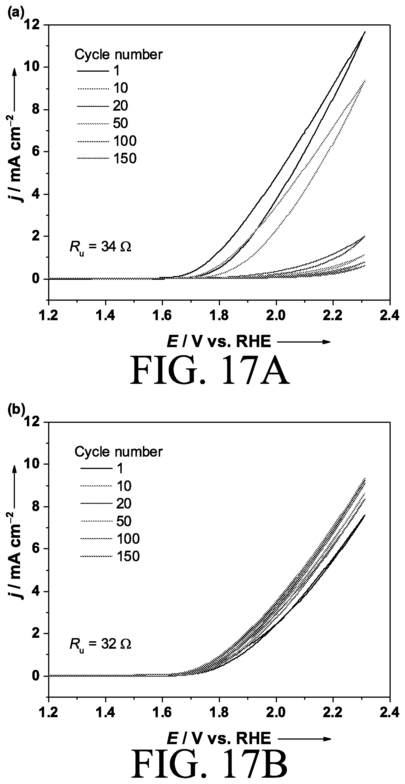
[0033] FIGS. 17a and 17b are cyclic voltammograms of electrodes in accordance with certain embodiments of the invention.
[0034] FIG. 18 is a schematic block diagram illustrating a method of making an oxygen evolution electrocatalyst in accordance with certain embodiments of the invention.
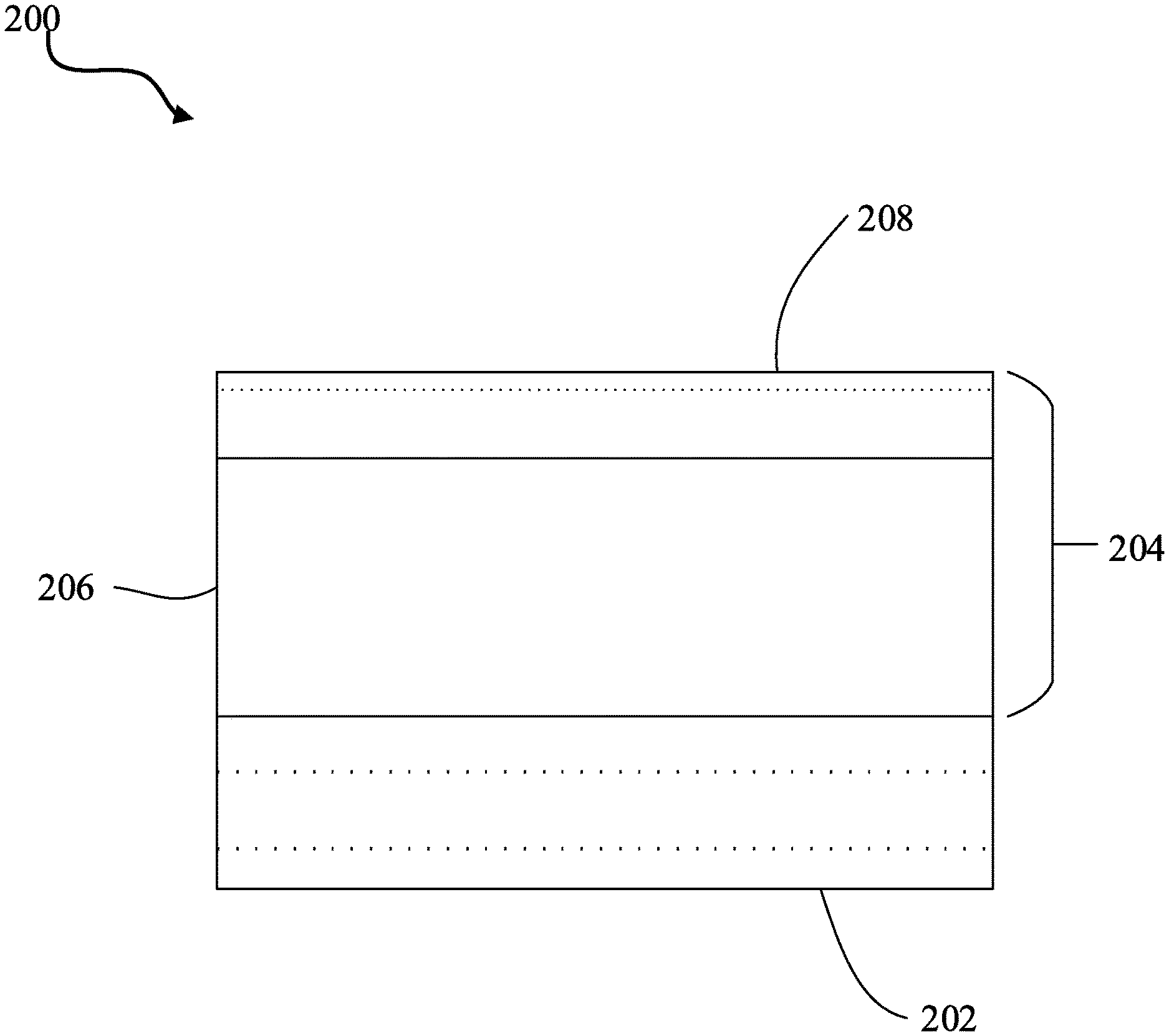
[0035] FIG. 19 illustrates a cross-section of an electrode in accordance with certain embodiments of the invention.
DETAILED DESCRIPTION
[0036] The invention now will be described more fully hereinafter with reference to the accompanying drawings, in which some, but not all embodiments of the inventions are shown. Indeed, this inventions may be embodied in many different forms and should not be construed as limited to the embodiments set forth herein; rather, these embodiments are provided so that this disclosure will satisfy applicable legal requirements. Like numbers refer to like elements throughout. As used in the specification, and in the appended claims, the singular forms "a", "an", "the", include plural referents unless the context clearly dictates otherwise.
[0037] Through combined effort and ingenuity, the inventors have developed a highly durable OER electrocatalyst by deposition of a permselective amorphous layer on an oxide electrocatalyst. The permselective amorphous layer includes a mixed oxide and hydroxide layer which prevents diffusion of redox ions while allowing OH.sup.- and evolved O.sub.2 to permeate through. Improved stability of the oxide electrocatalyst can be attributed to the permselectivity of the amorphous layer, which can regulate diffusion of redox anions, such as iodide, ferrocyanide and ferrate, between the electrolyte and oxide electrocatalyst. In this regard, the oxygen evolution electrocatalyst is a highly active and durable OER catalyst that undergoes harsh oxidative condition.
I. Oxygen Evolution Electrocatalyst
[0038] In accordance with certain embodiments, oxygen evolution electrocatalysts are provided. The oxygen evolution electrocatalyst includes an oxide electrocatalyst and a permselective amorphous layer deposited on the oxide electrocatalyst. In this regard, the permselective amorphous layer may prevent diffusion of redox ions (e.g., iodide, ferrocyanide, ferrate, etc.) but permit diffusion of hydroxide ions and evolved O.sub.2 through the permselective amorphous layer. Without intending to be bound by theory, the diffusion of hydroxide ions to the oxide electrocatalyst under the permselective amorphous layer allows the evolution of oxygen in the OER while preventing diffusion and further dissolution of easily-dissolved iron species from the underlying oxide to the electrolyte. Accordingly, the resulting oxygen evolution electrocatalyst described herein may achieve significantly improved stability over bare electrocatalysts (i.e. electrocatalysts without the permselective amorphous layer).
[0039] In accordance with certain embodiments, for example, the oxide electrocatalyst may comprise an oxide of a transition metal. In some embodiments, for instance, the oxide electrocatalyst may comprise at least one of NiO.sub.x, CoO.sub.x, FeO.sub.x, MnO.sub.x IrO.sub.x, RuO.sub.x, or any combination thereof to form a mixed oxide, where "x" is the number of oxygen atoms in the oxide electrocatalyst and may depend on the number of metal cations present, the number of oxidation states, and/or the like as understood by one of ordinary skill in the art. For example, in some embodiments, "x" may be from 2-8, and in further embodiments, "x" may be from 2-4. In certain embodiments, the oxide electrocatalyst may comprise NiFeO.sub.x. In other embodiments, for instance, the oxide electrocatalyst may comprise CoFeO.sub.x. In some embodiments, for example, the oxide electrocatalyst may comprise a thickness from about 10 nm to about 300 nm. By way of example only, the thickness of the CoO.sub.x electrocatalyst of FIG. 16A is about 10 nm, while the thickness of the NiFeO.sub.x electrocatalyst of FIG. 2C is about 300 nm.
[0040] According to certain embodiments, for instance, the oxide electrocatalyst may comprise an LDH structure or an amorphous structure. In further embodiments, for example, the oxide electrocatalyst may comprise a spinel composition. Spinels are a mineral oxide having the general formula of AB.sub.2O.sub.4 and may be supported on a plurality of support oxides. As such, the A component is tetrahedrally coordinated with the oxygens and the B component is octahedrally coordinated with the oxygens. Spinels may include a transition metal (e.g., iron (Fe), manganese (Mn), nickel (Ni), cobalt (Co), copper (Cu), vanadium (V), silver (Ag), titanium (Ti), etc.) and an "other metal" (i.e., aluminum (Al), magnesium (Mg), gallium (Ga), tin (Sn), thallium (Tl), lead (Pb), bismuth (Bi), or indium (In)).
[0041] In some embodiments, for example, a spinel composition may include copper, nickel, cobalt, iron, manganese, or chromium at any concentration, including quaternary, ternary, and binary combinations thereof. Ternary combinations may include Cu--Mn--Fe, Cu--Mn--Co, Cu--Fe--Ni, Cu--Co--Fe, Cu--Mn--Ni, Cu--Mn--Co, and Cu--Co--Ni. Binary combinations may include Cu--Mn, Cu--Fe, Cu--Co, Cu--Ni, Cu--Ni, Mn--Fe, Mn--Co, Mn--Ni, Co--Ni, and Co--Fe. In further embodiments, for instance, the oxide electrocatalyst may comprise one or more of CoFe.sub.2O.sub.4 and NiFe.sub.2O.sub.4.
[0042] In accordance with certain embodiments, for example, the permselective amorphous layer may comprise a catalytically inactive material. In some embodiments, for instance, the permselective amorphous layer may comprise at least one of CeO.sub.x, TiO.sub.x, AlO.sub.x, ZnO.sub.x, ZrO.sub.x, SiO.sub.x, CaO.sub.x, MgO.sub.x, or any combination thereof, where "x" is the number of oxygen atoms in the oxide electrocatalyst and may depend on the number of metal cations present, the number of oxidation states, and/or the like as understood by one of ordinary skill in the art. For example, in some embodiments, "x" may be from 2-8, and in further embodiments, "x" may be from 2-4. In further embodiments, for example, the permselective amorphous layer may comprise a thickness from about 100 nm to about 600 nm. In some embodiments, for instance, the permselective amorphous layer may comprise a thickness from about 100 nm to about 200 nm. If the thickness of the permselective amorphous layer is less than 100 nm, for example, the permselective amorphous layer begins to lose its selectivity. In certain embodiments, for instance, the permselective amorphous layer may be deposited approximately uniformly (i.e. homogenously) on the oxide electrocatalyst.
II. Electrode
[0043] In another aspect, electrodes using oxygen evolution electrocatalysts are provided. As shown in FIG. 19, the electrode 200 includes a substrate 202 and an oxygen evolution electrocatalyst 204. The oxygen evolution electrocatalyst 204 includes an oxide electrocatalyst 206 and a permselective amorphous layer 208 deposited on the oxide electrocatalyst 206. In this regard, the permselective amorphous layer may prevent diffusion of redox ions but permit diffusion of hydroxide ions to the oxide electrocatalyst, as previously discussed herein.
[0044] In accordance with certain embodiments, for example, the substrate may comprise any conductive substrate suitable for use with the oxygen evolution electrocatalyst as understood by one of ordinary skill in the art. In some embodiments, for instance, the substrate may comprise at least one of cobalt, gold, nickel, a fluorine-doped tin oxide (FTO) substrate, or any combination thereof. In further embodiments, for example, the substrate may comprise a gold-coated FTO substrate. By way of example only, approximately 200 nm of gold may be deposited on approximately 500 nm of FTO substrate; however, the substrate may comprise any thickness as long as it remains conductive.
III. Method of Making an Oxygen Evolution Electrocatalyst
[0045] In yet another aspect, methods of making oxygen evolution electrocatalysts are provided. As shown in FIG. 18, the method 100 includes providing an oxide electrocatalyst at block 101, and depositing a permselective amorphous layer on the oxide electrocatalyst via anodic deposition at block 102. In this regard, the permselective amorphous layer may prevent diffusion of redox ions but permit diffusion of hydroxide ions to the oxide electrocatalyst, as previously discussed herein.
[0046] In accordance with certain embodiments, for example, depositing the permselective amorphous layer may comprise depositing the permselective amorphous layer approximately uniformly on the oxide electrocatalyst. As mentioned herein, anodic deposition may be used to deposit the permselective amorphous layer on the oxide electrocatalyst. By way of example only, the anodic deposition may utilize an electrolyte (i.e. deposition solution) including from about 0.1 M to about 0.5 M Ce(NO.sub.3).sub.3.6H.sub.2O at room temperature. A constant anodic potential may be applied to the deposition solution, and the deposition solution may be bubbled with argon before adding metal salts, and the argon atmosphere may be maintained during anodic deposition.
EXAMPLES
[0047] The following examples are provided for illustrating one or more embodiments of the present invention and should not be construed as limiting the invention.
[0048] Material Preparation
[0049] Gold-coated fluorine-doped tin oxide (FTO) substrate was prepared by sputter-coating 20 nm of Ti followed by 190 nm of gold. Electrodeposition of NiFeO.sub.x on the gold-coated FTO substrate was performed by cathodic electrochemical deposition. -20 mA cm.sup.-2 was applied for 2 mM in an electrolyte solution containing 50 mM NH.sub.4OH, 25 mM H.sub.2SO.sub.4, 9 mM NiSO.sub.4.7H.sub.2O and 9 mM FeSO.sub.4.7H.sub.2O with a carbon paper as a counter electrode. The pH of the deposition solution was adjusted to 2.5. When NiFeCeO.sub.x was prepared, 3, 6 or 9 mM of Ce(NO.sub.3).sub.3.6H.sub.2O was also added to the deposition solution. A CeO.sub.x layer was formed on the NiFeO.sub.x electrode by anodic deposition in the electrolyte containing 0.4 M Ce(NO.sub.3).sub.3.6H.sub.2O and 0.4 M CH.sub.3COONH.sub.4. A constant anodic potential of 1.1 V vs Ag/AgCl was applied for 6 h with resting period of 1 mM in every 30 mM Deposition solution was stirred by a magnetic stir during deposition. pH of 0.4 M CH.sub.3COONH.sub.4 was adjusted to 8 by 4 M NaOH solution and it turned to pH 7 after adding Ce(NO).sub.3.6H.sub.2O. Deposition solutions were bubbled with Ar (99.9999%) for at least 30 mM before adding metal salts and Ar atmosphere was maintained during deposition.
[0050] Physical Characterization
[0051] X-ray diffraction (XRD) was collected with a Bruker D8 Advanced A25 diffractometer in the Bragg-Brentano geometry (with Cu K.alpha. radiation at 40 kV and 40 mA). Data sets were acquired in continuous scanning mode over a 20 range of 0-80.degree.. Raman spectra was obtained by an Olympus BXFMILHS microscope with a He/Ne laser, which has excitation at 633 nm. X-ray photoelectron spectroscopy (XPS) spectra were obtained with an AMICUL KRATOS using Al anode at 10 kV and 15 mA. A peak maximum of C 1S at 284.8 eV was used as an internal standard to correct the binding energies. To obtain loading of catalysts on the substrates, catalysts were dissolved in 1 mL of aqua regia for 12 h and then diluted in 9 mL of Milli-Q water. Induced coupled plasma (ICP) measurements were performed for the solutions using an ICP-OES Varian 72 ES. Scanning electron microscopy (SEM) images were obtained with Nova Nano 630 scanning electron microscope from FEI Company. Cross-section views were taken using an FBI Helios NanoLab 400S FIB/SEM dual-beam system equipped with a Ga.sup.+ ion source. The surfaces of the electrode were covered by C and Pt layers by electron and ion beam to protect the sample from the milling
[0052] Electrochemical Measurement
[0053] 1 M KOH solution (pH=14) and 0.5 M K.sub.0.6H.sub.2.4BO.sub.3 solution (pH=9.4) were prepared from KOH, H.sub.3BO.sub.4, and Milli-Q water (18 M.OMEGA. cm). Purification of 1 M KOH solution was conducted. Electrochemical measurements were performed using a BioLogic VMP3 potentiostat. Pt wire and Ni foam were used as counter electrodes in purified KOH and other solutions, respectively. Hg/HgO (1 M NaOH) (ALS CO., Ltd) and Ag/AgCl (Saturated KCl) (ALS CO., Ltd) were used as reference electrodes in KOH solution and KBi solution, respectively. All potentials are reported with respect to the reversible hydrogen electrode (RHE). Potentials were reported with iR-correction unless otherwise specified. Solution resistance R.sub.s was measured by impedance spectroscopy (100 mHz-10 kHz, 10 mV amplitude). Before and during all the measurements, Ar (99.9999%) or O.sub.2 (99.999%) gas was continuously supplied to the electrochemical cell. Product gas from gas tight cell was quantified with a gas chromatography (GC-8A; Shimadzu Co. Ltd.) equipped with a TCD detector and a Molecular sieve 5A column using Ar (99.999%) as a carrier gas. Ar was flowed at 22 SCCM in the electrochemical cell and outlet gas is connected to a sampling loop in the GC.
Example 1
[0054] NiFeO.sub.x was prepared on a Au/Ti/FTO substrate by cathodic deposition and used as a base electrode. The amorphous CeO.sub.x layer was formed on the NiFeO.sub.x by applying a constant anodic potential of 1.7 V vs. RHE in the deposition solution containing 0.4 M cerium nitrate and 0.4 M ammonium acetate (pH=7) for 6 h at room temperature. Without intending to be bound by theory, in the deposition solution, Ce.sup.3+ is oxidized and precipitates on the anode because of the lower solubility of Ce.sup.4+ compared to Ce.sup.3+. As shown in FIG. 5A, which is a cyclic voltammogram for Au/Ti/FTO in 0.4 M Ce(NO).sub.3+0.4 M CH.sub.3COONH.sub.4 (pH=7) under Ar atmosphere (condition: 20 mV s.sup.-1 and 298 K), oxidation of Ce.sup.3+ appeared around 1.0 V vs. RHE in the 1.sup.st cycle and disappeared from the 2.sup.nd cycle. Depending on the potential of the anode, Ce.sup.3+ can be also oxidized by O.sub.2 evolved from the anode and deposited on it. Because Ni(OH).sub.2 is not conductive but becomes conductive once it is oxidized to NiOOH, in order to deposit CeO.sub.x on top of the NiFeO.sub.x, more anodic potential was applied than the potential for oxidization of Ce.sup.3+ where oxygen can evolve, as shown in FIG. 5B, which is a cyclic voltammogram for an NiFeO.sub.x electrode in 0.4 M Ce(NO).sub.3+0.4 M CH.sub.3COONH.sub.4 (pH=7) under Ar atmosphere (condition: 20 mV s.sup.-1 and 298 K).
[0055] The bulk composition of electrodes were quantified by inductively coupled plasma (ICP), shown in Tables 1 and 2 below. Table 1 shows the composition of bare NiFeO.sub.x and CeO.sub.x/NiFeO.sub.x electrodes. Table 2 shows the composition of NiFeCeO.sub.x catalysts prepared by cathodic deposition in deposition solution containing 25 mM NH.sub.4SO.sub.4, 9 mM NiSO.sub.4, 9 mM FeSO.sub.4 and x mM Ce(NO.sub.3).sub.3.
TABLE-US-00001 TABLE 1 Ni/.mu.mol Fe/.mu.mol Ce/.mu.mol Fe/ cm.sup.-2 cm.sup.-2 cm.sup.-2 (Ni + Fe) Bare NiFeO.sub.x 1.3 0.64 0.33 CeO.sub.x/NiFeO.sub.x 1.3 0.66 1.6 0.34
TABLE-US-00002 TABLE 2 Ni/.mu.mol Fe/.mu.mol Ce/.mu.mol x/mM cm.sup.-2 cm.sup.-2 cm.sup.-2 Composition of deposit 3 1.3 0.22 0.025 Ni.sub.0.84Fe.sub.0.14Ce.sub.0.02O.sub.x 6 0.47 0.10 0.038 Ni.sub.0.77Fe.sub.0.16Ce.sub.0.07O.sub.x 9 0.62 0.098 0.070 Ni.sub.0.79Fe.sub.0.12Ce.sub.0.09O.sub.x
[0056] The composition of Ni and Fe was maintained during deposition of CeO.sub.x. The total amount of Ce deposited was 1.6 .mu.mol cm.sup.-2 quantified by ICP while total charge passed during deposition was 14 C cm.sup.-2 which corresponds to 150 .mu.mol cm.sup.-2 of electrons, as shown in FIG. 5C, which is a chronoamperogram of a NiFeO.sub.x electrode at 1.7 V vs. RHE during the deposition process of CeO.sub.x in 0.4 M Ce(NO.sub.3).sub.3+0.4 M CH.sub.3COONH.sub.4 (pH=7) under Ar atmosphere. Therefore the efficiency of deposition was not high in this anodic deposition process.
[0057] FIG. 1A shows an electrocatalytic stability test by controlled current electrolysis of uncoated and CeO.sub.x-coated NiFeO.sub.x at 20 mA cm.sup.-2 in 1 M KOH. Uncoated NiFeO.sub.x reached 20 mA cm.sup.-2 at 1.53 V vs. RHE in the beginning of the stability test, but the overpotential increased more than 60 mV in 96 h. On the other hand CeO.sub.x coated NiFeO.sub.x maintained its overpotential for 96 h while the potential to achieve 20 mA cm.sup.-2 was similar to the uncoated NiFeO.sub.x at the initial stage. In the cyclic voltammetry (CV) measured immediately after stability test (96 h), slight recovery of current towards OER was observed at the 2.sup.nd cycle, without going back completely to the original current density measured before stability test on the bare NiFeO.sub.x electrode, as shown in the cyclic voltammogram of FIG. 1B. Cathodic sweep or resting potential may help to recover the current of deactivated NiFeO.sub.x to some extent, but the reason still remains unclear. In contrast, although a slight increase of overpotential (.about.10 mV) was observed during the stability test for the CeO.sub.x coated NiFeO.sub.x, by potential sweeping, current for the OER recovered completely to the original one, which was measured before the stability test, as shown in the cyclic voltammogram of FIG. 1C. This full recovery was in marked contrast relative to that for the bare NiFeO.sub.x electrode. Importantly, as shown in FIG. 1D, the Tafel slope remained 40 mV dec.sup.-1 after CeO.sub.x deposition, which suggests that the CeO.sub.x layer did not affect the fundamental reaction mechanism of NiFeO.sub.x towards OER. When the redox peaks of Ni.sup.2+/3+ in the CVs measured before and right after stability test are compared, as shown in FIG. 6, the redox peaks showed a similar negative shift after anodic polarization on bare and CeO.sub.x coated NiFeO.sub.x, although they had different stability. This indicates that the peak position of Ni.sup.2+/3+ does not reflect the activity for OER. Surface SEM images show almost all the NiFeO.sub.x was uniformly covered by CeO.sub.x layer, as shown in comparing FIG. 2A, which shows a bare NiFeO.sub.x electrode, with FIG. 2B, which shows a CeO.sub.x coated NiFeO.sub.x electrode. Although cathodically deposited NiFeO.sub.x had a coarse structure on the substrate, the CeO.sub.x layer was successfully formed with thickness ranged 100-200 nm on top of the NiFeO.sub.x, as shown in the cross-section SEM image of a CeO.sub.x coated NiFeO.sub.x electrode milled by focused ion beam (FIB) of FIG. 2C. As shown in FIG. 7, the XRD diffraction pattern did not show any peaks from crystalline CeO.sub.2 and NiFeO.sub.x, while it shows only a broad peak around 25.degree. indicating that the electrochemically deposited oxide or hydroxide consists of an amorphous phase. Raman spectra show O--Ce--O vibration around 450 cm.sup.-1 with broad peak of Ni--O vibration from Ni(OH).sub.2 around 560 cm.sup.-1, as shown in FIG. 2D. When compared with commercial CeO.sub.2, the vibration of O--Ce--O was shifted negatively and became broader. Without intending to be bound by theory, this change of peak can be caused by particle size or coexistence of Ce.sup.3+. XPS spectra of Ce 3d showed multiplet splitting composed of Ce.sup.3+ and Ce.sup.4+,.sup.26-28 which indicates that Ce.sup.3+ was precipitated together with Ce.sup.4+, as shown in FIG. 8A. As shown in FIG. 8B, O 1s spectra showed two main peaks at 529 eV and 532 eV, which are characteristic of oxide and hydroxide, respectively. Since XPS is a surface sensitive technique, peaks from Ni and Fe underneath the CeO.sub.x layer were not detected.
[0058] Impedance spectra shown in FIG. 3A of bare and CeO.sub.x coated NiFeO.sub.x electrodes show a single semicircle which arises from the parallel connection of charge transfer resistance (R.sub.CT) towards OER and double layer capacitance (C.sub.dl), as shown in the Randles circuit shown in FIG. 9A. The corresponding peak appeared around 100 Hz in the phase of the Bode plot shown in FIG. 3B. A thick oxide film is often reported to have an additional semicircle in the Nyquist plot and corresponding peak around 1 kHz in the Bode plot. This additional semicircle is assigned to the parallel connection of resistance (R.sub.f) and capacitance (C.sub.f) from oxide film, as shown in the Voigt circuit in FIG. 9B, and induces potential drop through the oxide film. CeO.sub.x coated NiFeO.sub.x did not show any other semicircle, which also implies CeO.sub.x layer itself did not cause potential loss through the layer in alkaline condition.
[0059] Although the CeO.sub.x layer improved the stability of NiFeO.sub.i CeO.sub.x itself is not active for OER because deposition of CeO.sub.x on Au substrate did not show any current around 1.5 V vs. RHE, as shown in the cyclic voltammogram of FIG. 10. As shown in the chronoamperogram of FIG. 11, when Ce.sup.3+ precursor was not present in the deposition process, stability of the NiFeO.sub.x was not improved, which confirms that deposition of CeO.sub.x layer is essential to obtain stable OER performance. In other words, acetate ion or ammonium ion in the deposition solution did not contribute to the improved stability. To confirm the importance of CeO.sub.x layer, different compositions of NiFeCeO.sub.x electrodes were also prepared by adding Ce(NO).sub.3 in the solution for cathodic deposition of oxide catalysts. The composition of deposition solutions and electrocatalysts deposited are shown in Table 2 above. Doping of Ce to the Ni-based catalyst improved the kinetics of OER, and 3-5 nm of segregated CeO.sub.2 was observed after electrochemical measurements were taken, although the contribution of CeO.sub.2 to the improved kinetics is still under investigation. As shown in FIGS. 12A and 12B, Ni.sub.0.84Fe.sub.0.14Ce.sub.0.02O.sub.x showed improved current compared with NiFeO.sub.x without Ce. However, none of the NiFeCeO.sub.x electrodes improved the stability as much as CeO.sub.x coated NiFeO.sub.x Ce-doped NiFeO.sub.x can be also stabilized by deposition of CeO.sub.x layer showing a slightly smaller overpotential at 20 mA cm.sup.-2 compared with CeO.sub.x/NiFeO.sub.x This universal improvement of OER stability with the CeO.sub.x layer is directed to the permselectivity of the layer, which prevents dissolution of iron species from the catalysts.
Example 2
[0060] Permselectivity of the amorphous CeO.sub.x layer was investigated by electrochemical measurements in the presence of various kinds of reducing agents which can be oxidized on NiFeO.sub.x. FIG. 4A shows representative cyclic voltammograms of bare and CeO.sub.x coated NiFeO.sub.x electrodes in 1 M KOH with and without 0.2 M K.sub.4Fe(CN).sub.6. In the alkaline solution with the ferrocyanide redox ion, bare NiFeO.sub.x displays oxidation and reduction peaks of ferrocyanide and ferricyanide, which has redox formal potential at 1.33 V vs. RHE in pH 14, followed by redox peaks of Ni.sup.2+/3+. On the other hand, CeO.sub.x coated NiFeO.sub.x did not show any redox peaks of ferrocyanide ion and only redox peaks from Ni.sup.2+/3+ were observed, which suggests the CeO.sub.x layer blocked the permeation and charge transfer of ferrocyanide. A slight difference was observed between the solution with and without ferrocyanide in the potential range from 1.4 to 1.5 V vs. RHE, which suggests that there was still leak current for redox reactions.
[0061] This permselectivity was also confirmed by gas quantification of O.sub.2 during controlled current electrolysis at 10 mA cm.sup.-2, as shown in FIG. 13A. In the case of bare NiFeO.sub.x oxygen did not evolve in the initial 3 h, which means redox oxidation dominated on the bare NiFeO.sub.x surface rather than OER. After 3 h of electrolysis, oxygen started to evolve, which comes from decreasing concentration of redox species during the electrolysis. Because this choronopotentiometry is done in a batch electrochemical cell, redox concentration kept decreasing, and oxygen evolution could start when redox diffusion limiting current density became lower than applied current density. On the other hand, 90% of the faradaic efficiency was maintained on CeO.sub.x/NiFeO.sub.x after 7 h.
Example 3
[0062] To investigate the permselectivity of the amorphous CeO.sub.x layer further, Faradaic efficiencies of O.sub.2 in the presence of different kinds of reducing agents, such as iodide, methanol, ethanol and iso-propanol, were further evaluated, as shown in FIGS. 13B-13E, and summarized in FIG. 4B. In alkaline solution, iodide can be oxidized to iodate (eq. 1, shown below). Methanol and ethanol are oxidized to corresponding carboxylic acids (eq. 2 and 3, shown below), and iso-propanol is oxidized to acetone (eq. 4, shown below).
I.sup.-+6OH.sup.-.fwdarw.IO.sub.3.sup.-+H.sub.2O+6e.sup.- (1)
CH.sub.3H.sub.5OH+5OH.sup.-.fwdarw.HCOO.sup.-+4H.sub.2O+4e.sup.- (2)
C.sub.2H.sub.5OH+5OH.sup.-.fwdarw.CH.sub.3COO.sup.-+4H.sub.2O+4e.sup.- (3)
CH.sub.3CH(OH)CH.sub.3+2OH.sup.-CH.sub.3COCH.sub.3+2H.sub.2O+2e.sup.- (4)
Clear improvement of selectivity toward O.sub.2 was observed in the solution with redox anions rather than neutral alcohols. This trend suggests that diffusion of reducing agent is impacted by their charges. Since the isoelectronic point of CeO.sub.2 is around 7, CeO.sub.x layer should be negatively charged and repulse anions which resulted in suppression of diffusion of anion through the layer in alkaline condition. Although the OH.sup.- ion is also negatively charged, the CeO.sub.x layer electrodeposited by anodic polarization is reported to have hydrous disordered structure, which could contribute the diffusion of OH.sup.- to the NiFeO.sub.x catalyst underneath the layer.
Example 4
[0063] Coating of the CeO.sub.x layer can be applied to seawater splitting to improve the stability of NiFeO.sub.x catalysts. The overpotential of NiFeO.sub.x increased more than 60 mV in 6 h in the solution with 1 M KCl, while it increased 30 mV in the solution without KCl, as shown in FIG. 14. There is no oxidation of (eq. 5, shown below) in alkaline conditions because the redox potential is reported to be 1.72 V vs. RHE, which is higher than the potential observed.
Cl.sup.-+2OH.sup.-.fwdarw.ClO.sup.-+H.sub.2O+2e.sup.- (5)
[0064] Cl.sup.- seems to facilitate the deactivation of NiFeO.sub.x, although the reason of promoted degradation is not well understood. On the other hand, the overpotential of CeO.sub.x coated NiFeO.sub.x increased 15 mV, while the potential was comparable to the bare NiFeO.sub.x at the beginning of stability test. This result suggests that CeO.sub.x/NiFeO.sub.x can be an attractive candidate for seawater splitting which does not require purification process.
Example 5
[0065] Suppressed diffusion of anion was also observed in the reaction condition of OER. In near neutral 0.5 M K.sub.0.6H.sub.2.4BO.sub.4 solution (pH=9.4), the overpotential towards OER drastically increased by deposition of CeO.sub.x, while those in 1 M KOH were quite similar between bare and CeO.sub.x, coated NiFeO.sub.x, as shown in FIGS. 15A and 15B. In neutral pH (<11), buffer anion is required to remove protons produced from water during OER because insufficiency of OH.sup.- induces reactant switching from OH.sup.- (eq. 6, shown below) to water (eq. 7, shown below). Increased overpotential by the CeO.sub.x layer also indicates that the layer prevented diffusion of the buffer anion.
4OH.sup.-.fwdarw.O.sub.2+2H.sub.2O+4e.sup.- (6)
2H.sub.2O+4B(OH).sub.4.sup.-.fwdarw.O.sub.2+4H.sub.3BO.sub.3+4e.sup.- (7)
[0066] From these results, it can be seen that the CeO.sub.x layer has permselectivity which prevents redox anions from diffusing through while it allows OH.sup.- ion to evolve O.sub.2 from OER catalysts underneath the layer. This permselectivity may contribute to the improved stability of NiFeO.sub.x in the long term current electrolysis in alkaline solution. The permselective layer may have also suppressed FeO.sub.4.sup.2- anion to diffuse to the electrolyte, which resulted in maintaining the active sites in NiFeO.sub.x during anodic polarization.
Example 6
[0067] A thin film of cobalt phthalocyanine was deposited by thermal evaporation for 10 min at room temperature. The deposited cobalt phthalocyanine was transformed to CoO.sub.x by annealing in air at 400.degree. C. for 30 min CeO.sub.x deposition was conducted on the CoO.sub.x electrode following the deposition procedure mentioned above. A constant anodic current (10 .rho.A cm.sup.-2) was applied for 1 h under an Ar atmosphere. Surface SEM images show that almost all the CoO.sub.x was uniformly covered by the CeO.sub.x layer, as shown in comparing FIG. 16A, which shows a bare CoO.sub.x electrode, with FIG. 16B, which shows a CeO.sub.x coated CoO.sub.x electrode. Although deposited CoO.sub.x had a nanoparticle structure on the substrate, the CeO.sub.x layer was successfully formed on top of the CoO.sub.x.
[0068] As shown in the cyclic voltammogram of a bare CoO.sub.x electrode in FIG. 17A, bare CoO.sub.x showed a drastic decrease of the current and a positive shift of the onset potential with potential cycles that were attributed to the gradual loss of the Co species from the electrode surface. In contrast, the CeO.sub.x coating did not alter the initial onset, i.e., the electrocatalytic activity of CoO.sub.x. These observations are attributed to the confinement introduced by the layer where the dissolved Co species is maintained within the layer, assisting self-healing, as shown in the cyclic voltammogram of FIG. 17B. Thus, the essential role of the additional CeO.sub.x layer for the stability was confirmed to be universal regardless of the OER catalyst.
Non-Limiting Exemplary Embodiments
[0069] Having described various aspects and embodiments of the invention herein, further specific embodiments of the invention include those set forth in the following paragraphs.
[0070] Certain embodiments provide oxygen evolution electrocatalysts, electrodes using oxygen evolution electrocatalysts, and methods of making oxygen evolution electrocatalysts. In one aspect, an oxygen evolution electrocatalyst is provided. The oxygen evolution electrocatalyst may include an oxide electrocatalyst, and a permselective amorphous layer deposited on the oxide electrocatalyst. The permselective amorphous layer may prevent diffusion of redox ions but permit diffusion of hydroxide ions to the oxide electrocatalyst.
[0071] In accordance with certain embodiments, for example, the oxide electrocatalyst may comprise an oxide of a transition metal. In some embodiments, for instance, the oxide electrocatalyst may comprise at least one of NiO.sub.x, CoO.sub.x, FeO.sub.x, MnO.sub.x, IrO.sub.x, RuO.sub.x, or any combination thereof to form a mixed oxide. In further embodiments, for example, the oxide electrocatalyst may comprise NiFeO.sub.x or CoFeO.sub.x. In certain embodiments, for instance, the oxide electrocatalyst may comprise NiFeO.sub.x.
[0072] In accordance with certain embodiments, for example, the permselective amorphous layer may comprise a catalytically inactive material. In some embodiments, for instance, the permselective amorphous layer may comprise at least one of CeO.sub.x, TiO.sub.x, AlO.sub.x, ZnO.sub.x, ZrO.sub.x, SiO.sub.x, CaO.sub.x, MgO.sub.x, or any combination thereof. In further embodiments, for example, the permselective amorphous layer may comprise CeO.sub.x.
[0073] According to certain embodiments, for instance, the permselective amorphous layer may comprise a thickness from about 100 nm to about 600 nm. In some embodiments, for example, the permselective amorphous layer may be deposited approximately uniformly on the oxide electrocatalyst.
[0074] In another aspect, an electrode using an oxygen evolution electrocatalyst is provided. The electrode may include a substrate and an oxygen evolution electrocatalyst. The oxygen evolution electrocatalyst may include an oxide electrocatalyst, and a permselective amorphous layer deposited on the oxide electrocatalyst. The permselective amorphous layer may prevent diffusion of redox ions but permit diffusion of hydroxide ions to the oxide electrocatalyst.
[0075] In accordance with certain embodiments, for example, the substrate may comprise a conductive substrate. In some embodiments, for instance, the substrate may comprise at least one of cobalt, gold, nickel, a fluorine-doped tin oxide (FTO) substrate, or any combination thereof. In further embodiments, for example, the substrate may comprise a gold-coated FTO substrate.
[0076] In accordance with certain embodiments, for example, the oxide electrocatalyst may comprise an oxide of a transition metal. In some embodiments, for instance, the oxide electrocatalyst may comprise at least one of NiO.sub.x, CoO.sub.x, FeO.sub.x, MnO.sub.x, IrO.sub.x, RuO.sub.x, or any combination thereof to form a mixed oxide. In further embodiments, for example, the oxide electrocatalyst may comprise NiFeO.sub.x or CoFeO.sub.x. In certain embodiments, for instance, the oxide electrocatalyst may comprise NiFeO.sub.x.
[0077] In accordance with certain embodiments, for example, the permselective amorphous layer may comprise a catalytically inactive material. In some embodiments, for instance, the permselective amorphous layer may comprise at least one of CeO.sub.x, TiO.sub.x, AlO.sub.x, ZnO.sub.x, ZrO.sub.x, SiO.sub.x, CaO.sub.x, MgO.sub.x, or any combination thereof. In further embodiments, for example, the permselective amorphous layer may comprise CeO.sub.x.
[0078] According to certain embodiments, for instance, the permselective amorphous layer may comprise a thickness from about 100 nm to about 600 nm. In some embodiments, for example, the permselective amorphous layer may be deposited approximately uniformly on the oxide electrocatalyst.
[0079] In yet another aspect, a method of making an oxygen evolution electrocatalyst is provided. The method may include providing an oxide electrocatalyst, and depositing a permselective amorphous layer on the oxide electrocatalyst via anodic deposition. The permselective amorphous layer may prevent diffusion of redox ions but permit diffusion of hydroxide ions to the oxide electrocatalyst.
[0080] In accordance with certain embodiments, for example, depositing the permselective amorphous layer comprises depositing the permselective amorphous layer approximately uniformly on the oxide electrocatalyst.
[0081] In accordance with certain embodiments, for example, the oxide electrocatalyst may comprise an oxide of a transition metal. In some embodiments, for instance, the oxide electrocatalyst may comprise at least one of NiO.sub.x, CoO.sub.x, FeO.sub.x, MnO.sub.x, IrO.sub.x, RuO.sub.x, or any combination thereof to form a mixed oxide. In further embodiments, for example, the oxide electrocatalyst may comprise NiFeO.sub.x or CoFeO.sub.x. In certain embodiments, for instance, the oxide electrocatalyst may comprise NiFeO.sub.x.
[0082] In accordance with certain embodiments, for example, the permselective amorphous layer may comprise a catalytically inactive material. In some embodiments, for instance, the permselective amorphous layer may comprise at least one of CeO.sub.x, TiO.sub.x, AlO.sub.x, ZnO.sub.x, ZrO.sub.x, SiO.sub.x, CaO.sub.x, MgO.sub.x, or any combination thereof. In further embodiments, for example, the permselective amorphous layer may comprise CeO.sub.x.
[0083] Many modifications and other embodiments of the inventions set forth herein will come to mind to one skilled in the art to which the inventions pertain having the benefit of the teachings presented in the foregoing descriptions and the associated drawings. Therefore, it is to be understood that the inventions are not to be limited to the specific embodiments disclosed and that modifications and other embodiments are intended to be included within the scope of the appended claims. Although specific terms are employed herein, they are used in a generic and descriptive sense only and not for purposes of limitation.
* * * * *
D00000
D00001
D00002
D00003
D00004
D00005
D00006
D00007
D00008
D00009
D00010
D00011
D00012

D00013

D00014
D00015

D00016

D00017

D00018

D00019

D00020

D00021
D00022
D00023

D00024

XML
uspto.report is an independent third-party trademark research tool that is not affiliated, endorsed, or sponsored by the United States Patent and Trademark Office (USPTO) or any other governmental organization. The information provided by uspto.report is based on publicly available data at the time of writing and is intended for informational purposes only.
While we strive to provide accurate and up-to-date information, we do not guarantee the accuracy, completeness, reliability, or suitability of the information displayed on this site. The use of this site is at your own risk. Any reliance you place on such information is therefore strictly at your own risk.
All official trademark data, including owner information, should be verified by visiting the official USPTO website at www.uspto.gov. This site is not intended to replace professional legal advice and should not be used as a substitute for consulting with a legal professional who is knowledgeable about trademark law.