Film-forming Device
Chikaishi; Yasuhiro ; et al.
U.S. patent application number 16/901566 was filed with the patent office on 2020-10-01 for film-forming device. The applicant listed for this patent is Murata Manufacturing Co., Ltd.. Invention is credited to Yasuhiro Chikaishi, Shigeki Yamane.
| Application Number | 20200308700 16/901566 |
| Document ID | / |
| Family ID | 1000004938275 |
| Filed Date | 2020-10-01 |


| United States Patent Application | 20200308700 |
| Kind Code | A1 |
| Chikaishi; Yasuhiro ; et al. | October 1, 2020 |
FILM-FORMING DEVICE
Abstract
A film-forming device which includes a chamber having a horizontal central axis, capable of maintaining a vacuum, and movable along the horizontal central axis, the chamber including an inner chamber and an outer chamber that houses the inner chamber; a workpiece holder that aligns and holds workpieces to be processed in multiple stages in the inner chamber; and a heater that heats an inside of the chamber.
| Inventors: | Chikaishi; Yasuhiro; (Nagaokakyo-shi, JP) ; Yamane; Shigeki; (Nagaokakyo-shi, JP) | ||||||||||
| Applicant: |
|
||||||||||
|---|---|---|---|---|---|---|---|---|---|---|---|
| Family ID: | 1000004938275 | ||||||||||
| Appl. No.: | 16/901566 | ||||||||||
| Filed: | June 15, 2020 |
Related U.S. Patent Documents
| Application Number | Filing Date | Patent Number | ||
|---|---|---|---|---|
| PCT/JP2018/044922 | Dec 6, 2018 | |||
| 16901566 | ||||
| Current U.S. Class: | 1/1 |
| Current CPC Class: | C23C 16/45544 20130101; C23C 16/4412 20130101 |
| International Class: | C23C 16/455 20060101 C23C016/455; C23C 16/44 20060101 C23C016/44 |
Foreign Application Data
| Date | Code | Application Number |
|---|---|---|
| Dec 22, 2017 | JP | 2017-246512 |
Claims
1. A film-forming device based on atomic layer deposition, the film-forming device comprising: a chamber having a horizontal central axis, capable of maintaining a vacuum, and movable along the horizontal central axis, the chamber including an inner chamber and an outer chamber that houses the inner chamber; a workpiece holder that aligns and holds workpieces to be processed in multiple stages in the inner chamber; and a heater that heats an inside of the chamber.
2. The film-forming device according to claim 1, further comprising a control mechanism for controlling a pressure in the outer chamber to be higher than a pressure in the inner chamber.
3. The film-forming device according to claim 1, wherein the workpiece holder aligns and holds the workpieces in multiple stages such that main surfaces of the workpieces are oriented in a vertical direction relative to the central axis of the chamber.
4. The film-forming device according to claim 1, wherein the workpiece holder is constructed so as to be removably placed into and out of the inner chamber.
5. The film-forming device according to claim 1, wherein the heater is attached to an outer wall of the inner chamber.
6. The film-forming device according to claim 5, wherein the heater is removably attached to the outer wall of the inner chamber.
7. The film-forming device according to claim 1, wherein the inner chamber is separately removable from the outer chamber, and is further horizontally pivotable relative to the outer chamber when separated therefrom.
8. The film-forming device according to claim 1, further comprising a gas supply pipe group that supplies various gases into the chamber.
9. The film-forming device according to claim 8, further comprising an exhaust pipe that exhausts gas from the chamber.
10. The film-forming device according to claim 1, further comprising a rotation mechanism that rotates the workpiece holder.
11. The film-forming device according to claim 1, further comprising a guide upon which the chamber is movable horizontally.
12. The film-forming device according to claim 1, wherein the chamber is a cylindrical body.
Description
CROSS REFERENCE TO RELATED APPLICATIONS
[0001] The present application is a continuation of International application No. PCT/JP2018/044922, filed Dec. 6, 2018, which claims priority to Japanese Patent Application No. 2017-246512, filed Dec. 22, 2017, the entire contents of each of which are incorporated herein by reference.
FIELD OF THE INVENTION
[0002] The present invention relates to a film-forming device based on atomic layer deposition.
BACKGROUND OF THE INVENTION
[0003] Atomic layer deposition (ALD) is known as a method of forming an oxide film on a substrate such as a semiconductor wafer.
[0004] Patent Literature 1 (JP 5221089 B) discloses a film-forming device that forms a metal oxide film by ALD. The film-forming device disclosed in Patent Literature 1 includes a processing container having a vertical cylindrical shape and capable of maintaining a vacuum inside the processing container, a holding member that holds objects to be processed in multiple stages in the processing container, a heating device on an outer periphery of the processing container, a deposition material supply mechanism that supplies a deposition material to the processing container, an oxidant supply mechanism that supplies an oxidant to the processing container, a purge gas supply mechanism that supplies a purge gas to the processing container, an exhaust mechanism that exhausts gas in the processing container, and a control mechanism that controls the deposition material supply mechanism, the oxidant supply mechanism, the purge gas supply mechanism, and the exhaust mechanism.
SUMMARY OF THE INVENTION
[0005] In the film-forming device disclosed in Patent Literature 1, a wafer board on which wafers as objects to be processed are arranged in multiple stages can be inserted from below into the processing container. During deposition, the wafer board with multiple wafers thereon is loaded into the processing container by being moved upward from below, and the processing container is hermetically sealed.
[0006] Then, while the processing container is vacuumed and maintained at a predetermined process pressure, a power supply to the heating device is controlled to increase the temperature of the wafer to maintain a process temperature, and the wafer board is rotated to start deposition in this state.
[0007] In the case of a vertical processing container (hereinafter also referred to as a "chamber") as in the film-forming device disclosed in Patent Literature 1, the size of the film-forming device increases in the height direction as the number of objects to be processed (hereinafter also referred to as "workpieces") increases, which makes it difficult to place and remove the workpieces. Further, an increased size of the film-forming device in the height direction creates, for example, the need to search for a building with a higher ceiling. Thus, environments in which the film-forming device can be placed are limited. In addition, maintenance and the like which require a worker to work underneath the chamber is dangerous.
[0008] The present invention was made to solve the above problem, and aims to provide a film-forming device that allows workpieces to be easily placed and removed and that is reduced in size in the height direction.
[0009] The film-forming device of the present invention is a film-forming device based on atomic layer deposition, which includes a chamber having a horizontal central axis, capable of maintaining a vacuum, and movable along the horizontal central axis, the chamber including an inner chamber and an outer chamber that houses the inner chamber; a workpiece holder that aligns and holds workpieces to be processed in multiple stages in the inner chamber; and a heater that heats an inside of the chamber.
[0010] Preferably, the film-forming device of the present invention further includes a control mechanism for controlling a pressure in the outer chamber to be higher than a pressure in the inner chamber.
[0011] In the film-forming device of the present invention, preferably, the workpiece holder aligns and holds the workpieces in multiple stages such that main surfaces of the workpieces are oriented in a vertical direction relative to the central axis of the chamber.
[0012] In the film-forming device of the present invention, preferably, the workpiece holder is constructed so as to be removably placed into and out of the inner chamber.
[0013] In the film-forming device of the present invention, preferably, the heater is removably attached to an outer wall of the inner chamber.
[0014] In the film-forming device of the present invention, preferably, the inner chamber is separately removable from the outer chamber, and is further horizontally pivotable relative to the outer chamber when separated therefrom.
[0015] The present invention provides a film-forming device that allows workpieces to be easily placed and removed and that is reduced in size in the height direction.
BRIEF DESCRIPTION OF THE DRAWINGS
[0016] FIG. 1 is a schematic perspective view of a film-forming device according to an embodiment of the present invention.
[0017] FIG. 2 is a schematic perspective view of a state in which a chamber is open in the film-forming device shown in FIG. 1.
[0018] FIG. 3 is a schematic perspective view of an example of a workpiece holder holding workpieces.
[0019] FIG. 4 is a schematic perspective view of an example of a heater to be attached to an outer wall of an inner chamber.
[0020] FIG. 5 is a perspective view of a state in which the inner chamber is moved horizontally in the film-forming device shown in FIG. 1.
[0021] FIG. 6 is a perspective view of a state in which the inner chamber is pivoted horizontally in the film-forming device shown in FIG. 1.
DETAILED DESCRIPTION OF THE PREFERRED EMBODIMENTS
[0022] The film-forming device of the present invention is described below.
[0023] The present invention is not limited to the following preferred embodiments, and may be suitably modified without departing from the gist of the present invention. Combinations of two or more preferred features described in the following preferred features are also within the scope of the present invention.
[0024] The term "horizontally" as used herein does not necessarily refer to a strict horizontal direction. For example, the term includes a direction inclined by about .+-.10.degree. relative to the horizontal direction. Similarly, the term "vertically" as used herein does not necessarily refer to a strict vertical direction. For example, the term includes a direction inclined by about .+-.10.degree. relative to the vertical direction.
[0025] The film-forming device of the present invention is a film-forming device based on atomic layer deposition (ALD). The film-forming device includes a chamber capable of maintaining a vacuum, a workpiece holder that aligns and holds workpieces to be processed in multiple stages in the chamber, and a heater that heats the inside of the chamber. The film-forming device of the present invention further includes a gas supply mechanism that supplies various gases into the chamber, and an exhaust mechanism that exhausts gas from the chamber. Preferably, the film-forming device of the present invention further includes a rotation mechanism to rotate the workpiece holder.
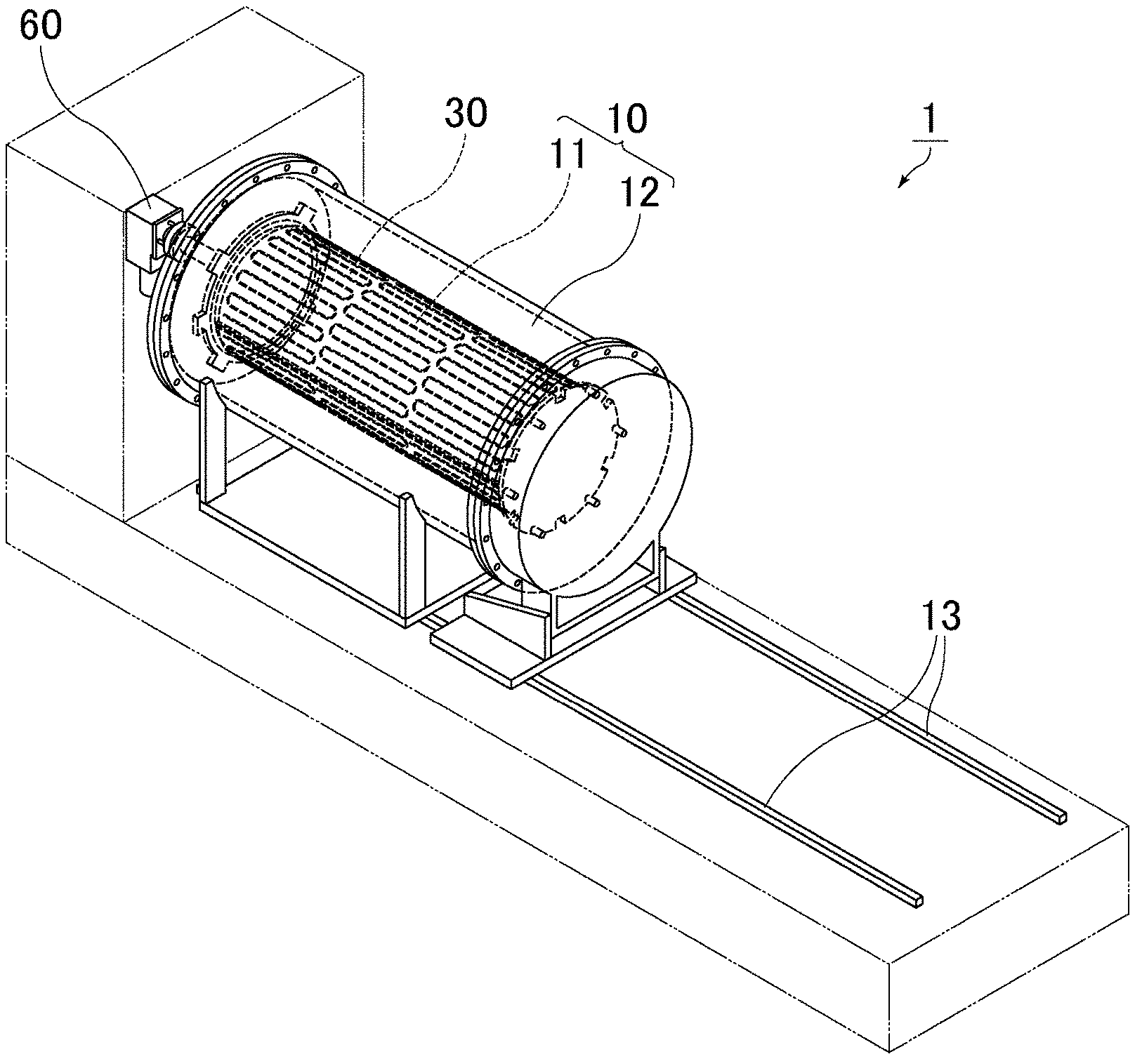
[0026] FIG. 1 is a schematic perspective view of a film-forming device according to an embodiment of the present invention. FIG. 2 is a schematic perspective view of a state in which a chamber is open in the film-forming device shown in FIG. 1.
[0027] A film-forming device 1 shown in FIG. 1 and FIG. 2 includes a chamber 10 capable of maintaining a vacuum therein, a workpiece holder 20 that aligns and holds workpieces W in multiple stages in the chamber 10, and a heater 30 that heats the inside of the chamber 10. The film-forming device 1 further includes a gas supply pipe group 40 that supplies various gases into the chamber 10, an exhaust pipe 50 that exhausts gas from the chamber 10, and a rotation mechanism 60 to rotate the workpiece holder 20.
[0028] In the film-forming device of the present invention, the chamber has its central axis aligned horizontally and preferably is a cylindrical body. In FIG. 1, the chamber 10 includes an inner chamber 11 in which the workpiece holder 20 (see FIG. 2) is placed and an outer chamber 12 that houses the inner chamber 11.
[0029] In FIG. 2, the inner chamber 11 includes a first lid 11a defining one side of the cylindrical body, a second lid 11b defining the other side of the cylindrical body, and a chamber body 11c defining a peripheral surface of the cylindrical body. The first lid 11a is fixed to the film-forming device 1, and the second lid 11b is removably connected to a flange of the chamber body 11c. The chamber body 11c is removably connected to the first lid 11a, and is movable horizontally along with the second lid 11b (see FIG. 2).
[0030] Similarly, the outer chamber 12 includes a first lid 12a defining one side of the cylindrical body, a second lid 12b defining the other side of the cylindrical body, and a chamber body 12c defining the peripheral surface of the cylindrical body. The first lid 12a is fixed to the film-forming device 1, and the second lid 12b is removably connected to a flange of the chamber body 12c. The chamber body 12c is removably connected to the first lid 12a, and is movable horizontally along with the second lid 12b (see FIG. 2).
[0031] The film-forming device 1 includes a guide 13. The second lid 11b and the chamber body 11c of the inner chamber 11 are movable horizontally on the guide 13 along with the second lid 12b and the chamber body 12c of the outer chamber 12 by the driving of a motor (not shown). The driving is stopped after these members are moved to predetermined positions, whereby the chamber 10 is opened.
[0032] As described above, when the chamber is a horizontal type and is movable horizontally, it provides enough space so that the workpieces can be easily placed and removed. Even when the number of workpieces is large, the size of the film-forming device can be reduced in the height direction. Thus, environments in which the film-forming device can be placed are less limited.
[0033] The phrase that "the chamber is movable horizontally" includes not only a case where the chamber is entirely movable horizontally but also a case where a portion of the chamber is fixed to the film-forming device. Thus, in FIG. 2, both the inner chamber and the outer chamber are considered to be movable horizontally.
[0034] In addition, the chamber including the inner chamber and the outer chamber can reduce or prevent leakage of harmful gases such as a deposition gas containing a deposition material or a modifier. As a result, a deposition gas atmosphere in the chamber is stabilized.
[0035] Although not shown in FIG. 1 and FIG. 2, preferably, the film-forming device of the present invention further includes a control mechanism that performs control such that the pressure in the outer chamber is higher than the pressure in the inner chamber.
[0036] When the pressure in the outer chamber is higher than the pressure in the inner chamber, the gas is less likely to flow from the inner chamber to the outer chamber, which provides safety during deposition, and reduces or prevents attachment of the deposition material or the like to an inner surface of the outer chamber.
[0037] The pressure in the outer chamber can be made higher than the pressure in the inner chamber by, for example, controlling the emission and gas supply in the outer chamber and the inner chamber separately while the chamber is closed.
[0038] In the film-forming device of the present invention, preferably, the workpiece holder is removably placed in the inner chamber. In FIG. 2, the workpiece holder 20 is removably connected to the first lid 11a of the inner chamber 11. The workpiece holder 20 is not connected to the second lid 11b of the inner chamber 11, and is thus cantilever-supported by the first lid 11a. The workpiece holder may be directly placed in the chamber or may be placed via a support jig fixed in the chamber.
[0039] The direction in which the workpiece holder holds the workpieces is not limited. Yet, as shown in FIG. 2, preferably, the workpiece holder aligns and holds workpieces in multiple stages such that main surfaces of the workpieces are oriented vertically relative to the central axis of the chamber. In this case, these workpieces are arranged so as to be spaced apart from each other, with their main surfaces opposing each other.
[0040] When deposition is performed on workpieces arranged with their main surfaces oriented vertically, particles as impurities are less likely to remain on the main surfaces of the workpieces. In addition, there is no risk of the workpieces falling from an upper portion of the chamber as compared to the case where the workpieces are stacked vertically. Thus, work can be performed safely.
[0041] FIG. 3 is a schematic perspective view of an example of a workpiece holder holding workpieces.
[0042] The workpiece holder 20 shown in FIG. 3 includes a pair of support plates 20a and 20b and multiple support posts 20c.sub.1, 20c.sub.2, 20c.sub.3, and 20c.sub.4 coupled to the support plates 20a and 20b. The support posts 20c.sub.1, 20c.sub.2, 20c.sub.3, and 20c.sub.4 each include multiple grooves 25 to hold the workpieces W. The workpieces W are held with their main surfaces oriented vertically. The support post 20c.sub.1 is removable.
[0043] In the film-forming device of the present invention, the position of a heater is not limited as long as the heater can heat the inside of the chamber. Yet, preferably, the heater is attached to an outer wall of the inner chamber. In particular, preferably, the heater is removably attached to the outer wall of the inner chamber.
[0044] The temperature in the inner chamber is stabilized by the heater attached to the outer wall of the inner chamber, which enables uniform deposition. In particular, when the heater is removable, it makes maintenance easy.
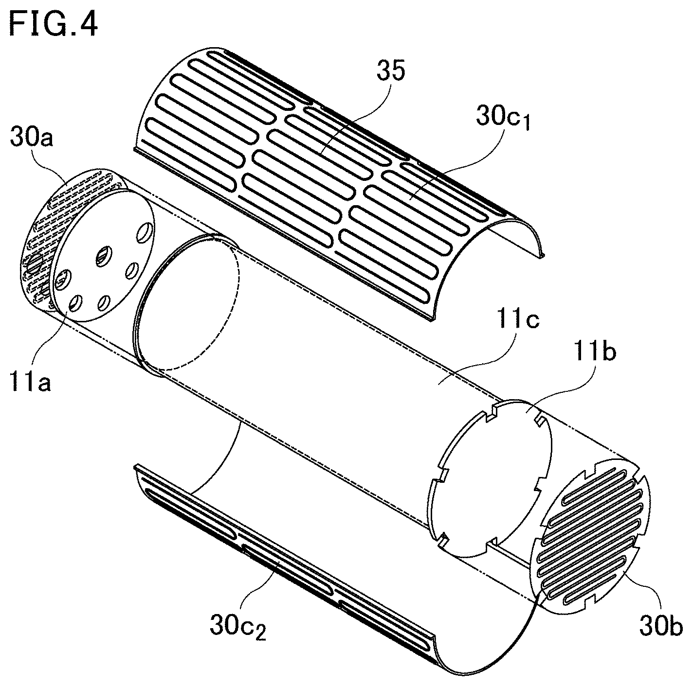
[0045] FIG. 4 is a schematic perspective view of an example of the heater to be attached to the outer wall of the inner chamber.
[0046] In FIG. 4, a heater 30a is attached to cover the outer wall of the first lid 11a of the inner chamber; a heater 30b is attached to cover the outer wall of the second lid 11b of the inner chamber; and heaters 30c.sub.1 and 30c.sub.2 are attached to cover the outer wall of the chamber body 11c of the inner chamber. The heaters 30c.sub.1 and 30c.sub.2 each include heater wires 35 in three separate blocks, i.e., the center and ends thereof when viewed in the longitudinal direction of the chamber body 11c. These blocks are separately controllable.
[0047] Preferably, the film-forming device of the present invention further includes a gas supply mechanism that supplies various gases to the inner chamber. In particular, preferably, the film-forming device further includes gas supply pipes that supply various gases to the inner chamber, such as the gas supply pipe group 40 shown in FIG. 2. Each gas supply pipe usually includes multiple gas outlets.
[0048] In FIG. 2, the gas supply pipe group 40 is connected to the first lid 11a of the inner chamber 11. The gas supply pipe group 40 is not connected to the second lid 11b of the inner chamber 11, and is thus cantilever-supported by the first lid 11a.
[0049] Examples of the gas supply pipes include the following three types: a deposition material supply pipe, a modifier supply pipe, and a carrier gas supply pipe.
[0050] There are no limitations as to how many of which types of gas supply pipes are included in the gas supply pipe group 40 shown in FIG. 2. Yet, preferably, the number of the carrier gas supply pipes is the largest.
[0051] In deposition by ALD, the deposition material supply pipe is a gas supply pipe that supplies a gas containing a deposition material that is a precursor of a compound to be deposited.
[0052] ALD can deposit metal oxides such as alumina (Al.sub.2O.sub.3) and silica (SiO.sub.2); metal nitrides such as titanium nitride (TiN); and metals such as platinum (Pt).
[0053] Examples of the deposition material include trimethylaluminum (TMA: Al(CH.sub.3).sub.3) to deposit alumina, trisdimethylaminosilane (SiH[N(CH.sub.3).sub.2].sub.3) to deposit silica, titanium tetrachloride (TiCl.sub.4) to deposit titanium nitride, and (trimethyl)methylcyclopentadienyl platinum (MeCpPtMe.sub.3) to deposit platinum.
[0054] Preferably, a carrier gas is also supplied with the deposition material through the deposition material supply pipe.
[0055] In this case, preferably, a mixed gas of the deposition material and a carrier gas is prepared outside the film-forming device, and the mixed gas is supplied into the chamber through the deposition material supply pipe.
[0056] In deposition by ALD, the modifier supply pipe is a gas supply pipe that supplies a gas as a modifier that modifies a precursor of a compound to be deposited in order to obtain a compound to be deposited.
[0057] Examples of the gas as a modifier include ozone, oxygen, water (steam), and ammonia.
[0058] In the case of alumina deposition, alumina can be deposited on workpieces by using TMA as a precursor and using ozone gas or water as a modifier.
[0059] In the case of silica deposition, silica can be deposited on workpieces by using trisdimethylaminosilane as a precursor and using ozone gas as a modifier.
[0060] In the case of titanium nitride deposition, titanium nitride can be deposited on workpieces by using titanium tetrachloride as a precursor and using ammonia gas as a modifier.
[0061] In the case of platinum deposition, platinum can be deposited on workpieces by using MeCpPtMe.sub.3 as a precursor and using oxygen gas as a modifier.
[0062] Preferably, a carrier gas is also supplied with the modifier through the modifier supply pipe.
[0063] In this case, preferably, a mixed gas of the modifier and a carrier gas is prepared outside the film-forming device, and the mixed gas is supplied into the chamber through the modifier supply pipe.
[0064] In deposition by ALD, the carrier gas supply pipe is a gas supply pipe that supplies a carrier gas as a purge gas after a deposition material is accumulated on the workpieces, and as a purge gas after a compound to be deposited is accumulated on the workpieces by a reaction of a modifier with the deposition material.
[0065] Examples of the carrier gas include inert gases such as nitrogen gas and argon gas.
[0066] Preferably, the same type of carrier gas as the carrier gas supplied through the carrier gas supply pipe is introduced into the deposition material supply pipe and the modifier supply pipe. Preferably, the carrier gas is constantly introduced through the three types of gas supply pipes.
[0067] Clogging of the gas supply pipes by the deposition material or the modifier can be prevented by constantly introducing the carrier gas through the three types of gas supply pipes.
[0068] Preferably, the film-forming device of the present invention further includes an exhaust mechanism that exhausts gas from the inner chamber and gas from the outer chamber separately. In particular, preferably, the film-forming device further includes an exhaust pipe that exhausts gas in the inner chamber, such as the exhaust pipe 50 shown in FIG. 2. Usually, the exhaust pipe includes multiple air inlets, and is connected to an exhaust device such as a vacuum pump at an end (located outside of the chamber) of the pipe so that gases in the inner chamber can be exhausted.
[0069] In FIG. 2, the exhaust pipe 50 is connected to the first lid 11a of the inner chamber 11. The exhaust pipe 50 is not connected to the second lid 11b of the inner chamber 11, and is thus cantilever-supported by the first lid 11a.
[0070] Preferably, gases supplied into the chamber through the gas supply pipes are retained on the workpieces and then flow into the exhaust pipe. Thus, although not shown in FIG. 1 and FIG. 2, preferably, the film-forming device of the present invention further includes a flow direction regulator that changes the direction of gas flow from the gas supply pipes such that the gas flow is directed to the exhaust pipes.
[0071] Preferably, the film-forming device of the present invention further includes a rotation mechanism to rotate the workpiece holder, such as the rotation mechanism 60 shown in FIG. 2. When the workpiece holder aligns and holds the workpieces in multiple stages such that the main surfaces of the workpieces are oriented vertically, the rotation mechanism includes a horizontal rotation axis. For example, a motor or the like can be used to rotate the workpiece holder.
[0072] Rotating the workpiece holder in the chamber allows the gases in the chamber to flow uniformly, so that films deposited on the main surfaces of the workpieces W can have a uniform thickness.
[0073] In FIG. 2, the rotation mechanism 60 is provided on the first lid 11a of the inner chamber 11, and is capable of rotating the workpiece holder 20 cantilever-supported by the first lid 11a.
[0074] In the film-forming device of the present invention, preferably, the chamber is further pivotable horizontally.
[0075] When the chamber is pivotable horizontally, the direction of the chamber can be changed to a position suitable for work, which makes maintenance easy.
[0076] FIG. 5 is a perspective view of a state in which the inner chamber is moved horizontally in the film-forming device shown in FIG. 1.
[0077] In FIG. 5, the second lid 11b and the chamber body 11c of the inner chamber are moved horizontally along with the second lid 12b of the outer chamber. In contrast, the first lid 11a (not shown) of the inner chamber and the first lid 12a and the chamber body 12c of the outer chamber are fixed. In this case, only the inner chamber is considered to be moved horizontally.
[0078] FIG. 6 is a perspective view of a state in which the inner chamber is pivoted horizontally in the film-forming device shown in FIG. 1.
[0079] In FIG. 6, the second lid 11b and the chamber body 11c in the inner chamber are pivoted horizontally along with the second lid 12b of the outer chamber. In this case, only the inner chamber is considered to be pivoted horizontally.
[0080] In the film-forming device of the present invention, when the chamber is pivotable horizontally, the pivot angle is not limited, but is preferably 70 degrees to 110 degrees in order to make maintenance easy.
[0081] The following describes how to use the film-forming device of the present invention, separately for deposition and for maintenance.
[0082] Before describing deposition using the film-forming device of the present invention, a deposition method by ALD is described.
[0083] According to the deposition method by ALD, workpieces are set in a chamber capable of maintaining a vacuum, and the vacuum is maintained in the chamber. In this state, the method includes supplying a deposition material into the chamber and supplying a modifier into the chamber. The method repeats these steps several times to form a reaction film on each workpiece.
[0084] The following shows an example of a deposition process using the film-forming device of the present invention.
[0085] 1. The chamber is moved horizontally by the motor and the guide and opened.
[0086] 2. The workpiece holder in which workpieces are set in advance is placed in a position on the film-forming device so as to be placed in the chamber.
[0087] 3. The chamber is moved horizontally back to the original position and closed.
[0088] 4. A vacuum is created in the chamber.
[0089] 5. The inside of the chamber is heated by the heater.
[0090] 6. When a predetermined pressure is reached in the chamber, a gas containing a deposition material and a gas containing a modifier are alternately introduced into the chamber.
[0091] 7. Gas supply is repeated until a predetermined film is formed.
[0092] 8. Heating in the chamber is stopped.
[0093] 9. The chamber is vented to atmosphere.
[0094] 10. The chamber is moved horizontally by the motor and the guide and opened.
[0095] 11. The workpiece holder is removed.
[0096] The following shows an example of a maintenance process of the film-forming device of the present invention.
[0097] 1. Only the inner chamber is moved horizontally by the motor and the guide, while the outer chamber is left unmoved.
[0098] 2. Maintenance is performed on the outer chamber and/or the inner chamber.
[0099] 3. When the inner chamber is pivotable, it makes maintenance easy. When the heater is removably attached to the outer wall of the inner chamber, it makes maintenance even easier.
[0100] The film-forming device of the present invention is not limited to the above preferred embodiments. Various modifications and changes can be made to the structure and the like of the film-forming device without departing from the gist of the present invention.
[0101] In the film-forming device of the present invention, preferably, the inner chamber and the outer chamber are separately movable horizontally. For example, the inner chamber and the outer chamber may move horizontally together, or only the inner chamber may move horizontally.
[0102] In the film-forming device of the present invention, when the chamber is horizontally pivotable, preferably, the inner chamber and the outer chamber are separately pivotable horizontally. For example, the inner chamber and the outer chamber may pivot horizontally together, or only the inner chamber may pivot horizontally.
REFERENCE SIGNS LIST
[0103] 1 film-forming device [0104] 10 chamber [0105] 11 inner chamber [0106] 11a first lid of inner chamber [0107] 11b second lid of inner chamber [0108] 11c chamber body of inner chamber [0109] 12 outer chamber [0110] 12a first lid of outer chamber [0111] 12b second lid of outer chamber [0112] 12c chamber body of outer chamber [0113] 13 guide [0114] 20 workpiece holder [0115] 20a, 20b support plate [0116] 20c.sub.1, 20c.sub.2, 20c.sub.3, 20c.sub.4 support post [0117] 25 groove [0118] 30, 30a, 30b, 30c.sub.1, 30c.sub.2 heater [0119] 35 heater wire [0120] 40 gas supply pipe group [0121] 50 exhaust pipe [0122] 60 rotation mechanism [0123] W workpiece
* * * * *
D00000
D00001
D00002
D00003
D00004
D00005
D00006
XML
uspto.report is an independent third-party trademark research tool that is not affiliated, endorsed, or sponsored by the United States Patent and Trademark Office (USPTO) or any other governmental organization. The information provided by uspto.report is based on publicly available data at the time of writing and is intended for informational purposes only.
While we strive to provide accurate and up-to-date information, we do not guarantee the accuracy, completeness, reliability, or suitability of the information displayed on this site. The use of this site is at your own risk. Any reliance you place on such information is therefore strictly at your own risk.
All official trademark data, including owner information, should be verified by visiting the official USPTO website at www.uspto.gov. This site is not intended to replace professional legal advice and should not be used as a substitute for consulting with a legal professional who is knowledgeable about trademark law.