Drive Shaft And Method For Producing Drive Shaft
Kamikawa; Mitsuru ; et al.
U.S. patent application number 16/827749 was filed with the patent office on 2020-10-01 for drive shaft and method for producing drive shaft. The applicant listed for this patent is HONDA MOTOR CO., LTD.. Invention is credited to Mitsuru Kamikawa, Masaki Kawamura, Kazuya Kumei, Takafumi Murakami, Naoto Shibata, Ko Sugai, Yutaka Takeuchi, Masafumi Yamamoto.
| Application Number | 20200307312 16/827749 |
| Document ID | / |
| Family ID | 1000004768274 |
| Filed Date | 2020-10-01 |
| United States Patent Application | 20200307312 |
| Kind Code | A1 |
| Kamikawa; Mitsuru ; et al. | October 1, 2020 |
DRIVE SHAFT AND METHOD FOR PRODUCING DRIVE SHAFT
Abstract
A drive shaft is configured by joining solid stub shafts formed of a medium carbon steel to both ends of a hollow tubular body formed of a medium carbon steel. When expressed as grain size number, the grain size of the hollow tubular body at joint parts where the hollow tubular body and the solid stub shafts are joined together ranges from #5 to #9, and the grain size of the solid stub shafts at the joint parts ranges from #10 to #12.
| Inventors: | Kamikawa; Mitsuru; (Tokyo, JP) ; Shibata; Naoto; (Tokyo, JP) ; Sugai; Ko; (Tokyo, JP) ; Yamamoto; Masafumi; (Tokyo, JP) ; Murakami; Takafumi; (Tokyo, JP) ; Kumei; Kazuya; (Tokyo, JP) ; Takeuchi; Yutaka; (Tokyo, JP) ; Kawamura; Masaki; (Tokyo, JP) | ||||||||||
| Applicant: |
|
||||||||||
|---|---|---|---|---|---|---|---|---|---|---|---|
| Family ID: | 1000004768274 | ||||||||||
| Appl. No.: | 16/827749 | ||||||||||
| Filed: | March 24, 2020 |
| Current U.S. Class: | 1/1 |
| Current CPC Class: | B60B 2310/54 20130101; B60B 35/12 20130101; B60B 2360/102 20130101; B23K 2101/04 20180801; B23K 20/129 20130101; B60B 2310/208 20130101; B60B 2310/3025 20130101 |
| International Class: | B60B 35/12 20060101 B60B035/12; B23K 20/12 20060101 B23K020/12 |
Foreign Application Data
| Date | Code | Application Number |
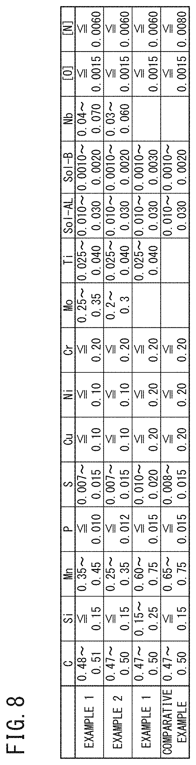
|---|---|---|
| Mar 28, 2019 | JP | 2019-064267 |
Claims
1. A drive shaft comprising: a hollow tubular body formed of a medium carbon steel; and solid stub shafts formed of a medium carbon steel and joined to both ends of the hollow tubular body, wherein, when grain size is expressed as grain size number, grain size of the hollow tubular body at joint parts where the hollow tubular body and the solid stub shafts are joined together ranges from #5 to #9, and grain size of the solid stub shafts at the joint parts ranges from #10 to #12.
2. The drive shaft according to claim 1, wherein the medium carbon steel serving as a material of the solid stub shafts contains, by weight, 0.45-0.51% C, 0.25% or less Si, 0.30-0.50% Mn, 0.015% or less P, 0.008-0.020% S, 0.2% or less Cu, 0.1% or less Ni, 0.1-0.2% Cr, at least one of 0.05-0.25% Mo, 0.03-0.08% Nb, and 0.01-0.05% Ti, 0.02-0.04% Al, and 10-30 ppm B, and a balance of Fe and unavoidable impurities, and the grain size number of the medium carbon steel ranges from #9 to #11.
3. The drive shaft according to claim 2, wherein at least one of NbC, Mo.sub.2C, and TiC precipitates in a grain boundary in metallic structure of the solid stub shafts.
4. The drive shaft according to claim 1, wherein the medium carbon steel serving as a material of the hollow tubular body contains, by weight, 0.43-0.47% C, 0.20% or less Si, 0.60-0.90% Mn, 0.010% or less P, 0.008-0.020% S, 0.1% or less Cu, 0.1% or less Ni, 0.05% or less Cr, at least one of 0.05% or less Mo, 0.01-0.03% Nb, and 0.01-0.05% Ti, and 0.02-0.04% Al, and a balance of Fe and unavoidable impurities, and the grain size number of the medium carbon steel ranges from #4 to #9.
5. The drive shaft according to claim 1, wherein part of the hollow tubular body penetrates into the solid stub shafts by a thickness of 1-30 .mu.m at the joint parts.
6. A production method for obtaining a drive shaft by joining solid stub shafts formed of a medium carbon steel to both ends of a hollow tubular body formed of a medium carbon steel, the production method comprising: obtaining the solid stub shafts by cold forging; and joining the hollow tubular body and the solid stub shafts together by friction welding, and setting, when grain size is expressed as grain size number, grain size of the hollow tubular body at joint parts where the hollow tubular body and the solid stub shafts are joined together to range from #5 to #9 and setting grain size of the solid stub shafts at the joint parts to range from #10 to #12.
7. The production method according to claim 6, wherein, during the friction welding, the solid stub shafts and the hollow tubular body rotating relative to each other are brought into contact, a thrust force is applied by a thrust force applying device to the hollow tubular body or the solid stub shafts such that the solid stub shafts are relatively pressed against the hollow tubular body to generate frictional heat to soften the hollow tubular body and the solid stub shafts, and then additional thrust force is applied to join the hollow tubular body and the solid stub shafts together by solid phase joining.
8. The production method according to claim 6, wherein the medium carbon steel used as a material for the solid stub shafts contains, by weight, 0.45-0.51% C, 0.25% or less Si, 0.30-0.50% Mn, 0.015% or less P, 0.008-0.020% S, 0.2% or less Cu, 0.1% or less Ni, 0.1-0.2% Cr, at least one of 0.05-0.25% Mo, 0.03-0.08% Nb, and 0.01-0.05% Ti, 0.02-0.04% Al, and 10-30 ppm B, and a balance of Fe and unavoidable impurities, and the grain size number of the medium carbon steel ranges from #9 to #11.
9. The production method according to claim 8, further comprising: annealing the drive shaft at a temperature of 650-720.degree. C. for 30-90 minutes after the joining by friction welding; and hardening the drive shaft after the annealing, wherein at least one of NbC, Mo.sub.2C, and TiC is precipitated in a grain boundary in metallic structure of the solid stub shafts.
10. The production method according to claim 6, wherein the medium carbon steel used as a material for the hollow tubular body contains, by weight, 0.43-0.47% C, 0.20% or less Si, 0.60-0.90% Mn, 0.010% or less P, 0.008-0.020% S, 0.1% or less Cu, 0.1% or less Ni, 0.05% or less Cr, at least one of 0.05% or less Mo, 0.01-0.03% Nb, and 0.01-0.05% Ti, and 0.02-0.04% Al, and a balance of Fe and unavoidable impurities, and the grain size number of the medium carbon steel ranges from #4 to #9.
Description
CROSS-REFERENCE TO RELATED APPLICATION
[0001] This application is based upon and claims the benefit of priority from Japanese Patent Application No. 2019-064267 filed on Mar. 28, 2019, the contents of which are incorporated herein by reference.
BACKGROUND OF THE INVENTION
Field of the Invention
[0002] The present invention relates to drive shafts for transferring driving force for traveling generated by driving force generating mechanisms to wheels in automobiles and methods for producing such drive shafts.
Description of the Related Art
[0003] Drive shafts of automobiles need to be lightweight and, at the same time, need to have excellent stiffness at ends to which, for example, constant velocity joints are attached. To meet these demands, a hollow tubular body is typically used as a shaft portion, and solid stub shafts are joined to the shaft portion (for example, see Japanese Laid-Open Patent Publication No. 2008-087003). The members may be joined together by, for example, friction welding.
SUMMARY OF THE INVENTION
[0004] While the thickness of the hollow tubular body corresponds to the difference between the outer diameter and the inner diameter, the thickness of the solid stub shafts corresponds to the diameter. As can be seen from this, the difference between the thicknesses of the hollow tubular body and the solid stub shafts is large. Joined products with such large differences in thickness often crack during hardening.
[0005] If hardening conditions are set such that hardened layers with predetermined depths are reliably formed in the solid stub shafts, grains in the hollow tubular body become coarse and cause a decrease in the strength of the hollow tubular body. To avoid this, hardening may not be performed on the hollow tubular body. In this case, however, the outer diameter or thickness of the hollow tubular body needs to be increased to sufficiently increase the strength of the hollow tubular body. Thus, in the case where the hollow tubular body and the solid stub shafts are joined together to produce a drive shaft, it is inconveniently difficult to ensure sufficient strength while reducing the weight.
[0006] A general object of the present invention is to provide a drive shaft including a hollow tubular body and a solid stub shaft joined together.
[0007] A principal object of the present invention is to provide a drive shaft that is lightweight but exhibits sufficient strength.
[0008] Another object of the present invention is to provide a drive shaft production method for obtaining the above-described drive shaft.
[0009] According to an embodiment of the present invention, a drive shaft comprises:
[0010] a hollow tubular body formed of a medium carbon steel; and
[0011] solid stub shafts formed of a medium carbon steel and joined to both ends of the hollow tubular body,
[0012] wherein, when grain size is expressed as grain size number, grain size of the hollow tubular body at joint parts where the hollow tubular body and the solid stub shafts are joined together ranges from #5 to #9, and grain size of the solid stub shafts at the joint parts ranges from #10 to #12.
[0013] Moreover, according to another embodiment of the present invention, a production method for obtaining a drive shaft by joining solid stub shafts formed of a medium carbon steel to both ends of a hollow tubular body formed of a medium carbon steel comprises:
[0014] obtaining the solid stub shafts by cold forging; and
[0015] joining the hollow tubular body and the solid stub shafts together by friction welding, and setting, when grain size is expressed as grain size number, grain size of the hollow tubular body at joint parts where the hollow tubular body and the solid stub shafts are joined together to range from #5 to #9 and setting grain size of the solid stub shafts at the joint parts to range from #10 to #12.
[0016] According to the present invention, the grain size numbers at the joint parts where the hollow tubular body and the solid stub shafts are joined together are set to range from #5 to #9 in the hollow tubular body and from #10 to #12 in the solid stub shafts, respectively. By reducing the size of the grains at the joint parts in this manner, a drive shaft with excellent joint strength can be obtained. Moreover, the drive shaft obtained in this manner also exhibits excellent torsional strength and fatigue strength.
[0017] In addition, in this case, the weight of the drive shaft can be reduced since the hollow tubular body has an empty space inside.
[0018] The above and other objects, features, and advantages of the present invention will become more apparent from the following description when taken in conjunction with the accompanying drawings in which a preferred embodiment of the present invention is shown by way of illustrative example.
BRIEF DESCRIPTION OF THE DRAWINGS
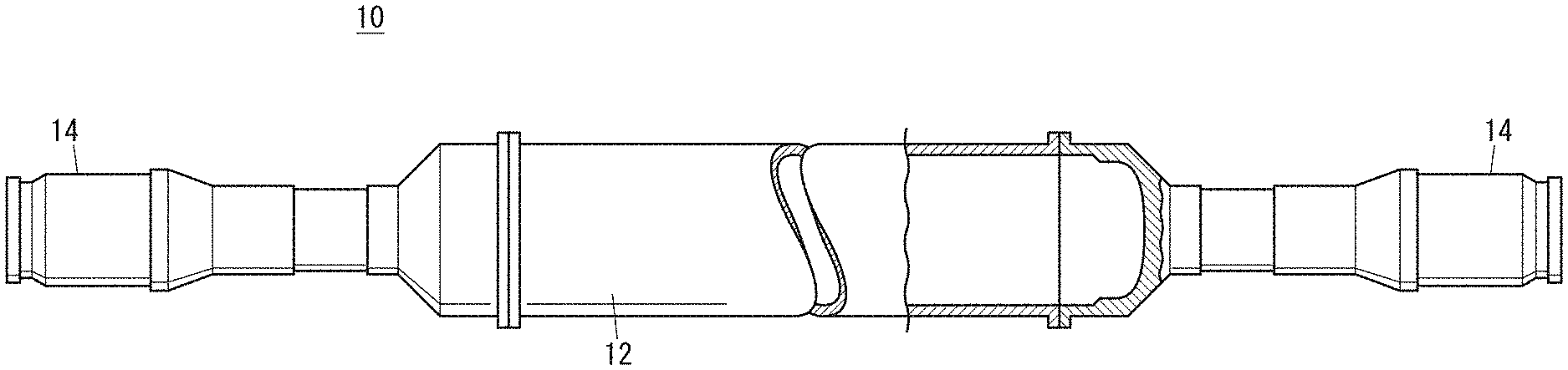
[0019] FIG. 1 is a side view, partially sectioned in a longitudinal direction, of a drive shaft according to an embodiment of the present invention;
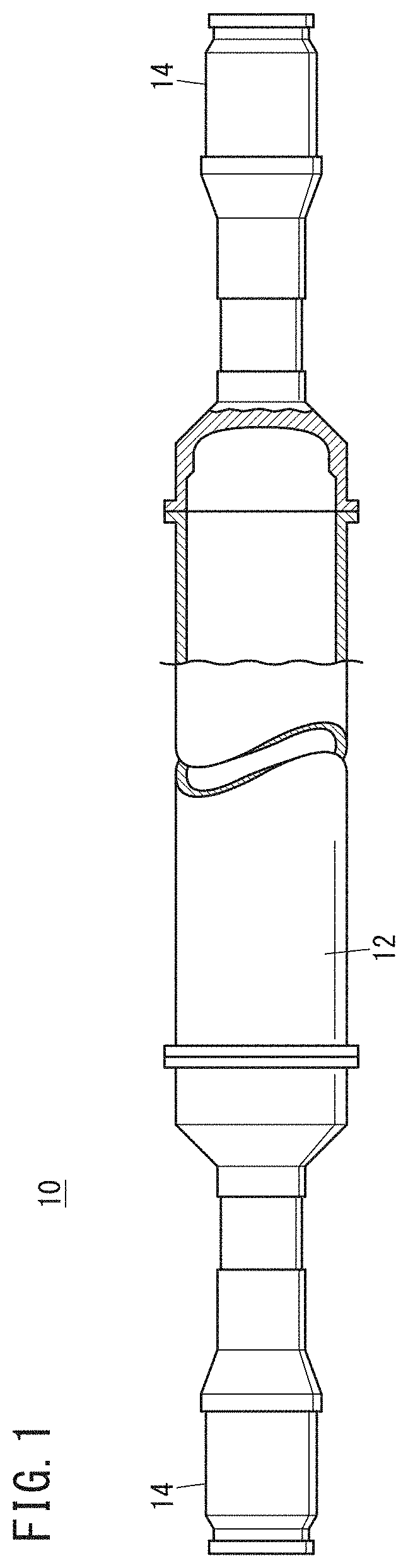
[0020] FIG. 2 is a photomicrograph showing an area adjacent to a joint part of a hollow tubular body and a solid stub shaft;
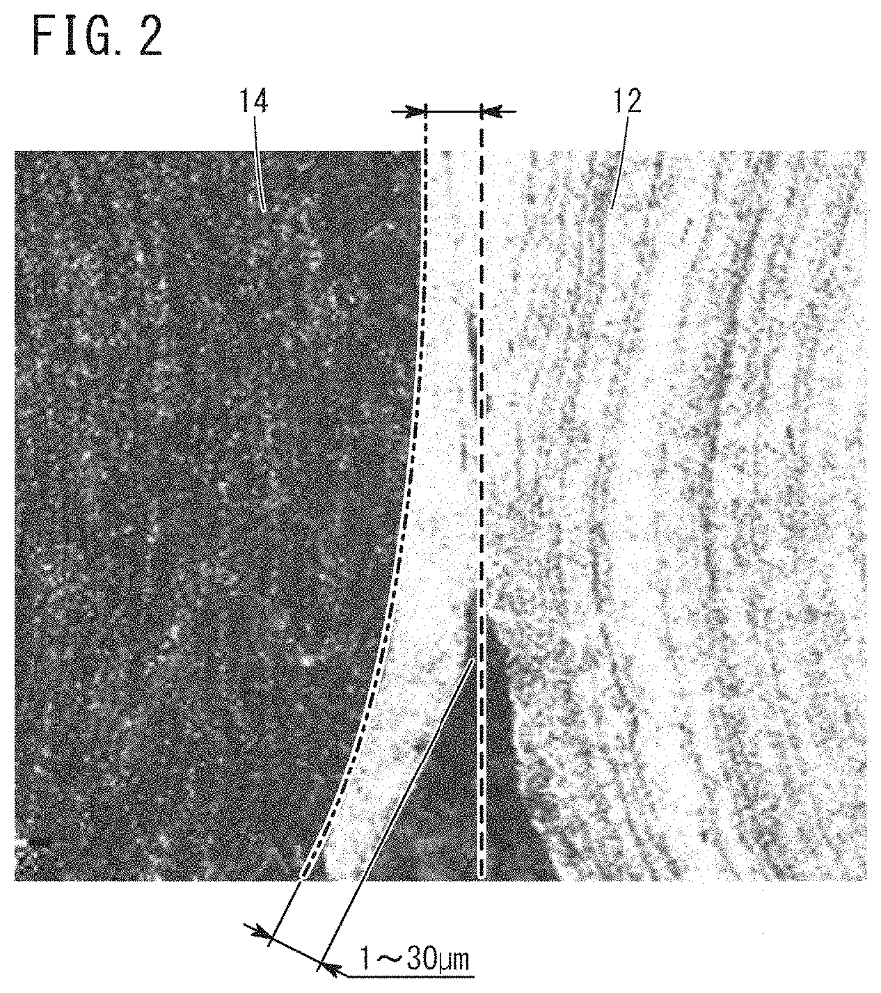
[0021] FIG. 3 is a photomicrograph showing an area adjacent to the joint part;
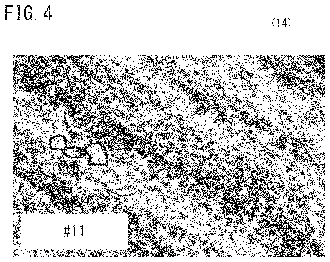
[0022] FIG. 4 is an enlarged photomicrograph of a principal part indicated by C1 in FIG. 3;
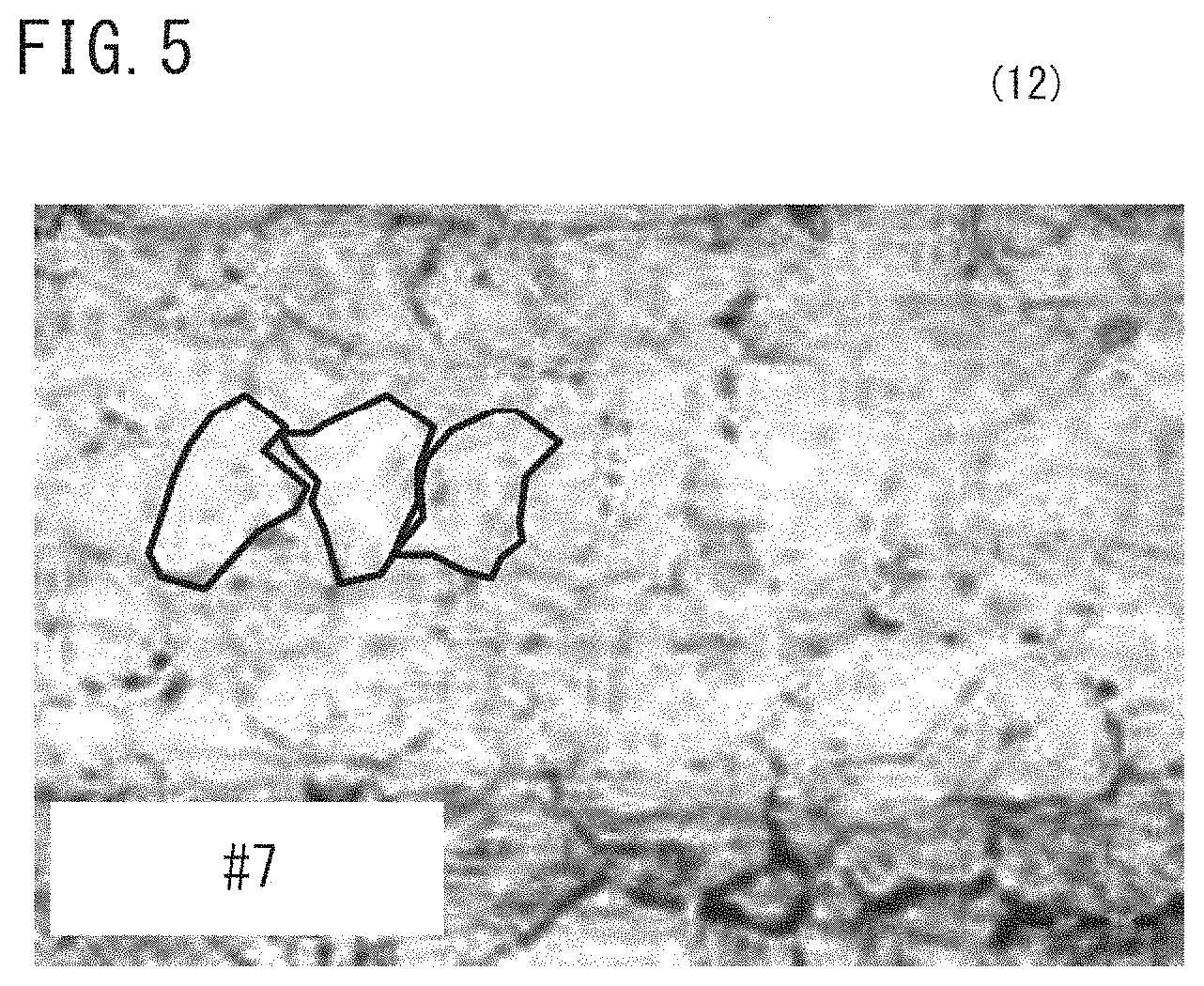
[0023] FIG. 5 is an enlarged photomicrograph of a principal part indicated by C2 in FIG. 3;
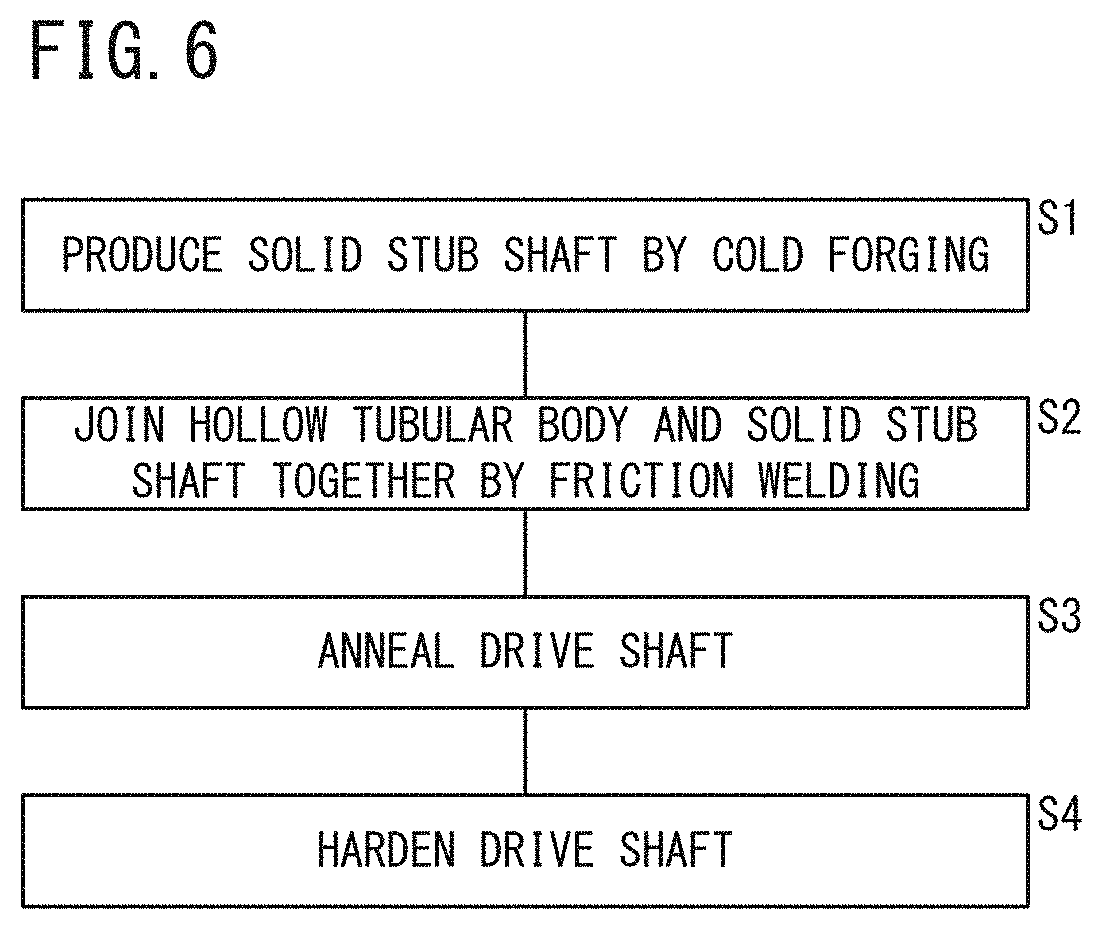
[0024] FIG. 6 is a schematic flow diagram of a method for producing a drive shaft according to an embodiment of the present invention;
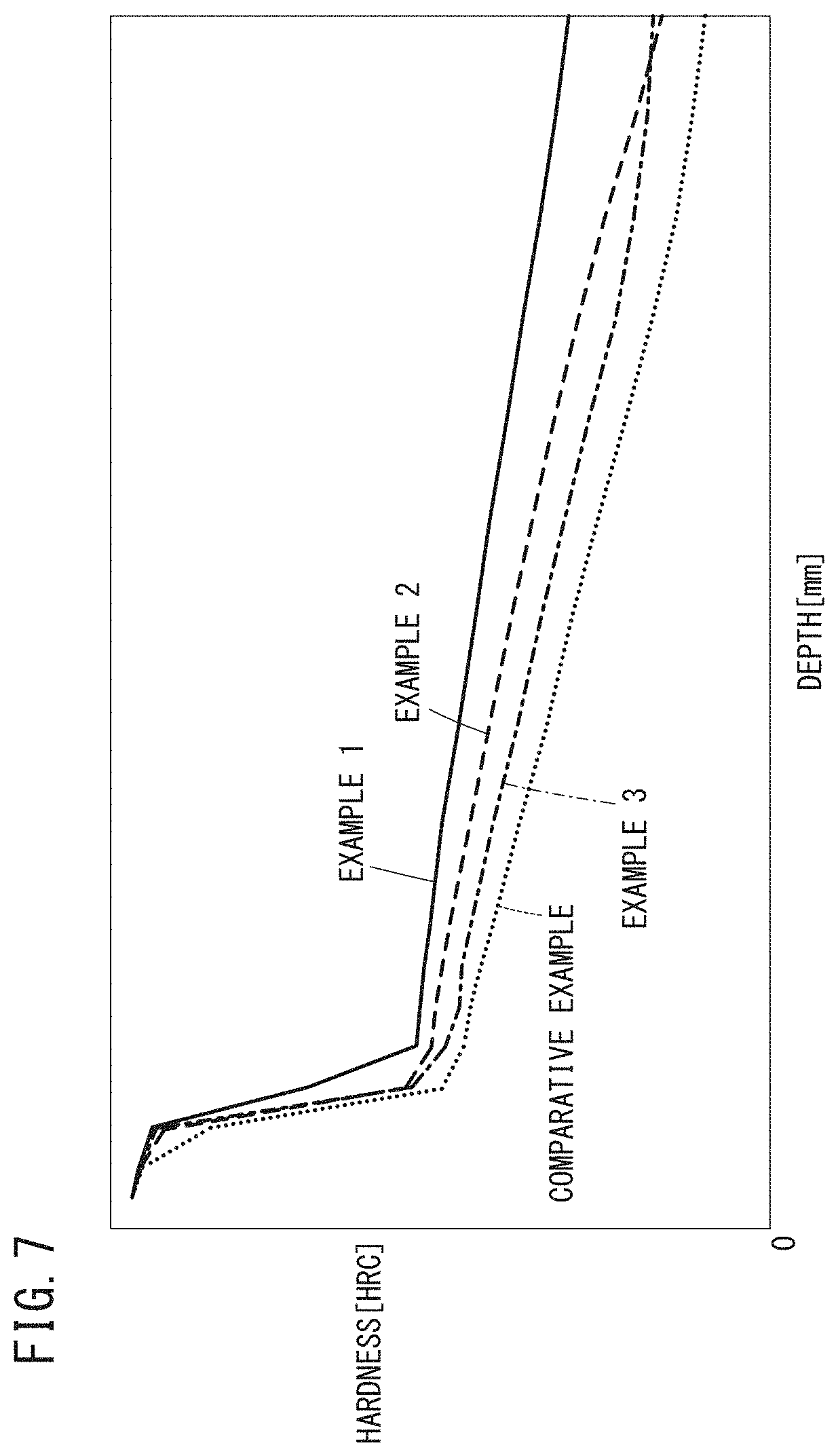
[0025] FIG. 7 is a graph showing relationships between the depth and the Rockwell hardness (C scale; HRC) of a typical medium carbon steel (comparative example) and medium carbon steels (Examples 1 to 3) with predetermined compositions after being subjected to induction hardening under identical conditions;
[0026] FIG. 8 shows the compositions of the medium carbon steels of Examples 1 to 3;
[0027] FIG. 9 is a graph showing results of static destructive testing performed on the medium carbon steel in Example 2 and the medium carbon steel in the comparative example; and
[0028] FIG. 10 is a graph showing results of fatigue testing performed on the medium carbon steel in Example 2 and the medium carbon steel in the comparative example.
DESCRIPTION OF THE PREFERRED EMBODIMENTS
[0029] A preferred embodiment of a drive shaft according to the present invention will be described in detail below with reference to the accompanying drawings, in relation to a method for producing the drive shaft.
[0030] FIG. 1 is a side view, partially sectioned in a longitudinal direction, of a drive shaft 10 according to an embodiment of the present invention. The drive shaft 10 includes a hollow tubular body 12 and solid stub shafts 14 disposed at both ends of the hollow tubular body 12.
[0031] In this embodiment, the hollow tubular body 12 is formed of a medium carbon steel. As a suitable example, the medium carbon steel contains, by weight, 0.43-0.47% carbon (C), 0.20% or less silicon (Si), 0.60-0.90% manganese (Mn), 0.010% or less phosphorus (P), 0.008-0.020% sulfur (S), 0.1% or less copper (Cu), 0.1% or less nickel (Ni), 0.05% or less chromium (Cr), at least one of 0.05% or less molybdenum (Mo), 0.01-0.03% niobium (Nb), and 0.01-0.05% titanium (Ti), and 0.02-0.04% aluminum (Al), and a balance of iron (Fe) and unavoidable impurities. Moreover, when expressed as grain size number, the grain size of the medium carbon steel ranges from #4 to #9.
[0032] The solid stub shafts 14 are also formed of a medium carbon steel. As a suitable example, the medium carbon steel contains, by weight, 0.45-0.51% C, 0.25% or less Si, 0.30-0.50% Mn, 0.015% or less P, 0.008-0.020% S, 0.2% or less Cu, 0.1% or less Ni, 0.1-0.2% Cr, at least one of 0.05-0.25% Mo, 0.03-0.08% Nb, and 0.01-0.05% Ti, 0.02-0.04% Al, and 10-30 ppm boron (B), and a balance of Fe and unavoidable impurities.
[0033] That is, the medium carbon steel serving as the material of the solid stub shafts 14 contains more Mo, Nb, and/or Ti compared with the medium carbon steel serving as the material of the hollow tubular body 12. Moreover, when expressed as grain size number, the grain size of the medium carbon steel making up the solid stub shafts 14 ranges from #9 to #11.
[0034] FIG. 2 is a photomicrograph showing an area adjacent to a joint part of the hollow tubular body 12 and one of the solid stub shafts 14. The broken line in FIG. 2 indicates the joint interface. The hollow tubular body 12 and the solid stub shafts 14 are joined together by friction welding (described below). As is clear from FIG. 2, part of the hollow tubular body 12 deformed to penetrate into (become entangled in) the solid stub shaft 14.
[0035] The thickness of the penetrating part (amount of penetration) of the hollow tubular body 12 is preferably 1-30 .mu.m. If the amount of penetration is less than 1 .mu.m, the joint strength may be insufficient. On the other hand, if the amount of penetration is more than 30 .mu.m, the hollow tubular body 12 may crack and break. A preferred amount of penetration of the hollow tubular body 12 is about 15 .mu.m.
[0036] FIG. 3 is another photomicrograph showing an area adjacent to the joint part. Furthermore, FIGS. 4 and 5 are enlarged photomicrographs of principal parts respectively indicated by C1 and C2 in FIG. 3. The contour lines in FIGS. 4 and 5 indicate grain boundaries. When expressed as grain size number, the grain sizes of the hollow tubular body 12 and the solid stub shafts 14 determined on a basis of the magnification of the photomicrographs and the dimensions of the contour lines ranged from #5 to #9 and from #10 to #12, respectively. It is clear from the results that the grains of both the solid stub shafts 14 and the hollow tubular body 12 became finer in the area adjacent to the joint part.
[0037] As a result of an analysis of areas adjacent to the grain boundaries, the presence of Mo.sub.2C, NbC, and TiC serving as precipitated particles was found. From this, it can be surmised that Mo.sub.2C, NbC, and TiC prevented grain growth. Moreover, Mo.sub.2C, NbC, and TiC prevent formation of Fe.sub.3C, which is a brittle substance, and thereby improve the strength of grain boundaries. Thus, when the drive shaft 10 is subjected to tensile testing, it is not the joint part but the hollow tubular body 12 that breaks.
[0038] Next, a method for producing the drive shaft 10 according to an embodiment will be described on a basis of a schematic flow diagram illustrated in FIG. 6. The production method includes a stub production step S1 of obtaining the solid stub shafts 14, a joint step S2 of joining the hollow tubular body 12 and the solid stub shafts 14 together, an annealing step S3, and a hardening step S4.
[0039] As described above, the medium carbon steel containing, by weight, 0.45-0.51% C, 0.25% or less Si, 0.30-0.50% Mn, 0.015% or less P, 0.008-0.020% S, 0.2% or less Cu, 0.1% or less Ni, 0.1-0.2% Cr, at least one of 0.05-0.25% Mo, 0.03-0.08% Nb, and 0.01-0.05% Ti, 0.02-0.04% Al, and 10-30 ppm B, and a balance of Fe and unavoidable impurities, is preferred as a material for obtaining the solid stub shafts 14. When expressed as grain size number, the grain size of the medium carbon steel ranges from #9 to #11.
[0040] The steel material composed of the medium carbon steel with the above-described composition is rolled at a temperature of 850.degree. C. or less. Due to the rolling in the temperature range, strain remains in the steel material. In addition, transformation from austenite to ferrite occurs, and ferrite precipitates from uneven parts in which the strain remains. This results in a soft structure that includes fine grains and that can be easily shaped.
[0041] Subsequently, the steel material is spheroidized. To do this, for example, the steel material may be kept at 720-760.degree. C. for a predetermined period of time and then cooled slowly at a cooling speed of 0.5.degree. C./min down to 600.degree. C. This promotes spheroidization of cementite (Fe.sub.3C), and thus the steel material obtains a structure containing a significant amount of relatively soft ferrite.
[0042] Next, the spheroidized steel material is cold-forged in the stub production step S1. In cold forging, grains can be prevented from becoming coarser. In other words, the grains are kept fine before and after cold forging. In addition, the solid stub shafts 14 can be easily shaped even by cold forging since the steel material is soft.
[0043] Next, the joint step S2 is performed. In this step, friction welding is performed so that members are pressure-welded to each other. To do so, either the solid stub shaft 14 or the hollow tubular body 12 is rotated while being held by a holder, and a thrust force is applied to a holder holding the other. Conditions such as the rotational speed and the thrust force are set such that the surface temperature during joining reaches 800-870.degree. C.
[0044] As described above, the medium carbon steel containing, by weight, 0.43-0.47% C, 0.20% or less Si, 0.60-0.90% Mn, 0.010% P, 0.008-0.020% S, 0.1% or less Cu, 0.1% or less Ni, 0.05% or less Cr, at least one of 0.05% or less Mo, 0.01-0.03% Nb, 0.01-0.05% Ti, and 0.02-0.04% Al, and a balance of Fe and unavoidable impurities, is preferred as a material for the hollow tubular body 12. When expressed as grain size number, the grain size of the medium carbon steel ranges from #4 to #9.
[0045] When the solid stub shafts 14 containing Mo, Nb, and/or Ti as described above is joined to the hollow tubular body 12 formed of the above-described medium carbon steel by friction welding, at least one of Mo.sub.2C, NbC, and TiC precipitates in the grain boundaries. This prevents formation of Fe.sub.3C, resulting in an improvement in the strength of the grain boundaries.
[0046] Next, the annealing step S3 is performed. That is, the drive shaft 10 is heated to a predetermined temperature. The annealing removes the strain that has occurred during friction welding and promotes recrystallization. The recrystallized grains become as fine as about 20 .mu.m. Moreover, NbC, VC, Mo.sub.2C, or the like also precipitate in the grain boundaries by annealing. Due to the finer grains and the precipitation of carbides in the grain boundaries, the joint parts attain an excellent strength. It is preferable that the annealing temperature be in the range of 650 to 720.degree. C. and maintained for 30 to 90 minutes.
[0047] Next, the hardening step S4 is performed after predetermined machine work for shaping is performed on the drive shaft 10. In this step, induction hardening is preferably performed as it has various advantages such as excellent thermal efficiency.
[0048] In this embodiment, the overall drive shaft 10 can be hardened. Here, hardening progresses easily in the solid stub shafts 14 formed of the medium carbon steel with the above-described composition compared with other medium carbon steels. This will be explained with a specific example below. FIG. 7 shows measurement results of Rockwell hardness (C scale; HRC) of a typical medium carbon steel (comparative example) and medium carbon steels (Examples 1 to 3) with the above-described compositions after being subjected to induction hardening under identical conditions. The abscissa represents the depth, and the ordinate represents the HRC. Moreover, the specific compositions of Examples 1 to 3 are shown in FIG. 8. Here, "Sol-" in FIG. 8 indicates that the element is a solid solution.
[0049] As illustrated in FIG. 7, all the medium carbon steels of Examples 1 to 3 exhibit higher hardness than the medium carbon steel according to a known technology serving as the comparative example. It is apparent from the above that hardening progressed more easily in Examples 1 to 3 than in the known technology and that hardened layers were sufficiently formed.
[0050] Thus, in this embodiment, hardened layers with predetermined depths can be reliably formed in the solid stub shafts 14 even when hardening is performed under conditions where hardened layers with sufficient depths are formed in the hollow tubular body 12. This is because the medium carbon steel serving as the material of the solid stub shafts 14 has excellent hardenability as described above. That is, grains in the structure of the hollow tubular body 12 subjected to hardening are prevented from becoming coarse. Consequently, by hardening, the strength of the hollow tubular body 12 can be improved while the grains are prevented from becoming coarse.
[0051] Thus, the strength of the hollow tubular body 12 does not need to be increased by increasing the outer diameter or thickness of the hollow tubular body 12 instead of performing hardening. The weight of the drive shaft 10 can be reduced accordingly. Moreover, since the hollow tubular body 12 is not exposed to excessive heating, quenching cracks in the drive shaft 10 can be prevented.
[0052] In addition, the drive shaft 10 includes fine grains in the joint parts and carbides precipitating in the grain boundaries. The carbides produce a so-called particle dispersion strengthening effect. For the above-described reasons, the joint parts have excellent strength and toughness.
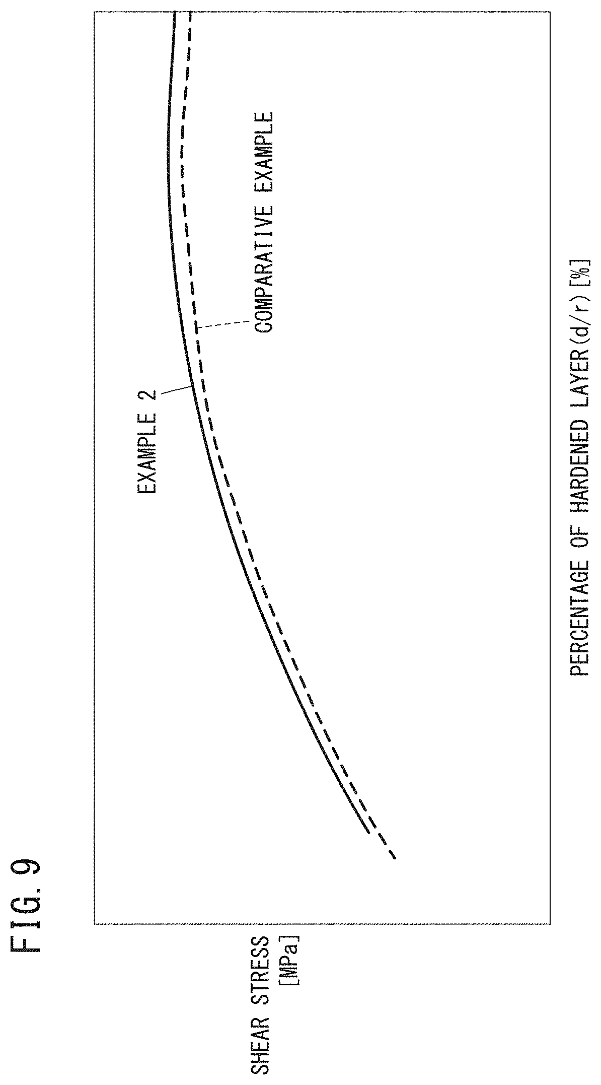
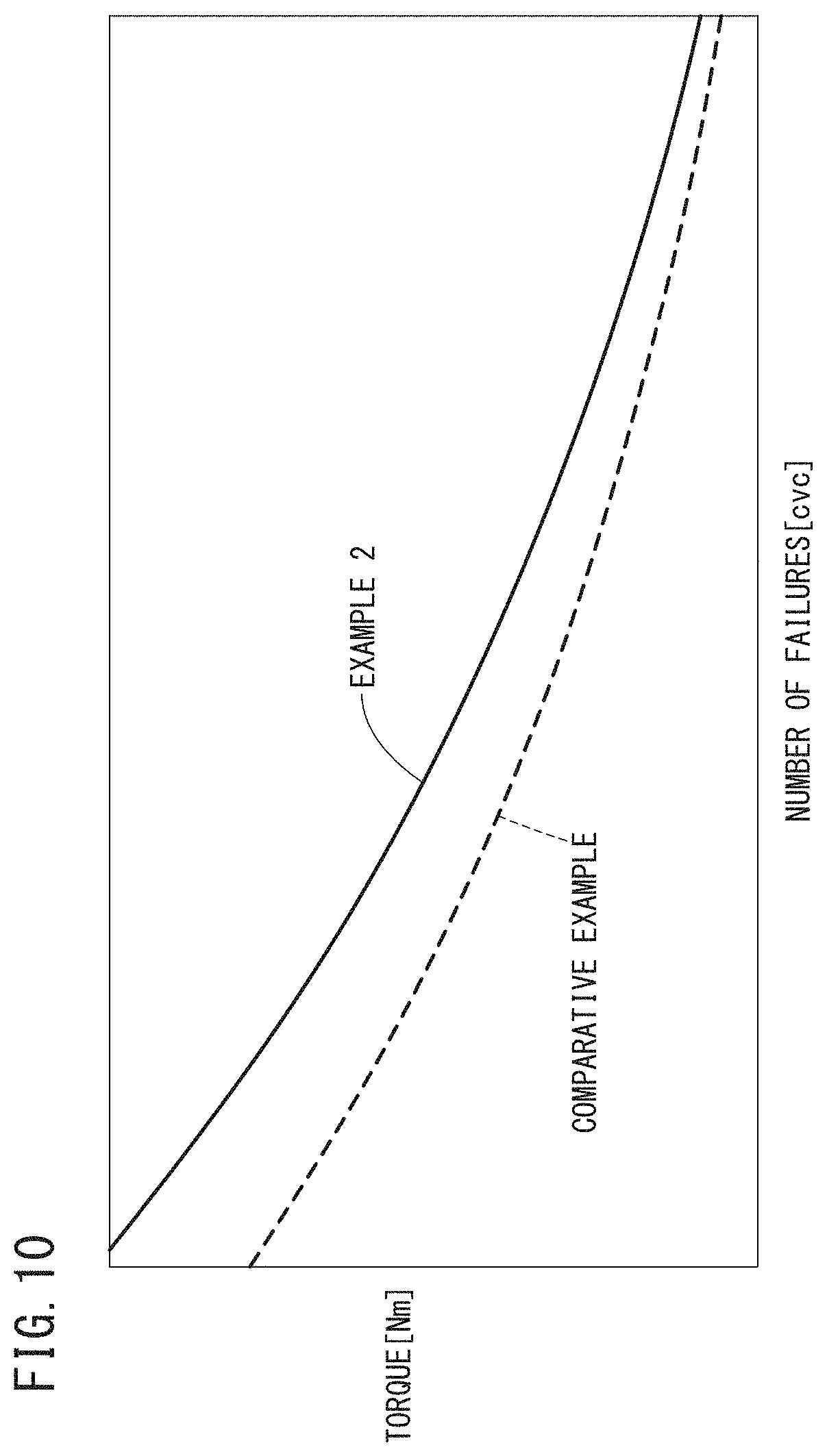
[0053] Furthermore, results of static destructive testing performed on the medium carbon steel in Example 2 and the medium carbon steel in the comparative example are shown in FIG. 9. In addition, FIG. 10 shows results of fatigue testing performed on the medium carbon steel in Example 2 and the medium carbon steel in the comparative example. As is clear from FIGS. 9 and 10, the medium carbon steel in Example 2 exhibits excellent shear stress and fatigue strength compared with the medium carbon steel of the known technology. That is, the solid stub shafts 14 exhibit excellent shear stress and fatigue strength.
[0054] Thus, when the drive shaft 10 is subjected to tensile testing, it is not the joint parts but the hollow tubular body 12 that breaks.
[0055] Moreover, since the hollow tubular body 12 is lightweight, the weight of the drive shaft 10 can be reduced. That is, in this embodiment, although the hollow tubular body 12 and the solid stub shafts 14 are joined together, the drive shaft 10 has a sufficient strength while the weight is reduced.
[0056] The present invention is not limited in particular to the embodiments described above, and various modifications can be made thereto without departing from the scope of the present invention.
* * * * *
D00000
D00001
D00002
D00003
D00004
D00005
D00006
D00007
D00008
D00009
D00010
XML
uspto.report is an independent third-party trademark research tool that is not affiliated, endorsed, or sponsored by the United States Patent and Trademark Office (USPTO) or any other governmental organization. The information provided by uspto.report is based on publicly available data at the time of writing and is intended for informational purposes only.
While we strive to provide accurate and up-to-date information, we do not guarantee the accuracy, completeness, reliability, or suitability of the information displayed on this site. The use of this site is at your own risk. Any reliance you place on such information is therefore strictly at your own risk.
All official trademark data, including owner information, should be verified by visiting the official USPTO website at www.uspto.gov. This site is not intended to replace professional legal advice and should not be used as a substitute for consulting with a legal professional who is knowledgeable about trademark law.