Methods And Systems For Improving Transducer Dynamics
Lindemann; Eric ; et al.
U.S. patent application number 16/816790 was filed with the patent office on 2020-10-01 for methods and systems for improving transducer dynamics. This patent application is currently assigned to Cirrus Logic International Semiconductor Ltd.. The applicant listed for this patent is Cirrus Logic International Semiconductor Ltd.. Invention is credited to Eric Lindemann, Emmanuel Marchais, John L. Melanson, Carl Lennart Stahl.
| Application Number | 20200306796 16/816790 |
| Document ID | / |
| Family ID | 1000004763856 |
| Filed Date | 2020-10-01 |


View All Diagrams
| United States Patent Application | 20200306796 |
| Kind Code | A1 |
| Lindemann; Eric ; et al. | October 1, 2020 |
METHODS AND SYSTEMS FOR IMPROVING TRANSDUCER DYNAMICS
Abstract
A system may include a signal generator configured to generate a raw waveform signal and a modeling subsystem configured to implement a discrete time model of an electromagnetic load that emulates a virtual electromagnetic load and further configured to modify the raw waveform signal to generate a waveform signal for driving the electromagnetic load by modifying the virtual electromagnetic load to have a desired characteristic, applying the discrete time model to the raw waveform signal to generate the waveform signal for driving the electromagnetic load, and applying the waveform signal to the electromagnetic load.
| Inventors: | Lindemann; Eric; (Boulder, CO) ; Stahl; Carl Lennart; (Malmo, SE) ; Marchais; Emmanuel; (Dripping Springs, TX) ; Melanson; John L.; (Austin, TX) | ||||||||||
| Applicant: |
|
||||||||||
|---|---|---|---|---|---|---|---|---|---|---|---|
| Assignee: | Cirrus Logic International
Semiconductor Ltd. Edinburgh GB |
||||||||||
| Family ID: | 1000004763856 | ||||||||||
| Appl. No.: | 16/816790 | ||||||||||
| Filed: | March 12, 2020 |
Related U.S. Patent Documents
| Application Number | Filing Date | Patent Number | ||
|---|---|---|---|---|
| 62826348 | Mar 29, 2019 | |||
| 62826388 | Mar 29, 2019 | |||
| Current U.S. Class: | 1/1 |
| Current CPC Class: | B06B 1/0215 20130101; B06B 1/045 20130101; B06B 1/0261 20130101; G08B 6/00 20130101; G06F 1/022 20130101 |
| International Class: | B06B 1/02 20060101 B06B001/02; G08B 6/00 20060101 G08B006/00; B06B 1/04 20060101 B06B001/04; G06F 1/02 20060101 G06F001/02 |
Claims
1. A system comprising: a signal generator configured to generate a raw waveform signal; and a modeling subsystem configured to implement a discrete time model of an electromagnetic load that emulates a virtual electromagnetic load and further configured to modify the raw waveform signal to generate a waveform signal for driving the electromagnetic load by: modifying the virtual electromagnetic load to have a desired characteristic; applying the discrete time model to the raw waveform signal to generate the waveform signal for driving the electromagnetic load; and applying the waveform signal to the electromagnetic load.
2. The system of claim 1, wherein the electromagnetic load is a haptic transducer.
3. The system of claim 1, wherein the discrete time model is based on one or more parameters of the electromagnetic load determined based on laboratory simulation.
4. The system of claim 1, wherein the discrete time model is based on one or more parameters of the electromagnetic load determined based on real-time estimation of the one or more parameters during operation of the system.
5. The system of claim 4, wherein the real-time estimation is performed based on broadband content of at least a beginning of a transient of the waveform signal and an end of a transient of the waveform signal.
6. The system of claim 4, wherein the modeling subsystem is configured to periodically update the real-time estimation in order to achieve the desired characteristic.
7. The system of claim 1, wherein the desired characteristic is a desired impedance of a virtual transducer.
8. A method comprising: implementing a discrete time model of an electromagnetic load that emulates a virtual electromagnetic load; and modifying a raw waveform signal to generate a waveform signal for driving the electromagnetic load by: modifying the virtual electromagnetic load to have a desired characteristic; applying the discrete time model to the raw waveform signal to generate the waveform signal for driving the electromagnetic load; and applying the waveform signal to the electromagnetic load.
9. The method of claim 8, wherein the electromagnetic load is a haptic transducer.
10. The method of claim 8, wherein the discrete time model is based on one or more parameters of the electromagnetic load determined based on laboratory simulation.
11. The method of claim 8, wherein the discrete time model is based on one or more parameters of the electromagnetic load determined based on real-time estimation of the one or more parameters during operation of the system.
12. The method of claim 11, wherein the real-time estimation is performed based on broadband content of at least a beginning of a transient of the waveform signal and an end of a transient of the waveform signal.
13. The method of claim 11, further comprising periodically updating the real-time estimation in order to achieve the desired characteristic.
14. The method of claim 8, wherein the desired characteristic is a desired impedance of a virtual transducer.
15. A host device comprising: an electromagnetic load; a signal generator configured to generate a raw waveform signal; and a modeling subsystem configured to implement a discrete time model of the electromagnetic load that emulates a virtual electromagnetic load and further configured to modify the raw waveform signal to generate a waveform signal for driving the electromagnetic load by: modifying the virtual electromagnetic load to have a desired characteristic; applying the discrete time model to the raw waveform signal to generate the waveform signal for driving the electromagnetic load; and applying the waveform signal to the electromagnetic load.
16. The host device of claim 15, wherein the electromagnetic load is a haptic transducer.
17. The host device of claim 15, wherein the discrete time model is based on one or more parameters of the electromagnetic load determined based on laboratory simulation.
18. The host device of claim 15, wherein the discrete time model is based on one or more parameters of the electromagnetic load determined based on real-time estimation of the one or more parameters during operation of the system.
19. The host device of claim 18, wherein the real-time estimation is performed based on broadband content of at least a beginning of a transient of the waveform signal and an end of a transient of the waveform signal.
20. The host device of claim 18, wherein the modeling subsystem is configured to periodically update the real-time estimation in order to achieve the desired characteristic.
21. The host device of claim 15, wherein the desired characteristic is a desired impedance of a virtual transducer.
Description
RELATED APPLICATION
[0001] The present disclosure claims priority to U.S. Provisional Patent Application Ser. No. 62/826,348, filed Mar. 29, 2019, and U.S. Provisional Patent Application Ser. No. 62/826,388, filed Mar. 29, 2019, each of which is incorporated by reference herein in its entirety.
FIELD OF DISCLOSURE
[0002] The present disclosure relates in general to improving dynamics of a transducer, for example, a haptic transducer.
BACKGROUND
[0003] Vibro-haptic transducers, for example linear resonant actuators (LRAs), are widely used in portable devices such as mobile phones to generate vibrational feedback to a user. Vibro-haptic feedback in various forms creates different feelings of touch to a user's skin, and may play increasing roles in human-machine interactions for modern devices.
[0004] An LRA may be modelled as a mass-spring electro-mechanical vibration system. When driven with appropriately designed or controlled driving signals, an LRA may generate certain desired forms of vibrations. For example, a sharp and clear-cut vibration pattern on a user's finger may be used to create a sensation that mimics a mechanical button click. This clear-cut vibration may then be used as a virtual switch to replace mechanical buttons.
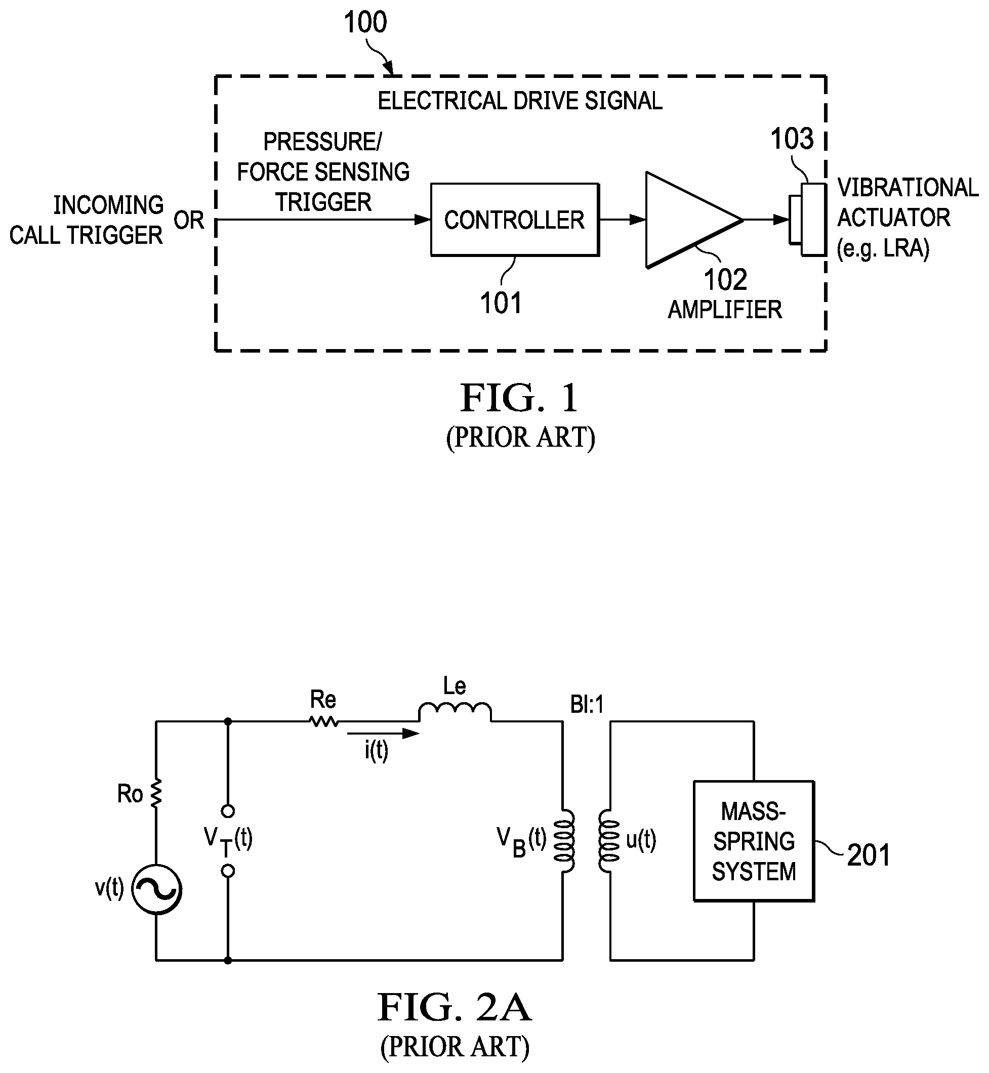
[0005] FIG. 1 illustrates an example of a vibro-haptic system in a device 100. Device 100 may comprise a controller 101 configured to control a signal applied to an amplifier 102. Amplifier 102 may then drive a haptic transducer 103 based on the signal. Controller 101 may be triggered by a trigger to output to the signal. The trigger may for example comprise a pressure or force sensor on a screen or virtual button of device 100.
[0006] Among the various forms of vibro-haptic feedback, tonal vibrations of sustained duration may play an important role to notify the user of the device of certain predefined events, such as incoming calls or messages, emergency alerts, and timer warnings, etc. In order to generate tonal vibration notifications efficiently, it may be desirable to operate the haptic actuator at its resonance frequency.
[0007] The resonance frequency f.sub.0 of a haptic transducer may be approximately estimated as:
f 0 = 1 2 * .pi. * C * M ( 1 ) ##EQU00001##
where C is the compliance of the spring system, and M is the equivalent moving mass, which may be determined based on both the actual moving part in the haptic transducer and the mass of the portable device holding the haptic transducer.
[0008] Due to sample-to-sample variations in individual haptic transducers, mobile device assembly variations, temporal component changes caused by aging, and use conditions such as various different strengths of a user gripping of the device, the vibration resonance of the haptic transducer may vary from time to time.
[0009] FIG. 2A illustrates an example of a linear resonant actuator (LRA) modelled as a linear system. LRAs are non-linear components that may behave differently depending on, for example, the voltage levels applied, the operating temperature, and the frequency of operation. However, these components may be modelled as linear components within certain conditions.
[0010] FIG. 2B illustrates an example of an LRA modelled as a linear system, including an electrically equivalent model of mass-spring system 201 of LRA. In this example, the LRA is modelled as a third order system having electrical and mechanical elements. In particular, Re and Le are the DC resistance and coil inductance of the coil-magnet system, respectively; and Bl is the magnetic force factor of the coil. The driving amplifier outputs the voltage waveform V(t) with the output impedance Ro. The terminal voltage V.sub.T (t) may be sensed across the terminals of the haptic transducer. The mass-spring system 201 moves with velocity u(t).
[0011] An electromagnetic load such as an LRA may be characterized by its impedance Z.sub.LRA as seen as the sum of a coil impedance Z.sub.coil and a mechanical impedance Z.sub.mech:
Z.sub.LRA=Z.sub.coil+Z.sub.mech (2)
[0012] Coil impedance Z.sub.coil may in turn comprise a direct current (DC) resistance Re in series with an inductance Le:
Z.sub.coil=Re+s*Le (3)
[0013] Mechanical impedance Z.sub.mech may be defined by three parameters including the resistance at resonance R.sub.RES representing an electrical resistance representative of mechanical friction of the mass-spring system of the haptic transducer, a capacitance C.sub.MES representing an electrical capacitance representative of an equivalent moving mass M of the mass-spring system of the haptic transducer, and inductance L.sub.CES representative of a compliance C of the mass-spring system of the haptic transducer. The electrical equivalent of the total mechanical impedance is the parallel connection of R.sub.RES, C.sub.MES, L.sub.CES. The Laplace transform of this parallel connection is described by:
Z m e c h ( s ) = 1 ( 1 R R E S + 1 L CES * s + c M E S * s ) ( 4 ) ##EQU00002##
[0014] The resonant frequency f.sub.0 of the haptic transducer can be represented as:
f 0 = 1 ( 2 * .pi. * L C E S * C M E S * ) ( 5 ) ##EQU00003##
[0015] The quality factor Q of the LRA can be represented as:
Q = R RES * Re R RES + R e * c MES L CES ( 6 ) ##EQU00004##
[0016] Referring to equation (6), it may appear non-intuitive that the expression involves a subexpression describing the parallel connection of resistances Re and
R R E S ( i , e . , R RES * R e R RES + R e ) ##EQU00005##
while in FIG. 2B these resistances are shown in a series connection. However, such may be the case where a driving voltage Ve is oscillating but then abruptly turns off and goes to zero. The voltage amplifier shown in FIG. 2B may be considered to have a low source impedance, ideally zero source impedance. Under these conditions, when driving voltage Ve goes to zero, the voltage amplifier effectively disappears from the circuit. At that point, the top-most terminal of resistance Re in FIG. 2B is grounded as is the bottom-most terminal of resistance R.sub.RES and so resistances Re and R.sub.RES are indeed connected in parallel as reflected in equation (6).
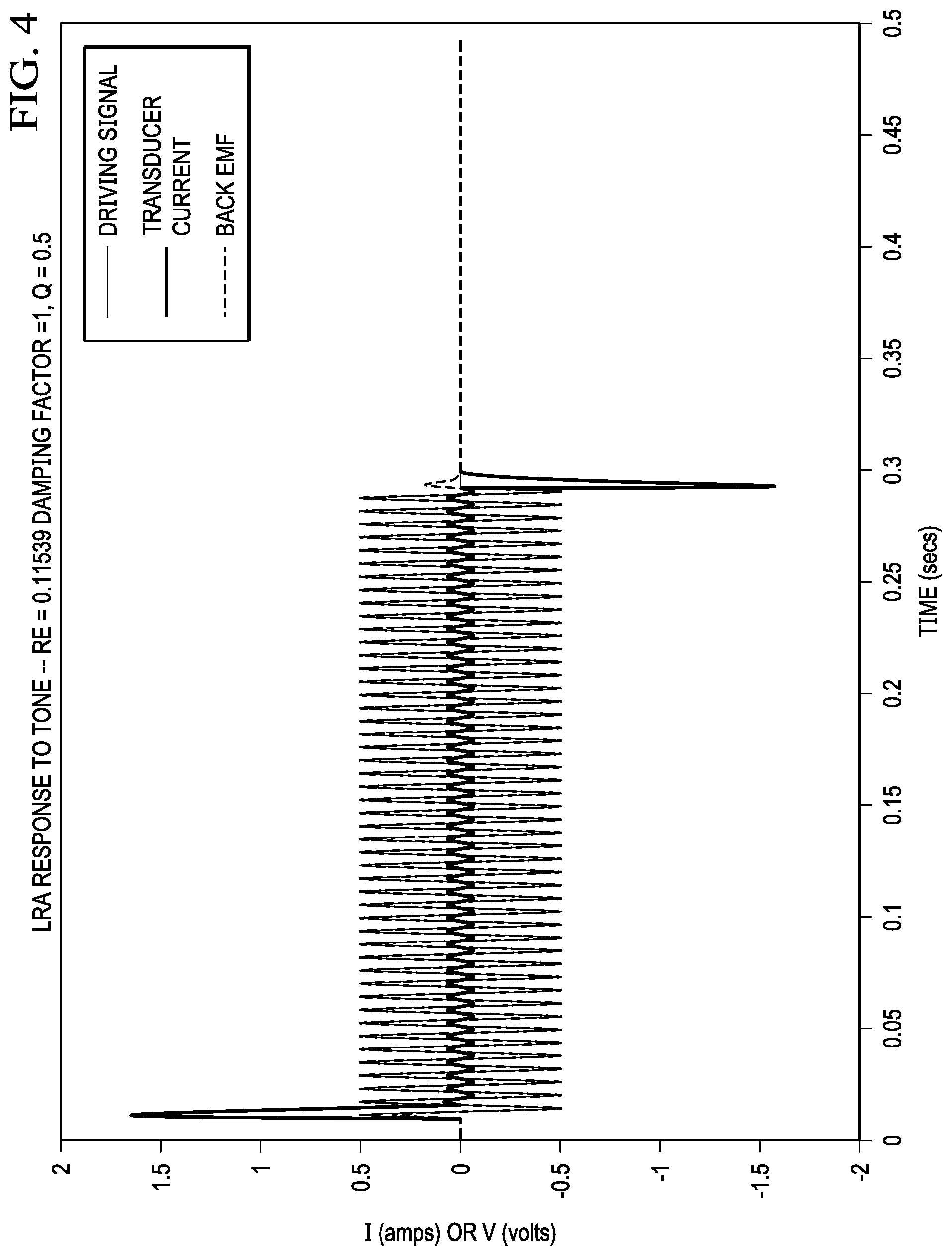
[0017] Electromagnetic transducers, such as LRAs or microspeakers, may have slow response times. FIG. 3 is a graph of an example response of an LRA, depicting an example driving signal to the LRA, a current through the LRA, and a back electromotive force (back EMF) of the LRA, wherein such back EMF may be proportional to the velocity of a moving element (e.g., coil or magnet) of the transducer. As shown in FIG. 3, the attack time of the back EMF may be slow as energy is transferred to the LRA, and some "ringing" of the back EMF may occur after the driving signal has ended as the mechanical energy stored in the LRA is discharged. In the context of a haptic LRA, such behavioral characteristic may result in a "mushy" feeling click or pulse, instead of a "crisp" tactile response. Thus, it may be desirable for an LRA to instead have a response similar to that shown in FIG. 4, in which there exists minimal ringing after the driving signal has ended, and which may provide a more "crisp" tactile response in a haptic context. Accordingly, it may be desirable to apply processing to a driving signal such that when the processed driving signal is applied to the transducer, the velocity or back EMF of the transducer more closely approaches that of FIG. 4.
SUMMARY
[0018] In accordance with the teachings of the present disclosure, the disadvantages and problems associated with undesirable dynamics of an electromagnetic load may be reduced or eliminated.
[0019] In accordance with embodiments of the present disclosure, a system may include a signal generator configured to generate a raw waveform signal and a modeling subsystem configured to implement a discrete time model of an electromagnetic load that emulates a virtual electromagnetic load and further configured to modify the raw waveform signal to generate a waveform signal for driving the electromagnetic load by modifying the virtual electromagnetic load to have a desired characteristic, applying the discrete time model to the raw waveform signal to generate the waveform signal for driving the electromagnetic load, and applying the waveform signal to the electromagnetic load.
[0020] In accordance with these and other embodiments of the present disclosure, a method may include implementing a discrete time model of an electromagnetic load that emulates a virtual electromagnetic load and modifying a raw waveform signal to generate a waveform signal for driving the electromagnetic load by modifying the virtual electromagnetic load to have a desired characteristic applying the discrete time model to the raw waveform signal to generate the waveform signal for driving the electromagnetic load, and applying the waveform signal to the electromagnetic load.
[0021] In accordance with these and other embodiments of the present disclosure, a host device may include an electromagnetic load, a signal generator configured to generate a raw waveform signal, and a modeling subsystem configured to implement a discrete time model of the electromagnetic load that emulates a virtual electromagnetic load and further configured to modify the raw waveform signal to generate a waveform signal for driving the electromagnetic load by modifying the virtual electromagnetic load to have a desired characteristic, applying the discrete time model to the raw waveform signal to generate the waveform signal for driving the electromagnetic load, and applying the waveform signal to the electromagnetic load.
[0022] Technical advantages of the present disclosure may be readily apparent to one having ordinary skill in the art from the figures, description and claims included herein. The objects and advantages of the embodiments will be realized and achieved at least by the elements, features, and combinations particularly pointed out in the claims.
[0023] It is to be understood that both the foregoing general description and the following detailed description are examples and explanatory and are not restrictive of the claims set forth in this disclosure.
BRIEF DESCRIPTION OF THE DRAWINGS
[0024] A more complete understanding of the present embodiments and advantages thereof may be acquired by referring to the following description taken in conjunction with the accompanying drawings, in which like reference numbers indicate like features, and wherein:
[0025] FIG. 1 illustrates an example of a vibro-haptic system in a device, as is known in the art;
[0026] FIGS. 2A and 2B each illustrate an example of a Linear Resonant Actuator (LRA) modelled as a linear system, as is known in the art;
[0027] FIG. 3 illustrates a graph of example waveforms of an electromagnetic load, as is known in the art;
[0028] FIG. 4 illustrates a graph of desirable example waveforms of an electromagnetic load, in accordance with embodiments of the present disclosure;
[0029] FIG. 5 illustrates an example system for improving transducer dynamics, in accordance with embodiments of the present disclosure; and
[0030] FIG. 6 illustrates an example of a Linear Resonant Actuator (LRA) modelled as a linear system and including a negative resistance, in accordance with embodiments of the present disclosure.
DETAILED DESCRIPTION
[0031] The description below sets forth example embodiments according to this disclosure. Further example embodiments and implementations will be apparent to those having ordinary skill in the art. Further, those having ordinary skill in the art will recognize that various equivalent techniques may be applied in lieu of, or in conjunction with, the embodiment discussed below, and all such equivalents should be deemed as being encompassed by the present disclosure.
[0032] Various electronic devices or smart devices may have transducers, speakers, and acoustic output transducers, for example any transducer for converting a suitable electrical driving signal into an acoustic output such as a sonic pressure wave or mechanical vibration. For example, many electronic devices may include one or more speakers or loudspeakers for sound generation, for example, for playback of audio content, voice communications and/or for providing audible notifications.
[0033] Such speakers or loudspeakers may comprise an electromagnetic actuator, for example a voice coil motor, which is mechanically coupled to a flexible diaphragm, for example a conventional loudspeaker cone, or which is mechanically coupled to a surface of a device, for example the glass screen of a mobile device. Some electronic devices may also include acoustic output transducers capable of generating ultrasonic waves, for example for use in proximity detection type applications and/or machine-to-machine communication.
[0034] Many electronic devices may additionally or alternatively include more specialized acoustic output transducers, for example, haptic transducers, tailored for generating vibrations for haptic control feedback or notifications to a user. Additionally or alternatively, an electronic device may have a connector, e.g., a socket, for making a removable mating connection with a corresponding connector of an accessory apparatus and may be arranged to provide a driving signal to the connector so as to drive a transducer, of one or more of the types mentioned above, of the accessory apparatus when connected. Such an electronic device will thus comprise driving circuitry for driving the transducer of the host device or connected accessory with a suitable driving signal. For acoustic or haptic transducers, the driving signal will generally be an analog time varying voltage signal, for example, a time varying waveform.
[0035] The problem illustrated in FIG. 3 may result from a transducer 301 with a high quality factor Q with a sharp peak in impedance at a resonant frequency f.sub.0 of the transducer.
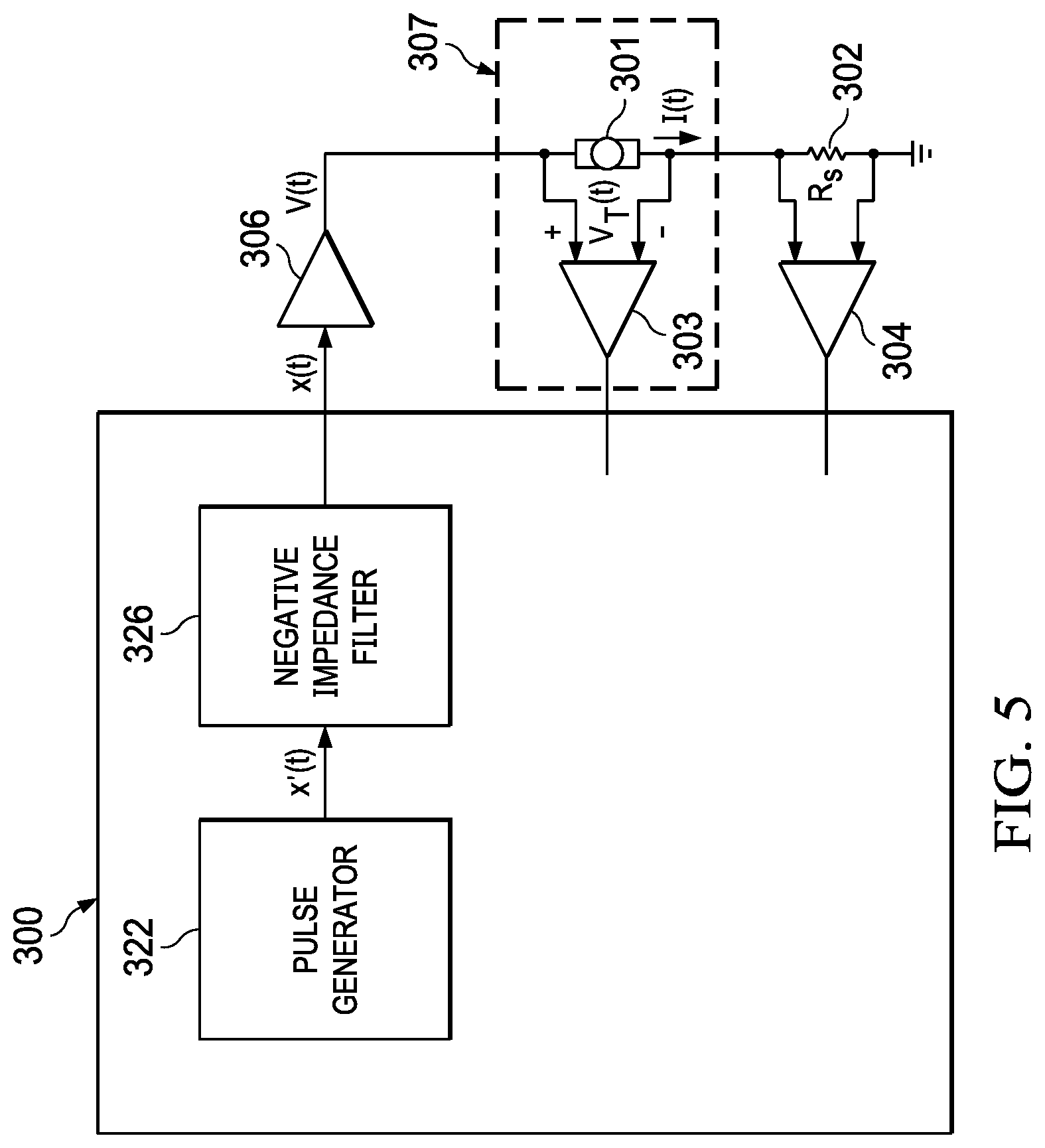
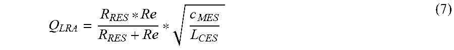
[0036] FIG. 5 illustrates example system 300 for improving dynamics of an electromagnetic load, in accordance with embodiments of the present disclosure. In some embodiments, system 300 may be integral to a host device comprising system 300 and haptic transducer 301. Such device may include, without limitation, a mobile device, home application, a vehicle, and/or any other system, device, or apparatus that includes a human-machine interface. As described in greater detail below, a system 300 may implement negative impedance filter 326 to apply to the raw transducer driving signal, which may reduce an effective quality factor Q of the transducer, which may in turn decrease attack time and minimize ringing occurring after the raw transducer driving signal has ended. Quality factor Q of a transducer may be expressed as:
Q LRA = R RES * R e R RES + R e * c MES L CES ( 7 ) ##EQU00006##
[0037] In equation (7), as DC resistance Re increases, the numerator term R.sub.RES*Re increases more rapidly than the denominator term R.sub.RES+Re. Therefore, quality factor Q.sub.LRA generally increases with increasing DC resistance Re. Accordingly, one way system 300 may minimize quality factor q is to effectively decrease DC resistance Re. In some embodiments, system 300 may ideally decrease the effective DC resistance Re to a point in which critical damping occurs in transducer 301.
[0038] FIG. 6 illustrates an example of haptic transducer 301 modelled as a linear system including electrical components 602 and electrical model of mechanical components 604 and including a negative resistance resistor 606 with negative impedance Re_neg inserted in series with haptic transducer 301, in accordance with embodiments of the present disclosure. The addition of negative impedance Re_neg may lower quality factor Q.sub.LRA because effectively it subtracts from DC resistance Re thereby reducing the overall DC electrical impedance.
[0039] In practice, negative resistors do not exist. Instead, negative impedance filter 326 may comprise a digital filter configured to behave substantially like the circuit shown in FIG. 6, including a mathematical model of negative impedance Re_neg in series with a mathematical model of haptic transducer 301. In operation, negative impedance filter 326 may in effect compute a voltage V.sub.m that would occur at the junction of negative impedance Re_neg and DC resistance Re as shown in FIG. 6, if, in fact, it were possible to place a physical resistor with negative impedance Re_neg in series with haptic transducer 301. Computed voltage V.sub.m may then be used to drive haptic transducer 301.
[0040] From an examination of FIG. 6, a Laplace transform relationship between voltage V.sub.m and a driving voltage V.sub.e may be given by
V m ( s ) = V e ( s ) * Z L R A ( s ) ( Z L R A ( s ) - Re_neg ) ( 8 ) ##EQU00007##
Equation (8) is effectively a voltage divider that outputs V.sub.m given input V.sub.e. Negative impedance filter 326 may be a digital filter that implements a digital version of the transfer function:
Z NIF ( s ) = Z L R A ( s ) ( Z L R A ( s ) - Re_neg ) ( 9 ) ##EQU00008##
[0041] Raw waveform signal x'(t) generated by pulse generator 322 and driven to negative impedance filter 326 in system 300 may correspond to a digital representation of driving voltage V.sub.e shown in FIG. 6. Waveform signal x(t) generated by negative impedance filter 326 may in turn correspond to voltage V.sub.m. Voltage V.sub.m may be input to amplifier 306, which in turn may drive haptic transducer 301.
[0042] In some embodiments, negative impedance Re_neg may be represented as a fraction of DC resistance Re:
Re_neg=Re*Re_cancel (10)
[0043] Where factor Re_cancel may comprise a unitless value between 0 and 1, and may be chosen a-priori, representing the fraction of DC resistance Re that is to be cancelled by negative impedance filter 326.
[0044] Negative impedance filter 326 may implement a digital filter with transfer function corresponding to equation (9). Assuming that negative impedance Re_neg is given by equation (10), then implementation of negative impedance filter 326 as a digital filter may require a digital estimate of transducer impedance Z.sub.LRA, DC resistance Re, and an a-priori choice for factor Re_cancel.
[0045] Negative impedance filter transfer function may be a third-order digital filter with z-transform represented as:
Z NIF ( z ) = b 0 _nif + b 1 _nif * z - 1 + b 2 _nif * z - 2 + b 3 _nif * z - 3 1 + a 1 _nif * z - 1 + a 2 _nif * z - 2 + a 3 _nif * z - 3 ( 11 ) ##EQU00009##
The coefficients b0_nif, b1_nif, b2_nif, b3_nif, a1_nif, a2_nif, and a3_nif of negative impedance filter 326 may embody the information about transducer impedance Z.sub.LRA, DC resistance Re, and factor Re_cancel.
[0046] Example methods and systems for online real-time estimation of parameters of haptic transducer impedance Z.sub.LRA are described in U.S. Provisional Patent Application Ser. No. 62/826,388, filed Mar. 29, 2019, and in any application claiming priority thereto, all of which are incorporated by reference in their entireties, and may be referred to herein as the "Estimating Patent Application" and is incorporated by reference in its entirety.
[0047] In the "Estimating Patent Application," a method is described that separates the estimation problem into an estimation of coil impedance Z.sub.coli=Re+Le*s on the one hand and estimation of mechanical impedance Z.sub.mech on the other. In particular, the electrical equivalent of mechanical impedance Z.sub.mech may be estimated using least-squares estimation as a second-order system which is then placed in series with coil impedance Z.sub.coil to determine a third-order haptic transducer impedance Z.sub.LRA. In the "Estimating Patent Application," a second-order mechanical impedance Z.sub.mech may be estimated from three least-squares parameter estimates: g, a1, and a2. A full haptic transducer impedance Z.sub.LRA may then be estimated from these three parameters plus separately estimated DC coil resistance Re and coil inductance Le.
Z L R A = V L R A ( s ) l L R A ( s ) ##EQU00010##
is a transfer function that may describe a filter that takes current as input and produces a voltage as output. However, it may desirable to find parameters b0_nif, b1_nif, b2_nif, b3_nif, a1_nif, a2_nif, and a3_nif for negative impedance filter 326 that describes a voltage divider that takes V.sub.e (z)=V.sub.LRA(z) input and produces voltage V.sub.m(z) as output. By using equation (9) from above and knowledge of separately estimated DC coil resistance Re (e.g., it may be assumed that coil inductance Le is fixed and estimated a-priori by laboratory measurements or other means), expressions for negative impedance filter 326 may be provided. Substituting the expressions for haptic transducer impedance Z.sub.LRA involving g, a1, a2 and Re from the "Estimating Patent Application" into equation (9) above, and applying the Bilinear Transform to convert from continuous time to discrete (digital) time, expressions for parameters b0_nif, b1_nif, b2_nif, b3_nif, a1_nif, a2_nif, and a3_nif may be derived for negative impedance filter 326. An inductance Le_nrm and an impedance Zfb may be defined by:
Le_nrm=2*Le*fs;
Zfb=Re_cancel*Re;
[0048] Unnormalized coefficients for the negative impedance filter 326 may be defined as:
b0_nif=-Le_nrm-Re-g;
b1_nif=Le_nrm-Re-g-Le_nrm*a1-Re*a1;
b2_nif=g+Le_nrm*a1-Le_nrm*a2-Re*a1-Re*a2;
b3_nif=g+Le_nrm*a-Re*a2;
a0_nif=Zfb-Le_nrm-Re-g;
a1_nif=Zfb+Le_nrm-Re-g+Zfb*a1-Le_nrm*a1-Re*a1;
a2_nif=g+Zfb*a1+Zfb*a2+Le_nrm*a1-Le_nrm*a2-Re*a1-Re*a2;
and
a3_nif=g+Zfb*a2+Le_nrm*a2-Re*a2.
[0049] All of these expressions may further be normalized by dividing the above coefficients by a0_nif to arrive at final parameter coefficients b0_nif, b1_nif, b2_nif, b3_nif, a1_nif, a2_nif, and a3_nif of negative impedance filter 326.
[0050] The transfer function of negative impedance filter 326 may be a third-order digital filter with a z-transform represented as:
Z NIF ( z ) = b 0 _nif + b 1 _nif * z - 1 + b 2 _nif * z - 2 + b 3 _nif * z - 3 1 + a 1 _nif * z - 1 + a 2 _nif * z - 2 + a 3 _nif * z - 3 ( 12 ) ##EQU00011##
wherein coefficients b0_nif, b1_nif, b2_nif, b3_nif, a1_nif, a2_nif, and a3_nif of negative impedance filter 326 embody information about transducer impedance Z.sub.LRA, DC resistance Re, and factor Re_cancel.
[0051] In some embodiments, knowledge of the electrical and electrical equivalent transducer parameters Re, Le, R.sub.RES, C.sub.MES, L.sub.CES may be obtained offline. This knowledge may result from laboratory measures of a transducer device and/or from data published by a transducer manufacturer.
[0052] The expression for the transfer function of negative impedance filter 326 function given in equation (9) is in the form of an s-domain Laplace transform. Such expression may be converted to a digital z-transform using any number of standard techniques such as the Bilinear Transform, the Impulse Invariant Transform, and others.
[0053] By substituting equation (2) for transducer impedance Z.sub.LRA and equation (10) for negative resistance Re_neg in equation (9), the transfer function of negative impedance filter 326 may be expressed as
Z NIF ( s ) = Z coil ( s ) + Z mech ( s ) ( Z coil ( s ) + Z m e c h ( s ) - R e * Re_cancel ) ( 13 ) ##EQU00012##
[0054] Further substituting equation (3) for Z.sub.coil (s) and equation (4) for Z.sub.mech(s) gives:
Z NIF ( s ) = R e + s * Le + ( 1 ( 1 R REE + 1 L CES * s + c MES * s ) ) ( Re + s * Le + ( 1 ( 1 R REE + 1 L CES * s + c MES * s ) ) - Re * Re_cancel ) ( 14 ) ##EQU00013##
[0055] Equation (13) may thus provide an expression for the Laplace transform of the transfer function Z.sub.NIF (s) of negative impedance filter 326 in terms of the electrical and electrical equivalent parameters Re, Le, R.sub.RES, C.sub.MES, C.sub.MES, L.sub.CES as well as factor Re_cancel. To transform equation (14) to a digital filter z-transform using the Bilinear Transform, the Laplace variable s may be substituted according to:
s = 2 * f s * ( z - 1 ) ( z + 1 ) ( 15 ) ##EQU00014##
[0056] If equation (15) is substituted into equation (14) and then simplified, an equation for the digital z-transform Z.sub.NIF(z) is obtained in the form of equation (12), where the coefficients b0_nif, b1_nif, b2_nif, b3_nif, a1_nif, a2_nif, and a3_nif are expressed in terms of Re, Le, R.sub.RES, C.sub.MES, L.sub.CES as well as factor Re_cancel, according to:
b0_nif=(Re*Rres+2*Lces*Re*fs+2*Lces*Rres*fs+2*Le*Rres*fs+4*Lces*Le*fs.su- p.2+8*Cmes*Lces*Le*Rres*fs.sup.3+4*Cmes*Lces*Re*Rres*fs.sup.2)/(Re*Rres-Re- *Re_cancel*Rres+2*Lces*Re*fs+2*Lces*Rres*fs+2*Le*Rres*fs+4*Lces*Le*fs.sup.- 2-2*Lces*Re*Re_cancel*fs+8*Cmes*Lces*Le*Rres*fs.sup.3+4*Cmes*Lces*Re*Rres*- fs.sup.2-4*Cmes*Lces*Re*Re_cancel*Rres*fs.sup.2);
b1_nif=(3*Re*Rres+2*Lces*Re*fs+2*Lces*Rres*fs+2*Le*Rres*fs-4*Lces*Le*fs.- sup.2-24*Cmes*Lces*Le*Rres*fs.sup.3-4*Cmes*Lces*Re*Rres*fs.sup.2)/(Re*Rres- -Re*Re_cancel*Rres+2*Lces*Re*fs+2*Lces*Rres*fs+2*Le*Rres*fs+4*Lces*Le*fs.s- up.2-2*Lces*Re*Re_cancel*fs+8*Cmes*Lces*Le*Rres*fs.sup.3+4*Cmes*Lces*Re*Rr- es*fs.sup.2-4*Cmes*Lces*Re*Re_cancel*Rres*fs.sup.2);
b2_nif=-(2*Lces*Re*fs-3*Re*Rres+2*Lces*Rres*fs+2*Le*Rres*fs+4*Lces*Le*fs- .sup.2-24*Cmes*Lces*Le*Rres*fs.sup.3-4*Cmes*Lces*Re*Rres*fs.sup.3)/(Re*Rre- s-Re*Re_cancel*Rres+2*Lces*Re*fs+2*Lces*Rres*fs+2*Le*Rres*fs+4*Lces*Le*fs.- sup.2-2*Lces*Re*Re_cancel*fs+8*Cmes*Lces*Le*Rres*fs.sup.3+4*Cmes*Lces*Re*R- res*fs.sup.2-4*Cmes*Lces*Re*Re_cancel*Rres*fs.sup.2);
b3_nif=-(2*Lces*Re*fs-Re*Rres+2*Lces*Rres*fs+2*Le*Rres*fs-4*Lces*Le*fs.s- up.2+8*Cmes*Lces*Le*Rres*fs.sup.3-4*Cmes*Lces*Re*Rres*fs.sup.2)/(Re*Rres-R- e*Re_cancel*Rres+2*Lces*Re*fs+2*Lces*Rres*fs+2*Le*Rres*fs+4*Lces*Le*fs.sup- .2-2*Lces*Re*Re_cancel*fs+8*Cmes*Lces*Le*Rres*fs.sup.3+4*Cmes*Lces*Re*Rres- *fs.sup.2-4*Cmes*Lces*Re*Re_cancel*Rres*fs.sup.2);
a1_nif=(3*Re*Rres-3*Re*Re_cancel*Rres+2*Lces*Re*fs+2*Lces*Rres*fs+2*Le*R- res*fs-4*Lces*Le*fs.sup.2-2*Lces*Re*Re_cancel*fs 24*Cmes*Lces*Le*Rres*fs.sup.3-4*Cmes*Lces*Re*Rres*fs.sup.2-4*Cmes*Lees*Re- *Re_cancel*Rres*fs.sup.2)/(Re*Rres-Re*Re_cancel*Rres+2*Lces*Re*fs+2*Lces*R- res*fs+2*Le*Rres*fs+4*Lces*Le*fs.sup.2-2*Lces*Re*Re_cancel*fs+8*Cmes*Lees*- Le*Rres*fs.sup.3+4*Cmes*Lces*Re*Rres*fs.sup.2-4*Cmes*Lces*Re*Re_cancel*Rre- s*fs.sup.2);
a2_nif=-(3*Re*Re_cancel*Rres-3*Re*Rres+2*Lces*Re*fs+2*Lces*Rres*fs+2*Le*- Rres*fs-4*Lces*Le*fs.sup.2-2*Lces*Re*Re_cancel*fs-24*Cmes*Lces*Le*Rres*fs.- sup.3+4*Cmes*Lees*Re*Rres*fs.sup.2-4*Cmes*Lces*Re*Re_cancel*Rres*fs.sup.2)- /(Re*Rres Re*Re_cancel*Rres+2*Lces*Re*fs+2*Lces*Rres*fs+2*Le*Rres*fs+4*Lce- s*Le*fs.sup.2-2*Lces*Re*Re_cancel*fs+8*Cmes*Lces*Le*Rres*fs.sup.3+4*Cmes*L- ces*Re*Rres*fs.sup.2-4*Cmes*Lces*Re*Re_cancel*Rres*fs.sup.2)
a3_nif=-(Re*Re_cancel*Rres-Re*Rres+2*Lces*Re*fs+2*Lces*Rres*fs+2*Le*Rres- *fs-4*Lces*Le*fs.sup.2-2*Lces*Re*Re_cancel*fs+8* *Cmes*Lces*Le*Rres*fs.sup.3-4*Cmes*Lces*Re*Rres*fs.sup.2+4*Cmes*Lces*Re*R- e_cancel*Rres*fs.sup.2)/(Re*Rres-Re*Re_cancel*Rres+2*Lces*Re*fs+2*Lces*Rre- s*fs+2*Le*Rres*fs+4*Lces*Le*fs.sup.2-2*Lces*Re*Re_cancel*fs+8*Cmes*Lces*Le- *Rres*fs.sup.3+4*Cmes*Lees*Re*Rres*fs.sup.2-4*Cmes*Lces*Re*Re_cancel*Rres*- fs.sup.2)
[0057] In embodiments in which parameters Re, Le, R.sub.RES, C.sub.MES, L.sub.CES as well as factor Re_cancel are obtained offline, the expressions above may be used to compute the coefficients for the negative impedance filter 326.
[0058] Although the foregoing discusses application to a linear electromagnetic load, it is understood that systems and methods similar or identical to those disclosed may be applied to other linear or non-linear systems.
[0059] Further, although the foregoing contemplates use of a negative resistance filter to implement a model of an LRA, in some embodiments a mathematical equivalent to an LRA may be used in lieu of a model.
[0060] Accordingly, using the systems and methods described above, a system (e.g., system 300) may include a signal generator (e.g., pulse generator 322) configured to generate a raw waveform signal (e.g., raw waveform signal x'(t)) and a modeling subsystem (e.g., negative impedance filter 326) configured to implement a discrete time model (e.g., model shown in FIG. 6) of an electromagnetic load (e.g., haptic transducer 301) that emulates a virtual electromagnetic load and further configured to modify the raw waveform signal to generate a waveform signal (e.g., waveform signal x(t)) for driving the electromagnetic load by modifying the virtual electromagnetic load to have a desired characteristic (e.g., applying negative resistance 606), applying the discrete time model to the raw waveform signal to generate the waveform signal for driving the electromagnetic load, and applying the waveform signal to the electromagnetic load.
[0061] As used herein, when two or more elements are referred to as "coupled" to one another, such term indicates that such two or more elements are in electronic communication or mechanical communication, as applicable, whether connected indirectly or directly, with or without intervening elements.
[0062] This disclosure encompasses all changes, substitutions, variations, alterations, and modifications to the example embodiments herein that a person having ordinary skill in the art would comprehend. Similarly, where appropriate, the appended claims encompass all changes, substitutions, variations, alterations, and modifications to the example embodiments herein that a person having ordinary skill in the art would comprehend. Moreover, reference in the appended claims to an apparatus or system or a component of an apparatus or system being adapted to, arranged to, capable of, configured to, enabled to, operable to, or operative to perform a particular function encompasses that apparatus, system, or component, whether or not it or that particular function is activated, turned on, or unlocked, as long as that apparatus, system, or component is so adapted, arranged, capable, configured, enabled, operable, or operative. Accordingly, modifications, additions, or omissions may be made to the systems, apparatuses, and methods described herein without departing from the scope of the disclosure. For example, the components of the systems and apparatuses may be integrated or separated. Moreover, the operations of the systems and apparatuses disclosed herein may be performed by more, fewer, or other components and the methods described may include more, fewer, or other steps. Additionally, steps may be performed in any suitable order. As used in this document, "each" refers to each member of a set or each member of a subset of a set.
[0063] Although exemplary embodiments are illustrated in the figures and described below, the principles of the present disclosure may be implemented using any number of techniques, whether currently known or not. The present disclosure should in no way be limited to the exemplary implementations and techniques illustrated in the drawings and described above.
[0064] Unless otherwise specifically noted, articles depicted in the drawings are not necessarily drawn to scale.
[0065] All examples and conditional language recited herein are intended for pedagogical objects to aid the reader in understanding the disclosure and the concepts contributed by the inventor to furthering the art, and are construed as being without limitation to such specifically recited examples and conditions. Although embodiments of the present disclosure have been described in detail, it should be understood that various changes, substitutions, and alterations could be made hereto without departing from the spirit and scope of the disclosure.
[0066] Although specific advantages have been enumerated above, various embodiments may include some, none, or all of the enumerated advantages. Additionally, other technical advantages may become readily apparent to one of ordinary skill in the art after review of the foregoing figures and description.
[0067] To aid the Patent Office and any readers of any patent issued on this application in interpreting the claims appended hereto, applicants wish to note that they do not intend any of the appended claims or claim elements to invoke 35 U.S.C. .sctn. 112(f) unless the words "means for" or "step for" are explicitly used in the particular claim.
* * * * *
D00000
D00001
D00002
D00003
D00004
D00005
D00006


XML
uspto.report is an independent third-party trademark research tool that is not affiliated, endorsed, or sponsored by the United States Patent and Trademark Office (USPTO) or any other governmental organization. The information provided by uspto.report is based on publicly available data at the time of writing and is intended for informational purposes only.
While we strive to provide accurate and up-to-date information, we do not guarantee the accuracy, completeness, reliability, or suitability of the information displayed on this site. The use of this site is at your own risk. Any reliance you place on such information is therefore strictly at your own risk.
All official trademark data, including owner information, should be verified by visiting the official USPTO website at www.uspto.gov. This site is not intended to replace professional legal advice and should not be used as a substitute for consulting with a legal professional who is knowledgeable about trademark law.