Used Oil Recycling and Pretreatment Filtration Assembly
KUTOWY; Oleh ; et al.
U.S. patent application number 15/555535 was filed with the patent office on 2020-10-01 for used oil recycling and pretreatment filtration assembly. This patent application is currently assigned to Mempore Corp. The applicant listed for this patent is Mempore Corp. Invention is credited to Liubomyr KUTOWY, Oleh KUTOWY.
| Application Number | 20200306697 15/555535 |
| Document ID | / |
| Family ID | 1000004888785 |
| Filed Date | 2020-10-01 |


View All Diagrams
| United States Patent Application | 20200306697 |
| Kind Code | A1 |
| KUTOWY; Oleh ; et al. | October 1, 2020 |
Used Oil Recycling and Pretreatment Filtration Assembly
Abstract
A filtration system suitable for recovering base stock from used lubricating oil and other applications passes feedstock over nano-filtration membranes in a serpentine flow. Pressure boosters installed in the openings separating consecutive stacks serve to restore lost pressure of the feedstock. As pretreatment a "knocking" non-blinding filter separates particulates from a feedstock by a knocking action that dislodges particulate matter which has come to rest on the screen. Further pretreatment includes a vacuum evaporator for flash evaporation of volatile components from a liquid and effecting the extraction of water and glycol from used engine lubricating oil. The liquid is heated or cooled when flowing over some of the surfaces to adjust for heat lost or acquired during exposure of the liquid surface to a gas or vacuum. Liquid moves on the surface of the discs under centrifugal force or a wiper blade guides the liquid as it moves over the support surface.
| Inventors: | KUTOWY; Oleh; (North Gower, CA) ; KUTOWY; Liubomyr; (Kemptville, CA) | ||||||||||
| Applicant: |
|
||||||||||
|---|---|---|---|---|---|---|---|---|---|---|---|
| Assignee: | Mempore Corp North Gower ON |
||||||||||
| Family ID: | 1000004888785 | ||||||||||
| Appl. No.: | 15/555535 | ||||||||||
| Filed: | March 2, 2016 | ||||||||||
| PCT Filed: | March 2, 2016 | ||||||||||
| PCT NO: | PCT/CA2016/000058 | ||||||||||
| 371 Date: | June 18, 2018 |
Related U.S. Patent Documents
| Application Number | Filing Date | Patent Number | ||
|---|---|---|---|---|
| 14997143 | Jan 15, 2016 | 9993775 | ||
| 15555535 | ||||
| Current U.S. Class: | 1/1 |
| Current CPC Class: | B01D 61/12 20130101; B01D 2311/14 20130101; B01D 63/082 20130101; B01D 2319/022 20130101; B01D 2311/04 20130101; B01D 2313/08 20130101; B01D 2313/143 20130101; B01D 61/08 20130101; B01D 2311/06 20130101; B01D 2319/025 20130101; B01D 2313/18 20130101; B01D 2313/146 20130101; B01D 61/027 20130101; B01D 2315/10 20130101 |
| International Class: | B01D 63/08 20060101 B01D063/08; B01D 61/12 20060101 B01D061/12; B01D 61/08 20060101 B01D061/08 |
Foreign Application Data
| Date | Code | Application Number |
|---|---|---|
| Mar 3, 2015 | CA | 2883468 |
Claims
1. A filtration system to produce a permeate from a feedstock comprising multiple permeable membrane support panels each carrying respective membranes, each support panel having a receiving space within to serve as a cavity for accepting permeate driven through the membranes by pressure applied to the feedstock and a permeate-receiving cavity outlet to drain-off permeate, wherein a) the multiple membrane support panels are mounted in a common pressure-containing vessel having a feedstock inlet and outlets for permeate and concentrate, and b) the pressure vessel contains at least one pressure-sustaining separator plate positioned between at least two adjacent membrane support panels, the separator plate having a flow-through opening at one end to allow fluid to flow from one membrane support panel to the next.
2. The filtration system as in claim 1 wherein the at least two adjacent membrane support panels are positioned on opposite sides of the separator plate so as to reverse the direction of feedstock flow over the consecutive membrane support panels on either side of the separator plate.
3. The filtration system as in claim 1 wherein: a) the support panels comprise two permeable panels mounted back-to-back with two respective membranes located on their outer-facing surfaces, and b) the two panels define between them the receiving space there within to serve as the cavity for accepting permeate driven through the two membranes by pressure applied to the feedstock, thereby constituting "panel assemblies".
4. The filtration system as in claim 3 wherein, between separator plates, groups of panel assemblies are arrayed in a parallel configuration so that feedstock will flow in the same direction on both sides of the panel assemblies within the group, collectively the panel assemblies in a group constituting a "stack" of panel assemblies separated by the separator plates.
5. The filtration system as in claim 4 wherein the pressure vessel contains three or more stacks of panel assemblies, each consecutive stack being separated from an adjacent stack of panel assemblies by a pressure-sustaining separator plate, each separator plate having a flow-through opening at one end to allow fluid to flow from one stack of panel assemblies to the next.
6. A filtration system as in claim 5 comprising a pressure booster mounted in at least one separator plate flow-through opening to restore lost pressure between consecutive stacks of panel assemblies.
7. A filter system as in claim 6 comprising pressure boosters respectively mounted in the flow-through openings in every other separator plate.
8. A filter system as in claim 7 comprising pressure boosters respectively mounted in the flow-through openings in every separator plate.
9. A filter system as in claim 6 wherein the pressure booster is actuated by an electric motor.
10. A filter system as in claim 7 wherein the pressure boosters are actuated by respective electric motors.
11. A filter system as in claim 8 wherein the pressure boosters are actuated by respective electric motors.
12. A filter system as in claim 6 wherein the pressure booster is actuated by a rotating shaft driven from outside the pressure vessel.
13. A filtration system as in claim 7 wherein the pressure boosters are actuated by a common rotating shaft driven from outside the pressure vessel.
14. A filtration system as in claim 8 wherein the pressure boosters are actuated by a common rotating shaft driven from outside the pressure vessel.
15. A filtration system as in claim 13 wherein the common shaft penetrates intervening separator plate through a pressure seal.
16. A filtration system as in claim 5 comprising respective frames within which each membrane panel assembly is mounted, the frames, when the membrane panel assemblies are combined to form stacks, serving as part of the walls of the pressure containment vessel, wherein the frames provide a manifold connected to the permeate outlets of the permeate receiving cavities of each membrane panel assembly for collection of permeate for delivery to an external storage vessel.
17. A filtration system as in claim 16 wherein separator plates interspersed between the stacks of panel assemblies and serving as part of the walls of the pressure containment vessel are respectively provided with conduits connected to the manifolds of the frames to receive and convey permeate out of the pressure containment vessel.
18. A filtration system as in claim 4 wherein the permeate-receiving cavity outlets of each panel assembly in a stack are connected to a stack manifold that is connected to deliver permeate to a back-pressure control valve having an associated pressure sensor and valve control system for establishing the pressure within the permeate-receiving cavity.
19. A filtration system as in claim 4 wherein the permeate-receiving cavity outlets of each panel assembly in a stack are connected to a stack manifold that is connected through passageways formed in a separator plate at the end of the stack to deliver permeate to a back-pressure control valve having an associated pressure sensor and valve control system for establishing the pressure within the permeate-receiving cavity.
20. A "knocking" non-blinding filter for extracting a filtrate from a feedstock comprising: a. a resiliently supported frame in turn supporting a durable, permeable screen or mesh that is oriented at a flow-supporting downwardly inclined angle, b. an entry region for receiving the feedstock at the upper end of the frame from which the feedstock will flow down the inclined screen to the base end of the frame, c. a catching container positioned beneath the screen for capturing the filtrate passing through the screen, and d. an actuator coupled to the frame to apply a force with a component for displacing the frame in a generally horizontal direction, or in a direction aligned with the upward incline of the screen, with a "knocking" action whereby the force applies a rapid onset of acceleration to the screen that assists in dislodging non-penetrating particulate material resting thereon.
21. A filter as in claim 20 a return displacement mechanism for causing the filter to thereafter return to its original location after the frame has been displaced by the knocking action.
22. A filter as in claim 20 wherein motion of the screen is cyclical and the actuator applies an acceleration to the screen at one stage in the cycle wherein the acceleration so applied is greater than the absolute value of any other acceleration or deceleration occurring during the cycle.
23. A filter as in claim 20 wherein the applied acceleration is at least 1.5 times the absolute value of any other acceleration or deceleration occurring during the cycle.
24. A filter as in claim 20 comprising an actuator coupled to the frame to generate the accelerating force, such actuator being selected from the following class: a) an electrical solenoid b) a hammer carried on a rotating support c) mechanical linkages coupled to a rotating drive d) an off-center mass carried by a rotating drive.
25. A filter as in claim 21 wherein the return displacement mechanism comprises one or more springs or resilient elements to return the displaced screen to its original location.
26. A filter as in claim 20 wherein the filter is a filter of steel mesh.
27. A filter as in claim 26 wherein the filter is a stainless steel mesh with openings smaller than 200 microns.
28. A filter as in claim 20 wherein the force accelerating the screen achieves an acceleration of 0.3 g to 5 g over at least a short length of its travel.
29. A filter as in claim 20 wherein the force applied to the frame oscillates with a frequency of 1 per 5 seconds to 20 per second.
30. A gas-liquid exchange interface apparatus for effecting chemical or physical exchanges between a gas and a liquid or evaporation of gas from the liquid comprising: a) a containment for maintaining inner components in a gas-tight, pressure controlled environment; b) a liquid inlet to the containment for introducing the liquid into the containment; c) a segmented, vertical cascade of support surfaces positioned within the containment in the form of a column of segments 220 wherein a first support surface within each segment is positioned: i) to receive the liquid from the liquid inlet onto a central region of the first support surface, and ii) to allow the liquid, when present and so deposited, to flow radially outward from the central region to and beyond the periphery of the first support surface; and iii) to expose liquid flowing over the first support surface for release of volatiles or for carrying-out a gas-liquid reaction; Liquid flowing over the second support surface is uncovered for exposure to release volatiles or carry-out a gas-liquid reaction. d) each segment providing a peripheral receiving surface and transfer passageway to transfer such liquid leaving the first support surface for deposition onto a second support surface for further inward radial flow over such second support surface towards the central area of the second support surface; e) a central opening in the central area of the second support surface positioned to direct the liquid onto the central region of the first support surface of the next consecutive segment, f) a gas outlet on the containment for introducing or evacuating gases present therein or volatile components evaporated from the liquid, g) a liquid outlet from the containment for evacuating a residual portion of the liquid, h) a liquid distributor means within each segment for inducing liquid deposited on the central region of the first support surface to flow radially outward from the central region, i) a liquid gathering means for the second surface to draw liquid towards the central region of the second support surface, and j) a thermal control source positioned within at least some of the segments for heating or cooling the liquid passing over the second surface.
31. An apparatus as in claim 30 wherein the thermal control source is positioned between the first and second surfaces within the segments for heating or cooling the liquid passing over the second surface.
32. An apparatus as in claim 30 wherein the thermal control source comprises electrically insulated electrical resistance wires in thermal connection with the second support surface.
33. An apparatus as in claim 31 wherein the thermal control source comprises tubing in thermal connection with the second support surface for carrying a heat transfer fluid to either heat or cool the second surface and liquid flowing thereon, when present.
34. An apparatus as in any one of claim 30, 31, 32 or 33 comprising: a) a temperature sensor positioned within at least some of the segments having a thermal control source to detect the temperature of the liquid, when present, as it passes through the segment, and b) a temperature controller coupled to the temperature sensor and connected for controlling the rate of delivery of heat transfer by the thermal source to such segments.
35. An apparatus as claim 34 wherein the controller operates to transfer a differing quantity of heat to at least one segment than to another segment in the column.
36. An apparatus as claim 34 wherein the controller operates to deliver greater heat to lower segments in the column to raise the temperature therein.
37. A process of using the apparatus of claim 34 wherein, by sensing the temperature of the liquid in at least two segments of the column while the liquid proceeds through the column the controller controls the rate of transfer of heat to or from the second surfaces of such segments to provide heat flow at different rates to the respective segments.
38. An apparatus as in claim 30 wherein within at least some of the segments the liquid distributor means comprises a rotatable central shaft having a central axis connected to the first support surface for rotating the first support surface within the containment and thereby inducing radial flow of the liquid when deposited thereon,
39. An apparatus as claim 38 wherein each segment comprises: a) the first support surface being in the form of a spinable disc with a circumferential perimeter, the discs in the respective segments being mounted on the rotatable central shaft, and b) the peripheral receiving surface and transfer passageway include an upright circumferential liquid catching sidewall connected to and serving as an upright sidewall for the second surface and serving to deliver liquid to the second support surface.
40. An apparatus as in claim 38 or 39 wherein in at least some of the segments of the first support surface are perforated to allow fluid to pass there through and travel radially outwardly on the underside of such first support surface while being held in place by surface tension.
41. An apparatus as in claim 38 or 39 wherein in at least some of the segments the first support surface comprises a screen portion that is permeable to permit liquid to pass there through and travel radially outwardly on the underside of such surface while being held in place by surface tension.
42. An apparatus as in claim 41 wherein the first support surface is conically shaped and oriented to be opening upwardly so as to bias liquid to pass through the screen for outward travel on the underside of such surface.
43. An apparatus as in claim 30 wherein within at least some of the segments the liquid distributor means comprises a wiping blade mounted on a central rotating shaft having a central axis for rotating the wiping blade to sweep over the first support surface and induce outward radial flow of the liquid when deposited thereon.
44. An apparatus as in claim 30 wherein within at least some of the segments the liquid distributor means comprises a wiping blade mounted on a central rotating shaft having a central axis for rotating the wiping blade to sweep over the second support surface and induce inward radial flow of the liquid when deposited thereon.
45. An apparatus as in claim 38 wherein within at least some of the segments the liquid distributor means comprises a wiping blade mounted on the central rotating shaft for rotating the wiping blade to sweep over the second support surface and induce inward radial flow of the liquid when deposited thereon.
46. An apparatus as in claim 45 wherein the wiping blade is mounted on the central rotating shaft through a speed reducing connector.
47. An apparatus as any one of claim 44, 45 or 46 wherein the portions of the second support surface conveying the liquid towards its central region are downwardly inclined and generally conically formed to induce the inward radial flow of the liquid, when present, over the second support surface towards the central area of the second support surface.
48. An apparatus as in claim 30 in combination with a gas evacuation pump connected through the gas outlet to maintain the pressure controlled environment within the containment at a sub atmospheric pressure level.
49. An apparatus as in claim 30 wherein the containment comprises a gas inlet for injecting reaction gas or sweep gas into the containment.
50. An apparatus as in claim 30 wherein the containment comprises a liquid level sensor positioned to detect the level of liquid accumulated within the containment in combination with a liquid level controller connected thereto and further operatively connected to a liquid extraction pump for intermittent removal of liquid from the containment in accordance with the status of the liquid level in the containment.
Description
FIELD OF THE INVENTION
[0001] The invention relates to an apparatus for separating fluid mixtures by filtration membranes which are arranged into membrane stacks in a supporting frame. More specifically this invention describes equipment and procedures using nano-filtration membranes for cleaning used oil to bring it back to a starting base stock for possible reuse. The invention also has applications in other fields where a filtrate or permeate is to be extracted from a feedstock. This includes, for example, dewatering food-containing liquids to produce concentrates and the purification of gelatin to high standards. Other applications include separating lighter hydrocarbons from heavier hydrocarbons in the petroleum industry.
[0002] Prior to membrane treatment the feed stock typically requires pre-treatment to remove interfering impurities and undesirable components.
[0003] This invention also describes equipment and procedures for reacting a liquid with a gas, particularly in cases where the liquid has to be progressively heated or cooled to sustain the reaction. Particularly it addresses physical reactions whereby volatile components are evaporated from a liquid. More generally this invention addresses an apparatus and process based upon processing a liquid through a stacked array of segments formed as a column wherein a chemical or physical reaction and a heat transfer process occur in consecutive stages.
[0004] "Vacuum" as used herein does not necessarily mean a high or hard vacuum but includes below atmospheric absolute pressures that are conducive to promoting vaporization. "Distilland" means the liquid undergoing treatment in such application.
[0005] Other applications include the reaction of a gas with a liquid by a chemical process which may be endothermic or exothermic where providing multiple stages of heat transfer to the liquid is conducive to sustaining the reaction.
[0006] As a further feature for pretreating feedstock this invention describes equipment and procedures for filtering particulates from a liquid or a flowable mass of larger particles. More specifically, it is applicable to a stage in the processing of used lubrication oil to recover a starting base stock for possible reuse. The filter which is agitated by "knocking" in order to improve its filtration performance.
BACKGROUND TO THE INVENTION
[0007] A useful technology for recovering usable base stock from used lube oil can employ nano-filtration membranes. Colloquially, a process based upon use of open osmosis membranes can be referred to as "nano-filtration". However use of such membranes is distinguishable from "filtration" in the following respects: separation of fluids takes place at the membrane surface based on attractions and repulsions of specific dissolved chemical moieties; this is not a filtration of solid particles in the traditional sense. This is instead analogous to reverse osmosis.
[0008] Accordingly, although the expressions "nano-filtration", "micro-filtration", "ultra-filtration", "hyper-filtration", "filtrate", "permeate", "filtering medium" may be used in the course of this disclosure, these expressions are actually intended to extend to the case where there is a separation of two a stream into a permeate and a concentrate by any analogous process. The invention is not limited to the use of a specific type of membrane.
[0009] Lubricating (lube) oils consist of a starting base stock and an additive package. The proportions vary by application and supplier. In operation, the base stock generally remains unchanged (unless overheated by a faulty engine to form some varnish) while the additive package wears out in the process of doing its job to prevent oxidation, level out viscosity, reduce wear and accommodate combustion products. The base stock is, however, recoverable.
[0010] The inherent value of lube oil has led to many attempts at reclaiming the base stock from used lubricating oil with varying levels of success. One technique is to pass the used oil, appropriately pre-conditioned, over a nano-filtration membrane.
[0011] Colloquially, a process based upon use of ultrafiltration membranes can be referred to as "nano-filtration". However use of such membranes is distinguishable from "filtration" in the following respects: separation of fluids takes place at the membrane surface based on attractions and repulsions of specific chemical moieties; this is not a filtration of particles through the membrane in the traditional sense; this is instead analogous to reverse osmosis. Accordingly, although the expressions "nano-filtration", "filtrate", "permeate", "filtering medium" may be used in the course of this disclosure, these expressions are actually intended to extend to the case where there is a separation of two different fluid streams by any analogous process.
[0012] Attempts at using commercially available membrane containment systems include the DDS (De Danske Sukkerfabrikker) plate and frame equipment described in U.S. Pat. No. 3,872,015.
[0013] A previous patent to Kutowy et. al. U.S. Pat. No. 4,814,088 of Mar. 21, 1989 addresses a membrane-based ultrafiltration process to clean mildly used lube oil as well as crude oil and other chemicals. The contents of this and the following Kutowy US patents are adopted herein by reference.
[0014] Other patents to Kutowy et. al., U.S. Pat. No. 5,002,667 Mar. 26, 1991, and U.S. Pat. No. 5,624,555, Apr. 29, 1997 describe using a metallic plate and frame for membrane support. In particular the latter patent describes a paired-membrane panel assembly which incorporates two membranes each overlying a respective perforated membrane support panel located adjacent to the individual membrane's permeate or low pressure side. Such paired membrane support panels are mounted in parallel exposing all parallel membranes to feedstock flowing in the same direction.
[0015] Feedstock in a membrane system usually requires some pre-treatment. Used lube oil becomes unfit for its purpose due to physical contamination and chemical changes. Particles are present as contaminants. Water and glycol exist in several forms in used crankcase oil. It is desirable for such contaminants to be reduced to a minimum before a feedstock is exposed to a nano-filtration membrane.
[0016] The presence of water and glycol in particular poses a problem to base stock reclamation through small pored membranes such as nano-filtration membranes. This is because of the formation of emulsions that tend to stick and block pores in membranes. Water and glycol have to be virtually completely removed for a nano-filtration membrane-based process to be most effective. Thus the feedstock for a nano-membrane filter should be "membrane compatible" and "feedstock" as used herein is so intended.
[0017] Use of nano-membrane filters gives rise to a number of structural requirements for the membrane support structure.
[0018] In order to provide a useful quantity of permeate when exposing liquid feedstock to a membrane, the membrane is normally supported to carry a substantial trans-membrane pressure, e.g. on the order of 100 psig. Further, passing a flow of feedstock as a working fluid over a membrane surface under pressure is preferably done in a confined space, e.g., a depth that is preferably only a moderate multiple of the thickness of the membrane and/or the membrane and its supporting perforated panel. This confined space has a preferred depth to maximize the quantity of working fluid that comes into contact with the membrane surface and to maintain flow velocity. ("Fluid" as used herein refers to a liquid unless the context indicates otherwise.) Establishing the correct flow rate over a membrane helps keep the membrane surface clean.
[0019] As a consequence of this narrow confinement the working fluid will suffer a pressure drop as it passes as a cross-flow along the length of a membrane. Over a distance of, say, 2 meters in length, the pressure drop could be on order of 10 psig for used lubricating oil, depending on the depth and viscosity of the flowing feedstock layer.
[0020] If the working fluid is to be exposed to an extended surface area of membrane, e.g., past multiple supported membrane surfaces connected in series, this cross-flow pressure loss will accumulate. All along the membrane surfaces the pressure must be kept above a minimum pressure, for example 100 psig, to sustain effective permeation. Therefore the entry pressure of the working fluid as it is exposed to the first membrane must, according to one solution, be high enough to accommodate the subsequent pressure losses for the flowing working fluid to maintain the minimum, e.g. 100 psig, pressure needed to force permeate through the membrane at a reasonable rate.
[0021] To contain high pressure fluid requires strong frames, sealing plates and seals. Typically these are made of steel. As the requirement for strength goes up (to accommodate higher pressures) the weight of such supporting assemblies increases. This places higher demands on the handling apparatus as well as imposing increased cost.
[0022] It would therefore be desirable to provide a support assembly for filter membranes having minimized weight and strength requirements. Correspondingly, the input pressure of the working fluid should be limited to the extent practically possible. This invention addresses such objectives.
[0023] Used oil acquires or contains substantial particulates generated during lube oil use. It is highly desirable for these particulates to be removed to enable further processing of the lube oil feedstock, particularly in the case where nano-filtration is to be employed.
[0024] The constituents of used lube oil before treatment are: base stock, some varnish (if the oil was overheated), water from cooling systems or from other sources, glycol from cooling systems (due to faulty seals or mixed-in during oil changes), suspended solids from air, particles arising from wear in the engine, emulsions of oil in water, emulsions of water in oil and dissolved species in the additive package or from other sources. The solids can be denser that the feedstock, or essentially the same density as the feedstock and, to a lesser degree, lighter than the feedstock.
[0025] The first and last of the components can largely be removed in a settling tank and optionally but preferably a centrifuging treatment. This invention addresses separating the middle category--similar density components--from used lubricating oil by filtration prior to presentation of the permeate for further treatment and presentation to a nano-filtration membrane. Examples of particles in this category include lint that may have originated from paper or rag material added to the feedstock in handling or from deteriorating filters.
[0026] Thus this invention addresses the use of a liquid-particulate filter as a stage in preparing used lube oil for exposure to nano-filtration polymeric membranes. While described with respect to this particular application, the invention relates to any procedure by which particulates are to be separated from a liquid or a flowable solid by using a filter screen.
[0027] Vacuum evaporation is a known technique for extracting volatile components from a liquid. An example would be the removal of water and glycol from used engine lubricating oil for purposes of recycling the oil. Water and glycol exist in several forms in used crankcase oil: water (with associated glycol) with oil dissolved in it; water with an oil-in-water emulsion (where water is the continuous phase); water and glycol in oil emulsion (where oil is the continuous phase), and finally dissolved water and glycol in oil.
[0028] While the extraction of glycol and water from used engine oil is used as an example herein, the invention applies, inter alia, to any case where a volatile component is to be removed from a liquid employing the apparatus as described. Advantageous applications include purifying used transmission, hydraulic and transformer oil. Further applications arise, amongst others, in the food industry where water or volatiles are to be evaporated from products such as alcoholic beverages and fruit juices. The features which are presented in respect to the purification of engine oil herein are intended to be exemplary of what can be done in all such fields.
[0029] In the process of vacuum evaporation a thin film of liquid is exposed to a vacuum allowing for the release of a target volatile component into the vacuum as a gas. As the process of evaporation lowers the temperature of the liquid, it is appropriate to reheat the liquid as it loses its volatile components, thus maintaining the rate of evaporation. Reheating may also be relevant to control the viscosity of the distilland. For example, as a distilland loses diluent its viscosity may rise. This trend may be resisted, at least in part, by appropriate reheating.
[0030] A key factor affecting the rate at which this process can be advanced is the amount of surface area of the liquid exposed to a vacuum. In falling film evaporators, the liquid is arranged to fall in a thin sheet down a vertical surface within a vacuum containment structure that provides heating to the liquid as it progressively drops towards lower levels. In other arrangements, a thin film is caused to flow across a support surface which is regularly wiped to maintain the thinness and completeness of coverage of the surface by the liquid being treated.
[0031] While reference has been made to the transfer of a gas out of a liquid in a vacuum environment, the invention is equally applicable in applications where a sweep gas is substituted for, or used in conjunction with a low-pressure, below atmospheric condition. When a sweep gas is employed, its pressure need not necessarily be related to atmospheric pressure in a specific manner.
[0032] It is known to evaporate volatiles from a liquid deposited on a spinning disc: Spinning disk evaporator US 20050145474 A1; also IRMH Processtech, Flanders FOOD Technology Day 2010,
http://www.flandersfood.com/sites/default/files/ct bestand/10/10/21/5%20FFTD %20Henderson % 20[Compatibiliteitsmodus].pdf
[0033] However this design would involve complications if it were desired to effect heating of a spinning disc.
[0034] It is also known to provide a column of rotating cones or rotating discs to serve as a counter-current vapour-liquid contacting device. A reference of this type is U.S. Pat. No. 4,995,945, issued Feb. 26, 1991 on an invention by Craig. Further references in this genre include the prior references cited in this patent and the subsequent references referring back to this patent, including in particular, U.S. Pat. Nos. 6,379,735 and 6,287,681. The present application adopts by reference and incorporates herein all of the above disclosures. All of these references have, as an object, the presentation of a large surface area over which a gas-liquid, chemical or physical reaction may occur.
[0035] Reference is also made to US patent issued Mar. 7, 1995 to Al-Hawaj et al entitled "Rotary Apparatus for combined multi flashing and boiling liquids". In this reference the liquid is not exposed for evaporation of the top surface of a spinning disc.
[0036] It would be advantageous to construct a gas-liquid reactor, and more particularly a flash evaporator that exposes a large surface area of liquid in the form of a thin film to a vacuum while being compact in its overall relative dimensions. It would also be convenient to provide a configuration wherein heating can be provided to a distilland, or heat transfer effected for a reacting liquid, while the liquid flows over a supporting surface that provides, or is part of an apparatus that provides, the referenced large surface area. It particular it would be desirable for the heat transfer to or from a reaction to be adjusted and controlled while the distilland or reacting liquid proceeds through the system.
[0037] This invention addresses the use of a mechanical configuration for supporting a liquid in a vacuum evaporation system or gas reaction enclosure which allows for a more compact design of the containment vessel combined with provision for effecting heat transfer.
[0038] The invention in its general form will first be described, and then its implementation in terms of specific embodiments will be detailed with reference to the drawings following hereafter.
[0039] These embodiments are intended to demonstrate the principle of the invention, and the manner of its implementation. The invention in its broadest and more specific forms will then be further described, and defined, in each of the individual claims which conclude this Specification.
SUMMARY OF THE INVENTION
Membrane Separator
[0040] According to one variant, the invention addresses a filtration system suitable for recovering base stock from used lubricating oil by passing such feedstock over a nano-filtration membrane surface. The invention may also be employed for processing other feedstocks.
[0041] In order to produce permeate from a feedstock at least two, i.e. multiple, membrane supports carry respectively membranes, each support having a receiving space within to serve as a cavity for accepting permeate driven through the membranes by pressure applied to the feedstock, each support also having a permeate-receiving cavity outlet to drain-off permeate. The multiple membrane supports are mounted in a common pressure-containing vessel having feedstock inlets and concentrate outlets. The pressure vessel contains at least one pressure-sustaining separator plate positioned between at least two adjacent membrane supports, the separator plate having a flow-through opening at one end to allow fluid to flow from one membrane support to the next.
[0042] The separator plates allow different pressures to develop in consecutive chambers defined by the separator plate(s) that contain the membrane supports, avoiding exposing the membrane supports to a pressure differential that would otherwise arise due to a drop in the pressure of the feedstock as it flows through the system.
[0043] The support panels are preferably formed from two permeable panels mounted back-to-back with two respective membranes located on their outer-facing surfaces. The two panels define between them the receiving space to serve as the cavity for accepting permeate driven through the two membranes. Collectively these components constitute a "panel assembly". In normal usage the feedstock flows in the same direction when passing over the two membranes carried on the respective outer sides of a membrane support panel assembly.
[0044] Optionally and preferably the respective permeable panels are formed of thin material to reduce weight. Rolled steel sheeting that has been pressed into shape and has been perforated over the greater part of its surface to make it permeable has been found suitable. Use of lightly built panel assemblies is complemented by the structural integrity of the pressure-sustaining separator plates.
[0045] While reference is made to the word "panel" this expression is intended to include any form of support, such as a braced mesh, that performs in a similar manner.
[0046] Preferably the panel assemblies are themselves assembled in groups as a stack of panel assemblies, all membranes within the stack experiencing parallel flow within the chamber defined by an associated separator plate. On exiting a first stack of membranes, the feedstock passes through an opening in one end of the separator plate to flow past a second stack of membranes. In a preferred arrangement the flow through the second stack is in the reverse direction to the flow through the first stack, being located adjacent to the first stack but separated therefrom by the separator plate.
[0047] The stacks of membranes can all share a common pressure containment vessel. A system can be arranged to rely upon the serpentine flow of feedstock through multiple stacks of membranes within that vessel. As a further feature of the invention pressure boosters installed in the flow-through openings of separator plates separating consecutive stacks can serve to restore lost pressure of the feedstock and maintain effective permeation of permeate through the membranes.
[0048] The two panels of a panel assembly define between them the receiving space for accepting permeate driven through the two membranes by outside pressure, e.g., 100 psig. This permeate-receiving cavity, which serves as a permeate collection chamber, has an outlet to drain-off permeate ensuring that the membrane has a low or limited back-pressure. This cavity may contain spacer members that function as a strut support to minimize deflection of the panels. Collectively these components constitute the membrane panel assembly.
[0049] This structure can be further incorporated into the following useful configurations.
Multiple Membrane Panel Assemblies
[0050] Generally, a filtration assembly to produce a permeate from a feedstock in accordance with the invention may comprise the following features: [0051] a. multiple membrane panel assemblies are mounted in a common pressure-containing outside vessel with the panel assemblies arrayed in a parallel configuration. The feedstock flows in the same direction on both sides of the panel assemblies for the lengths of the multiple membrane panel assemblies. Collectively the multiple membrane panel assemblies constitute the "stack" of panel assemblies. [0052] b. at one entry end of the stack all individual panel assemblies receive feedstock from an inlet mounted on the pressure vessel. The distribution of the flow of feedstock around individual panel assemblies is facilitated by passageways within the pressure vessel that ensure relatively equal distribution. These passageways may be in the form of sealed penetrations through the membrane panel assemblies at their ends. The sealing around such passageways confines permeate to the permeate-receiving cavity. At another exit end of the stack, feedstock exiting through similar openings after exposure to the membranes of all panel assemblies in the stack is ultimately delivered to an outlet mounted on the pressure vessel for transfer to the next stage of processing.
[0053] This parallel arrangement reduces the net pressure drop between the inlet and the outlet portions of the stack.
[0054] The permeate which penetrates through the membranes into the respective individual permeate collection chambers exits through a permeate outlet from each panel assembly into a manifold connected to all such collection chambers in the stack. This manifold collects and delivers the permeate from the filtration assembly to an external storage vessel. The manifold may be built onto the bordering portions of an assembly of frames into which individual membrane panel pairs are mounted. The manifold may terminate at a separator plate which provides an outlet to the external environment.
[0055] To locate the panel assemblies within the pressure vessel, each panel assembly can be constructed so that it is bounded by an individual frame. The frames are then positioned side by side with the perimeters of their respective membranes pinched there between. The frames are then clamped tightly together by exterior bolts. This provides a portion of the outer wall of the pressure vessel. This assembly of the frames secures the membranes in place. The thickness of these peripheral frames also determines the inter-panel assembly spacing which defines the depth of feedstock passing over the membrane surfaces.
Series Flow
[0056] A filtration assembly may contain more than a single stack of parallel membrane panel assemblies. Such stacks can be arranged in series to form a bank of such stacks.
[0057] Instead of each stack in a bank having its own pressure vessel, they may all share a common pressure vessel, each consecutive stack being separated from an adjacent stack of membrane panel assemblies within the pressure vessel by a pressure-supporting separator plate. Each separator plate has a flow-through opening at one end to allow fluid to flow from one stack of membrane panel assemblies to the next. This opening will be proximate to the exit end of a first stack and positioned next to the inlet end of the next stack. In this arrangement the direction of feedstock flow is reversed in consecutive stacks.
[0058] By assembling a bank of at least two stacks of membrane panel assemblies in this manner, a series flow of feedstock over membrane surfaces in each stack may be achieved. The number of stacks of membrane assemblies so connected may be increased along with inclusion of further separator plates so long as the trans-membrane pressure drop is sufficient to support adequate filtration. Conveniently the feedstock may flow in a serpentine manner through three or more stacks in a bank so configured.
Pressure Boosting
[0059] In the configuration as described there will be a cumulative pressure loss for the working fluid as it passes along the length of consecutive stacks of membranes within a bank. This would normally require that a high pressure be maintained at the inlet to the bank of filters. Operating containers at elevated pressures have strength requirements and sealing problems that are inconvenient to address.
[0060] Advantageously to address this problem, the separator plate flow-through opening(s) may be provided with an inter-stack pressure booster mechanism to restore lost pressure. This pressure booster can be in the form of propeller or turbine-like blades or other form of impeller that is mounted in the flow-through opening(s) in one or more separator plates. Such openings may be dimensioned to be close-fitting to the periphery of the impeller, i.e. being circular, to support the pressure differential being formed. The pressure boosters may be actuated by individual electric motors or they may be mounted on one or more rotating shafts that are driven from outside the pressure vessel.
[0061] In a case where a bank of membrane stacks contains three or more stacks with the consecutive stacks separated by two or more separator plates, multiple pressure boosters may be installed in the flow-through openings in each of the respective separator plates. However, consecutive separator plates need not necessarily be so equipped. Optionally only every second separator plate may be provided with a pressure booster at one end. This arrangement facilitates mounting consecutive pressure boosters on a single, shared rotating shaft.
[0062] In order for individual pressure boosters to be mounted on a common rotating shaft, the respective flow-through openings in such separator plates should be aligned. The penetrations of the shaft through the wall of the pressure vessel, and the consecutive intervening separator plates where such plates are penetrated, should all contain seals that will limit pressure leakage.
[0063] In this manner an indefinite number of sets of membrane stacks may be arranged in series without the necessity of raising the inlet pressure to inconvenient levels.
Permeate Back-Pressure Control
[0064] An important consideration when assembling multiple stacks of membrane panels in respective chambers all connected in series within a common pressure containment vessel, is to control the pressure differential across the membranes. Typically membranes have a preferred range of trans-membrane pressure, e.g., about 100 psi.
[0065] If, in order to accommodate progressive pressure loss as the feedstock passes through multiple stacks of membrane panels connected in series, it is elected to provide feedstock to the pressure vessel inlet at a moderately elevated pressure, e.g. 130 PSI, then it may be practical to have feedstock flow through a few, e.g., 2 or 3, stacks with the feedstock pressure dropping consecutively from stack to stack. The membranes in the initial stack will be exposed to an elevated trans-membrane pressure, but this may be at a level that is tolerable. However, when a larger number of stacks are employed in a series arrangement it is preferable to maintain the trans-membrane pressure at its preferred operating level. In cases where the inlet feedstock pressure is particularly elevated, it may be necessary to protect the membranes from exposure to an excessively elevated feedstock pressure.
[0066] An arrangement with this objective is to control the back-pressure within the permeate collection chambers of at least some of the stacks of membrane support panels.
[0067] In the proposed configuration, the permeate outlet from each membrane support panel in a stack delivers permeate to a stack manifold that collects the permeate drainage from the individual panels. Conveniently this collection system may deliver permeate to a separator plate at the end of the stack. This separator plate then provides a passageway for the permeate to exit the pressure vessel. The outlet from this separator plate can be provided with a back-pressure control valve having an associated pressure sensor and valve control system. This valve can adjust the back-pressure in the permeate collection chambers within the associated stack, placing the trans-membrane pressure for all panels within the stack within a desired range.
Pretreatment--Particle Removal
[0068] According to e+e another aspect of the invention removal of particulates from a liquid is effected using a preferably non-disposable, non-blinding filter, to be described as a "knocking" filter.
[0069] In accordance with one feature of the invention, the preferably pre-treated, e.g. settled, particulate-containing feedstock is passed through a continuous and non-blinding filter to remove solid particulates that may be in suspension or be slow to settle.
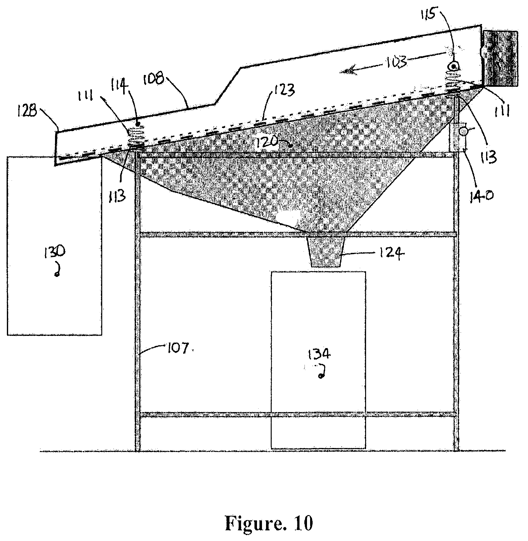
[0070] A preferred apparatus for this purpose is a "knocking", non-blinding filter to produce a filtrate that is substantially reduced in particles above the mesh size that would otherwise be present in the liquid, particularly those particulates that would remain in suspension. The apparatus next described is suitable for treating flowable solids as the feedstock as well as liquids. Such a system can comprise: [0071] a. a resiliently supported frame in turn supporting a durable, permeable filter screen or mesh that is oriented at a flow-supporting downwardly inclined angle, e.g. between 5 and 30, more preferably 5 to 20 degrees from the horizontal for a used lube oil feedstock, [0072] b. an entry region for receiving the feedstock at the upper end of the frame from which the feedstock will flow down the inclined screen to the base end of the frame, [0073] c. a catching container positioned beneath the screen for capturing the filtrate, also referred-to as the "permeate", passing through the screen, [0074] d. an actuator coupled to the resiliently supported frame to apply a force with a component for displacing the frame with a component in a generally horizontal direction, or in a direction aligned with the upward incline of the screen, with a "knocking" action whereby the force applies a rapid onset of acceleration to the screen that assists in dislodging non-penetrating particulate material resting thereon, and, optionally, [0075] e. a return displacement mechanism for causing the filter to thereafter return to its original location.
[0076] The filter media in the used oil application can be a non-disposable steel mesh, preferably a stainless steel mesh with openings on the order of 300 mesh size, e.g., approximately 50 micron opening size, but optionally smaller than 200 microns, more preferably smaller than 100 microns and even more preferably 50 microns but larger than 40 microns. Beneath the mesh is a catching container that is liquid-accommodating when a liquid is being treated. At the lower end of the filter station that supports the frame a receiving container is positioned to collect material that fully transits the length of the filter.
[0077] In the treatment of used lube oil that has previously gone through a settling stage, the length of the screen can be chosen to allow 90% or more--e.g. up to 98-99% of the potential permeate, to penetrate the screen. The non-penetrating particulate component therefore rises in its concentration as it proceeds towards the base of the screen. Near the base end it can virtually form a sludge if allowed to accumulate. The effect of the "knocking" action is to encourage such particulate matter to proceed towards and off the base end of the screen. Conveniently a chute may direct this sludge into a sludge bucket that serves as the receiving container.
[0078] The chute surface, made of a low friction material, is preferable more downwardly inclined than the screen, e.g. 15-30% more. Optionally but preferably at least a portion of the chute narrows from its upper to its lower end. This chute is carried by the resiliently supported frame and experiences the same acceleration cycles as that imposed on the frame and screen by the knocking action.
[0079] The same knocking action serves to dislodge particles in the higher, initial, portion of the screen from blocking screen openings. The knocking action tends to loft the particles back into the fluid flow thereby clearing the screen openings within which they were lodged. Once so lofted the particles are swept, even momentarily, towards the base end of the screen. In this manner virtually all non-pass-through particulates will eventually be conveyed to the base end of the screen.
[0080] The "knocking" effect arises from applying a force to accelerate the screen from underneath particles lodged thereon. For this purpose it is suitable to expose the filter screen to a cyclic motion which includes stages of acceleration and deceleration. These stages are not necessarily symmetrical. In a preferred variant of the invention, the level of acceleration during the "knocking" action is a factor greater than the absolute value of any other acceleration or deceleration stage occurring in the cycle. As a preferred example, this maximum rate of acceleration is more than twice, more preferably over three times the absolute value of any other acceleration or deceleration occurring during an agitation cycle.
[0081] For example, the frame and its accompanying screen, as well as the liquid and particles supported thereon can be exposed to an acceleration of 0.3 g to 5 g, more preferably 1 to 3 g, over at least a short length of its travel, tending to displace the particles that have lodged on the surface of the screen so as to return them into the flow of feedstock descending down the face of the screen.
[0082] The force applied to the frame can be periodic, for example, with a frequency of 1 per 5 seconds to 20 per second. An actuator such as an electrical solenoid can generate the accelerating force. Mechanical linkages connected to a rotating off-center mass that imposes a non-sinusoid motion to the screen can achieve the same effect, including optionally returning the screen to its original position to complete the cycle if the frame for the screen is not otherwise so provided. The return displacement mechanism can be based on a spring or other resilient element to cause the frame and filter screen to return resiliently to their original location. In the latter case the knocking effect can be achieved through a hammer action.
[0083] The described filter of the invention is not necessarily intended to be the final stage in a liquid clarifying process. For example, the filtrate may be subsequently transferred to a centrifuge which simulates enhanced gravity and completes the substantial removal of suspended solid matter and emulsions that can be managed in this manner. And the filtration stage of the invention can be conveniently placed ahead of flash evaporators which remove dissolved liquid components in the feedstock such as water and glycol.
Pretreatment--Removal of Volatiles
[0084] According to one aspect of the invention a gas-liquid exchange interface apparatus for effecting chemical or physical exchanges between a gas and a liquid, or evaporation of volatile from the liquid, comprises a containment for maintaining inner components in a gas-tight, pressure controlled environment. This containment has at least a liquid inlet for introducing the liquid into the containment, a liquid outlet from the containment for evacuating a residual portion of the liquid, and a gas outlet on the containment for introducing or evacuating gases present therein or extracting volatile components evaporated from the liquid.
[0085] Within the containment is a segmented, vertical cascade of support surfaces positioned in the form of a column of segments. The liquid being processed passes progressively downwardly from segment to segment within the column. In each segment a first support surface is positioned to receive the liquid from the liquid inlet onto a central region of the first support surface. From there the liquid will flow radially outward from the central region to and beyond the periphery of the first support surface. This advantageously forms an expanding film as the liquid proceeds outwardly. In so flowing the liquid passes over the top wetted surface of the spinning disc which is open upwardly and uncovered for exposure to release volatiles or carry-out a gas-liquid reaction.
[0086] Each segment is also provided with a peripheral receiving surface and transfer passageway to transfer such liquid leaving the first support surface for deposition onto a second support surface located below. Effectively, the second support surface with its peripheral side surface serves as a kind of catch pan with an encircling rim to serve as the peripheral receiving surface and transfer passageway. Liquid so deposited undergoes inward radial flow over the second support surface towards the central area of the second support surface. A central opening in the central area of the second support surface is positioned to direct the liquid onto the central region of the first support surface of the next consecutive segment.
[0087] Liquid flowing over the second support surface is uncovered for exposure to release volatiles or carry-out a gas-liquid reaction.
[0088] According to a further feature of the invention a liquid distributor means within each segment induces liquid deposited on the central region of the first support surface to flow radially outward from the central region. As well, a liquid gathering means for the second surface draws liquid towards the central region of the second support surface. Additionally, a thermal control source is positioned within at least some of the segments for heating or cooling the liquid passing over the surfaces therein.
Heater/Chiller Features
[0089] The thermal control source can be positioned between the first and second surfaces within the segments for heating or cooling the liquid passing over particularly the second surface. In the heating case the thermal control source can be in the form of suitably insulated electrical resistance heating wires. In either the heating or cooling case the thermal control source can be in the form of tubing carrying a heating or cooling fluid that, by radiation, conduction and/or convection, either heats or cools the second surface and liquid flowing thereon. When positioned between the surfaces some heat transfer can occur with respect to the first surface. Alternately, the thermal control source can be located beneath the second surface. In such case the tubing or electrical wires can in thermal connection with the stationary second support surface or catch pan from below.
[0090] In order to improve the thermal connection between insulated electrical resistance wires and the bottom surface of the catch pan providing the second support surface, the catch pan may be made of aluminum. Further, the electrical insulated electrical wires may be wrapped or enclosed in an aluminum sheet or tube which is tightly crimped shut in order to provide a higher degree of physical contact between the outer insulation of the wires and the aluminum tube. The wires so contained in the crimped aluminum tube may then be readily welded by aluminum welding to an aluminum catch pan with appropriate aluminum filleting to improve thermal conductivity.
[0091] Optionally but preferably temperature sensors are positioned within at least some of the segments that have a thermal control source present. The sensors serve to detect the temperature of the liquid, when present, as it passes through the segment. A controller coupled to a typical temperature sensor is also connected to the source of hot or cold fluid or electricity for the thermal control source and is configured for controlling the rate of delivery of heat transfer by the thermal source to or from the segments so equipped.
[0092] Where conditions require, such as where the liquid being processed is increasing in viscosity as it is being processed, the controller may be arranged to operate by transferring a differing quantity of heat to at least one segment than to another segment in the column. Thus in the example given greater heat can be transferred to one or more segments to reduce the increase in viscosity of the liquid. Such segments in the case of evaporation of volatiles are more likely to be located in the lower portion in the column.
[0093] By sensing the temperature of the liquid in at least two segments of the column while the liquid proceeds through the column the controller can control the rate of transfer of heat to or from the second surfaces of such segments to provide heat flow at different rates to the respective segments. This can be used to accommodate not only an increase in the viscosity of the liquid as it proceeds downwardly through segments of the column but also compensate for the heat effects of exothermal or endothermal reactions that may arise when a gas-liquid reaction is occurring.
Top Surface Liquid Distributing--Spinning
[0094] As an aid to promote the radially outward flow of liquid from the central region to and beyond the periphery of the first support surface, the invention may include a liquid distributor means in the form of a rotatable central shaft having a central axis running through the column. This shaft is connected to the first support surface for rotating the first support surface within the containment and thereby enhancing the radial flow effect. The first support surface in such case can be in the form of a spinable disc with a circumferential perimeter, the discs in the respective segments being mounted on the rotatable central shaft. The "discs" may or may not be slightly conic. The increasing centrifugal force impressed on the liquid as it nears the periphery of the disc tends to overcome increased viscosity which may arise from the loss of volatile fractions. In this spinning disc variant in at least some of the segments of the first support surface can be perforated to allow fluid to pass there through and travel radially outwardly on the underside of such first support surface while being held in place by surface tension. The size of the openings provided by the perforations is dimensioned to support this surface tension effect.
[0095] A similar effect can be achieved by providing or forming the first support surface within such segments with a screen portion that is permeable to permit liquid to pass there through and travel radially outwardly on the underside of such surface. The screen portion can be based upon a wire screen mesh or other woven or fibrous format that will serve as a permeable screen portion and permit fluid to pass there through. The screen should be of a material and configuration that will cause the liquid to cling to and flow over its underside surface through surface tension. In either arrangement the first support surface can be conically shaped and oriented to be opening upwardly so as to bias liquid to pass through the screen or holes for outward travel on the underside of such surface.
Top & Bottom Surface Liquid Distributing--Wiping
[0096] As an alternate variant to the use of spinning discs the liquid distributor means for the first surface can be based upon a wiping blade mounted on a central rotating shaft having a central axis. This shaft serves to rotate the wiping blade and sweep it over the first support surface thereby inducing outward radial flow of the liquid when deposited thereon.
[0097] Such a wiping blade can be employed in a similar manner in respect of the second surface. Such arrangement can be employed whether the first surface is spun or swept at least in respect of some or all of the segments in the column. In such case a wiper blade operates to support or induce inward radial flow--gathering--of the liquid when deposited thereon. When the first surface is being spun or even being wiped the wiping blade for the second surface can be mounted on the same central rotating shaft that provides rotation for the first surface, optionally connected through a speed reducing connector. One suitable connector can incorporate a sun-and-planet gear arrangement to achieve speed reduction. In this manner the upper surface can be spun at a higher speed while the lower surface can be wiped at rates suitable for the respective surfaces.
[0098] The second surface need not be wiped at all. The presence of a liquid distributor means for the second surface includes a configuration where the portions of the second support surface conveying the liquid towards its central region are downwardly inclined and generally conically formed to induce the inward radial flow of the liquid over the second support surface towards the central area of the second support surface under gravity. However, a wiped surface can be less conically inclined.
[0099] The above description applies to effecting both air-liquid chemical reactions and effecting physical processes such as evaporating a volatile from a liquid. The preferred embodiment described below uses the separation of water and glycol from used engine oil as an example. The structure and process of the invention can be used in other cases where a mass transfer occurs at a gas-liquid interface as well as when a volatile component is to be extracted from a liquid.
[0100] The foregoing summarizes the principal features of the invention and some of its optional aspects. The invention may be further understood by the description of the preferred embodiments, in conjunction with the drawings, which now follow.
[0101] Wherever ranges of values are referenced within this specification, sub-ranges therein are intended to be included within the scope of the invention unless otherwise indicated or are incompatible with such other variants. Where characteristics are attributed to one or another variant of the invention, unless otherwise indicated, such characteristics are intended to apply to all other variants of the invention where such characteristics are appropriate or compatible with such other variants.
SUMMARY OF THE FIGURES
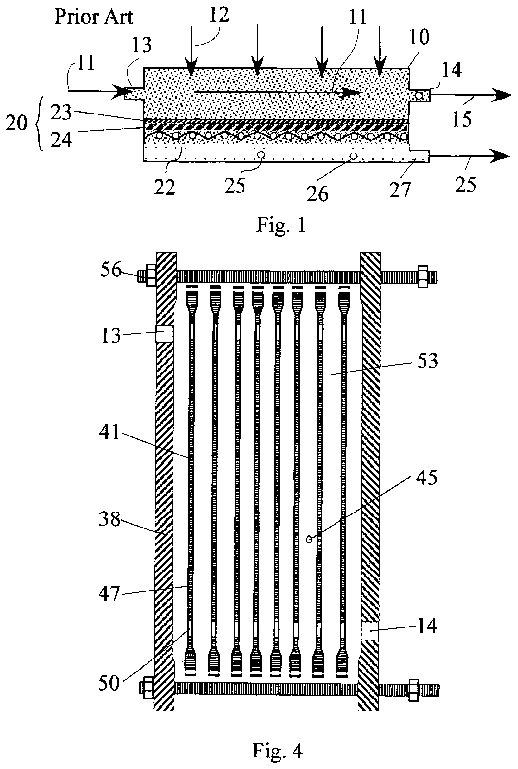
[0102] FIG. 1 is a schematic cross-sectional view through a nano-membrane over which is flowing in cross-flow a feedstock which provides a permeate that passes through the membrane. This figure is intended only as a conceptual introduction and is marked as "Prior Art".
[0103] FIG. 2 is a schematic cross-sectional depiction of the layout of a pressure vessel and external supporting components, indicating the flow of feedstock through multiple chambers divided by separator plates in the context of a used oil recycling operation. Membrane support panels in FIG. 2 are depicted schematically as lines for clarity of depiction.
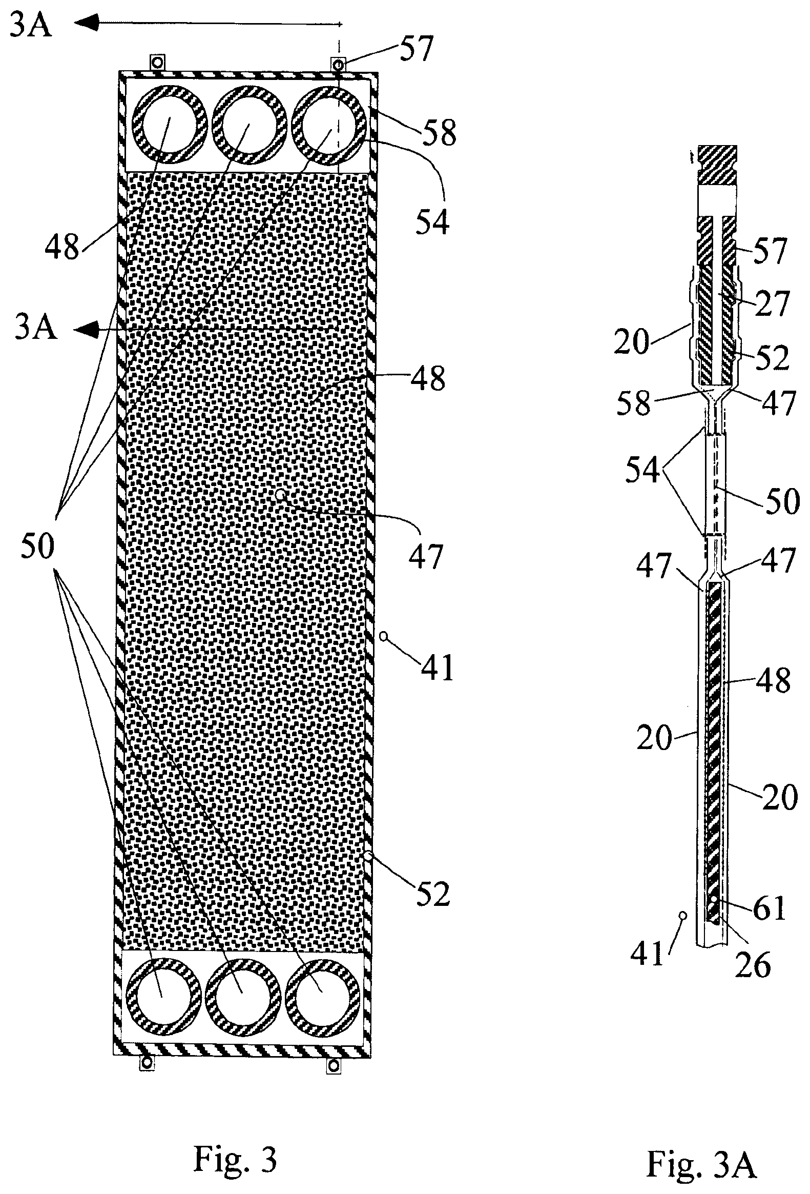
[0104] FIG. 3 is a face view of a basic membrane panel with its individual frame assembly.
[0105] FIG. 3A is a cross-sectional side view through FIG. 3.
[0106] FIG. 4 is a cross-sectional schematic view of a stack of membrane panel assemblies of the type as in FIG. 3 in an expanded state before compression to form a pressure vessel.
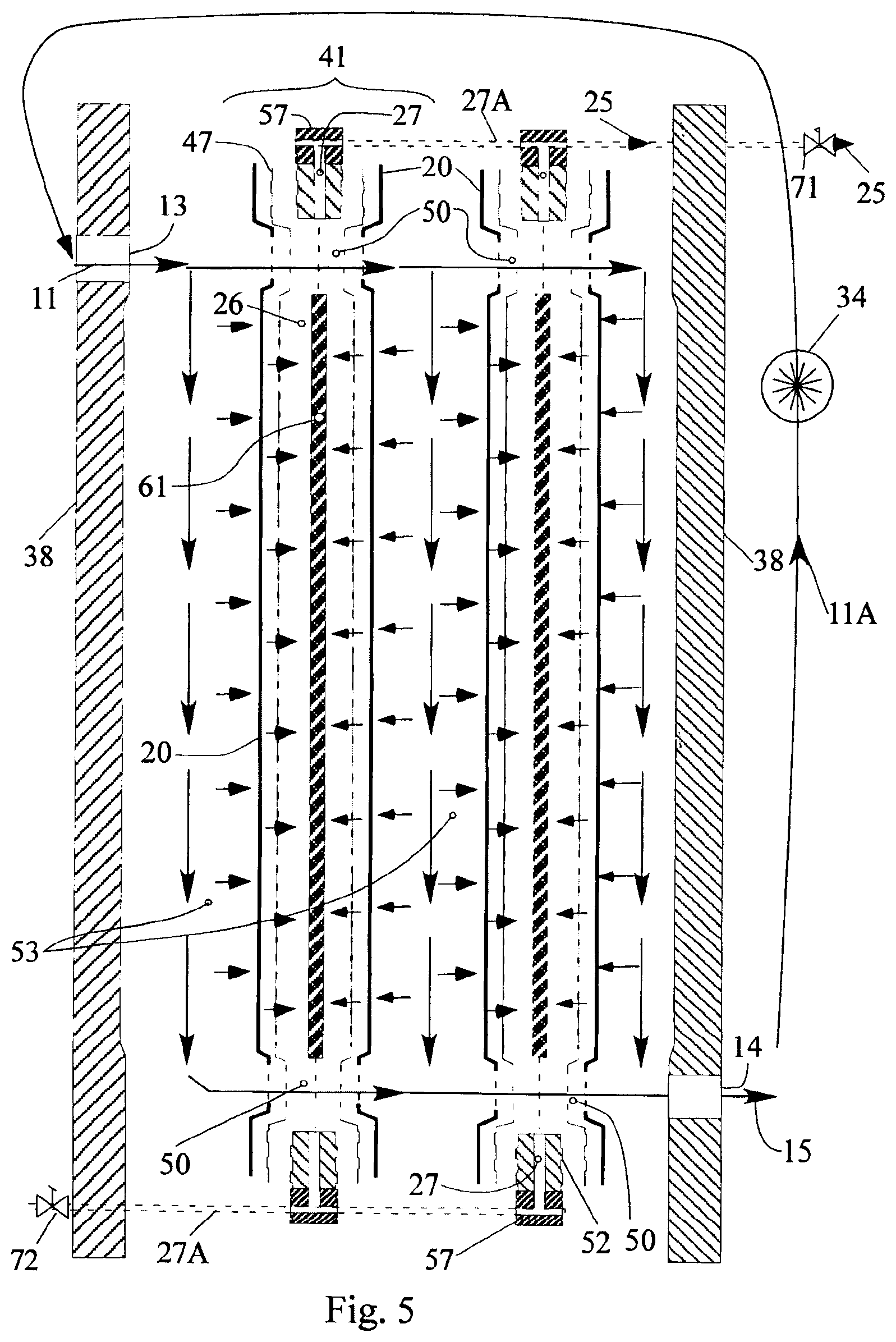
[0107] FIG. 5 shows a further schematic exploded cross-sectional view of a stack of membrane panel assemblies as in FIGS. 3-4 showing the flow of feedstock and permeate. In this figure the feedstock follows a parallel path over the membrane surfaces of two membrane panel assemblies before being recirculated. Details of the permeate manifold and exit passageways are shown in FIG. 8.
[0108] FIG. 6 is a schematic exploded cross-sectional view of a bank of four stacks of membrane panel assemblies as in FIGS. 3-5 with permeate manifold passageways top and bottom.
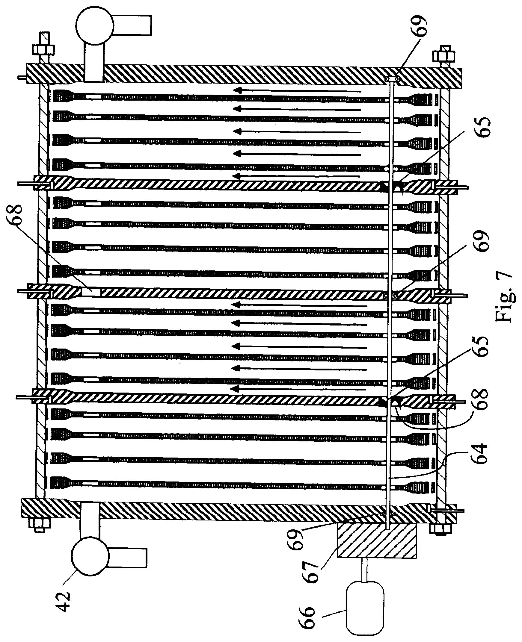
[0109] FIG. 7 is a further view as in FIG. 6 having additionally present pressure boosters in the form of multiple turbine blades mounted on a common shaft within the respective flow-through openings of two of the separator plates.
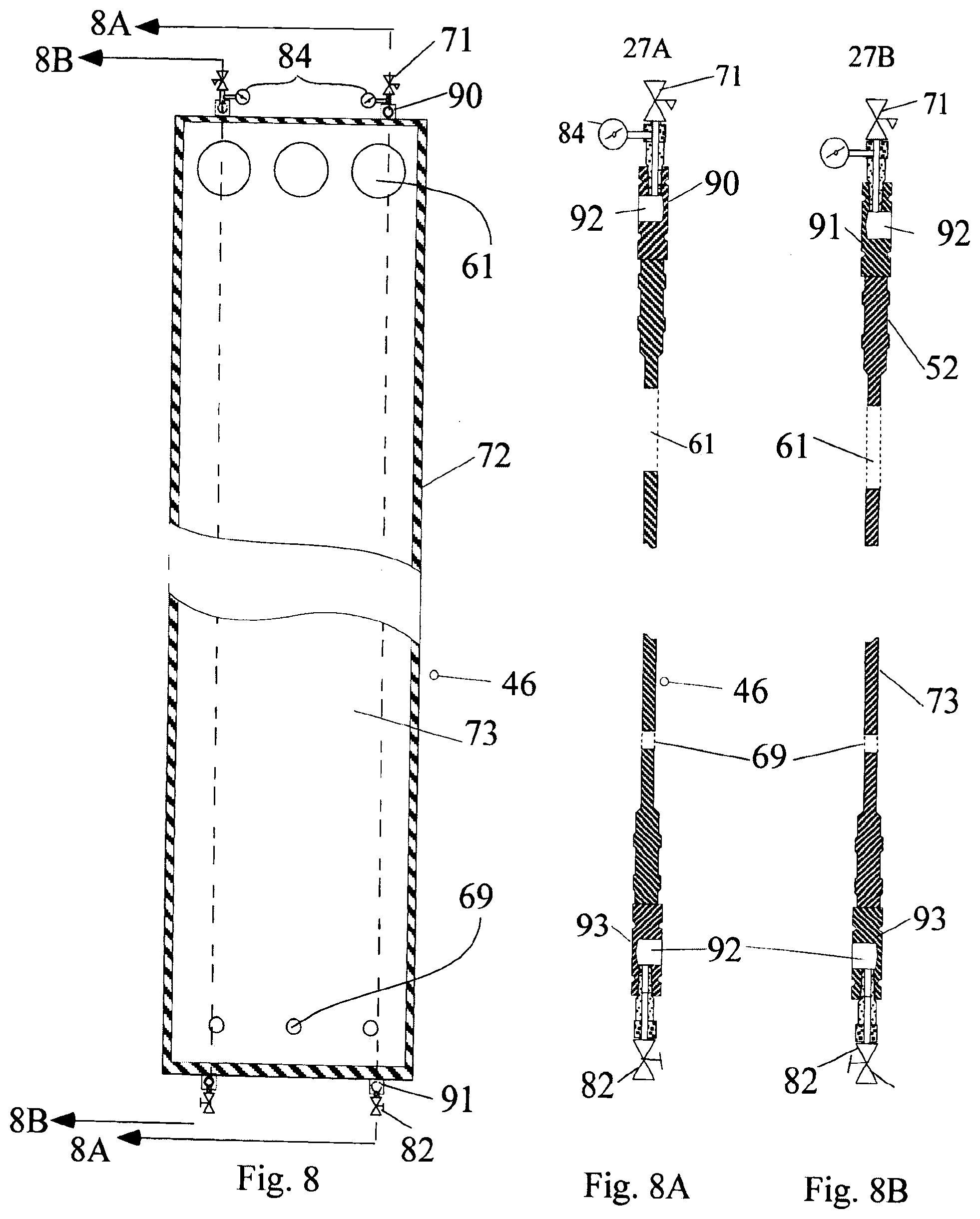
[0110] FIG. 8 is a face view of a separator plate showing the permeate collection structure.
[0111] FIG. 8A is cross-sectional edge view of FIG. 8.
[0112] FIG. 8B is a further cross-sectional view of FIG. 8 showing a mirror image arrangement of the permeate collection structure of FIG. 8.
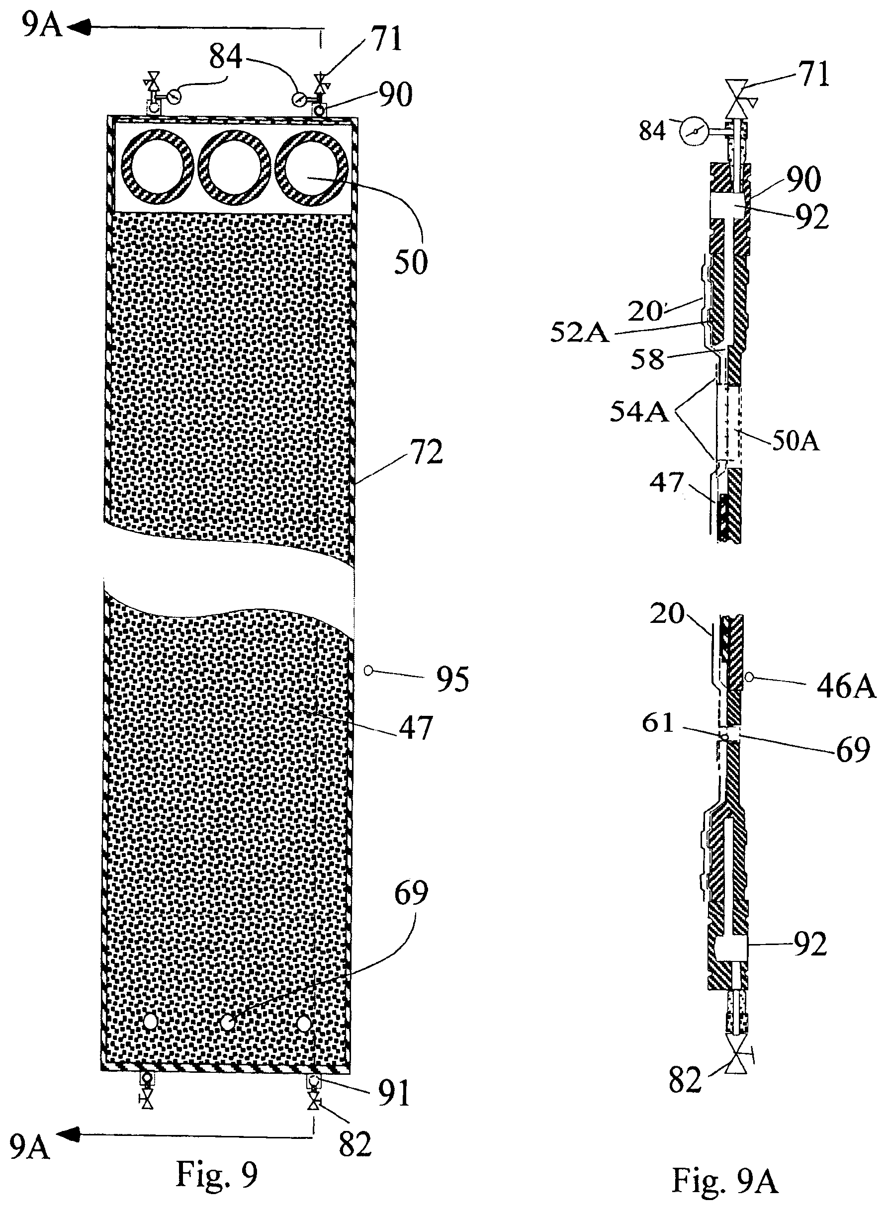
[0113] FIG. 9 is a face view of a modified separator plate having a perforated membrane support panel on one side.
[0114] FIG. 9A is cross-sectional edge view of FIG. 8.
[0115] FIG. 10 depicts a side schematic view of a "knocking" filter for removal of solid and semi-solid grease particles and solids that are larger than the mesh rating of the filter screen from a feedstock.
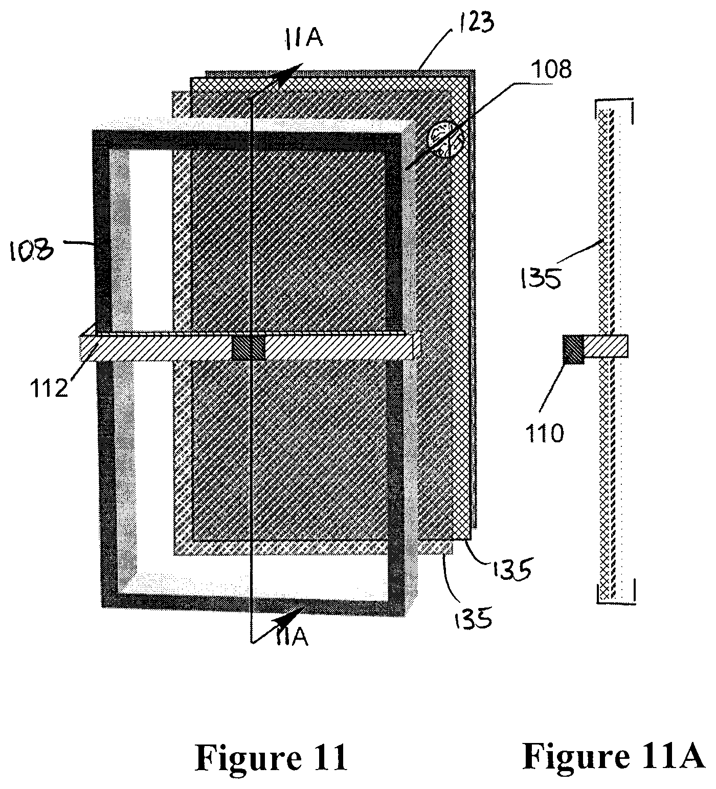
[0116] FIG. 11 is a perspective bottom end view of the resiliently mountable frame and screen portion of the apparatus of FIG. 1 depicting two support grids for supporting the filter screen, the frame also carrying the knocking anvil.
[0117] FIG. 11A is a cross-sectional side view through FIG. 11.
[0118] FIG. 12 is a side view of the apparatus of FIG. 10 showing the actuator mechanism that delivers the knocking action through a hammer and anvil arrangement.
[0119] FIG. 13 is a schematic depiction of a first basic flash evaporator for processing oil using spinning discs showing three segments of a column of segments and external support components.
[0120] FIG. 14 is a schematic variant of FIG. 13 having four segments in column format and two different modes of heating.
[0121] FIG. 15 is a further schematic variant of FIG. 13 showing three segments with three liquid distribution arrangements, spinning and wiping and a combination, and a fourth segment with various heating arrangements.
[0122] FIG. 16 shows a diagrammatic perspective view of an insulated electrical heating wire wrapped in a crimped tube.
[0123] FIG. 17 depicts a spinning disc with perforations to allow liquid to pass there through and travel radially outwardly on the underside surface.
[0124] FIG. 18 depicts a spinning disc with a screen portion that is permeable to permit liquid to pass there through and travel radially outwardly on the underside of such surface.
DESCRIPTION OF THE PREFERRED EMBODIMENTS
[0125] In FIG. 1 a pressure containment vessel 10 contains feedstock 11 flowing under pressure 12 from an inlet 13 to an outlet 14 where it exits as a concentrate 15 depleted of permeate 25. Inside the vessel 10 a membrane 20 is carried by a permeable, e.g. perforated, support 22 shown schematically as wire mesh 22 but in a preferred variant is a perforated metal panel. The membrane 20 has a skin 23 and a spongy sub-layer 24. Permeate 25 that has passed through the membrane 20 into a permeate collection cavity 26 exits through a permeate outlet 27. The membrane 20 may be cast onto a supporting scrim or carrier sheet (not shown) to give it improved dimensional stability.
[0126] The cavity 26 may contain a permeable cavity propping structure 61 (shown in FIG. 5) to minimize deflection of the support 22. This can optionally be in the form of a further wire mesh that occupies the cavity 26 and supports the membrane support 22.
[0127] Membranes suitable for use with the invention in a used lubricating oil application are believed to be available from:
[0128] Koch Membrane Systems, Inc.
850 Main Street
Wilmington, Mass.
[0129] 01887-3388
USA
[0130] EMD Millipore Corporation
290 Concord Road
Billerica
Massachusetts 01821
United States of America
[0131] U.S. Pat. No. 4,818,088 also describes a nano-membrane for use with aliphatic hydrocarbon liquids suitable for incorporation into the invention described herein in such application.
Filtration System Layout
[0132] In FIG. 2 a holding tank 30 contains a supply of appropriately pre-treated feedstock 11. A heater 29 adjusts the temperature of the feedstock 11 in the tank 30 to preferably around 90.degree. C., e.g. 80.degree.-110.degree. C. in the lube oil application. Feedstock 11 is then delivered by a feedstock delivery and pressurizing pump 32 to a loop system 33 that extends through a containment vessel 35 bounded by end plates 38. The feedstock 11 within the loop system 33 is circulated and kept pressurized by a circulating pump 34 until the desired amount of permeate has been extracted.
[0133] Feedstock 11 enters the containment vessel 35 bounded by end plates 38 at an inlet 13. This inlet 13 is fitted with an inlet diffuser 42 to distribute the flow amongst the membrane panel assemblies 41 within the containment vessel 35. Initially the hot feedstock 11 heats the apparatus while being circulated at low speed. Then the circulation rate and pressure within the loop 33 can be increased to process the feedstock 11 more rapidly.
[0134] The containment vessel 35 includes a series of individual membrane panel assemblies 41 (depicted schematically as lines 41 in FIG. 2) around which the feedstock 11 passes in a serpentine flow path 37. In this schematic figure, four stacks 45 of membrane panel assemblies 41 are depicted as being exposed to liquid flow. Each stack 45 is separated from adjacent stacks 45 by a pressure-supporting separator plate 46. Aligned with the passageways 50 (in FIG. 3) in the membrane panel assemblies 41 are flow-through openings 68 (in FIG. 3A) in the separator plates 46 allowing the feedstock 11 to pass from stack 45 to stack 45.
[0135] At the outlet collector 42 partially concentrated feedstock 11A exits from containment 35 to flow around the loop 33. Eventually a loop outlet pump 43 extracts more fully depleted concentrate 15 from the loop 33 through a back-pressure control valve 43 for delivery to a processed-concentrate holding tank 44.
[0136] As shown in FIG. 3 a membrane panel assembly 41 has two perforated panels 47 for supporting respective membranes 20 (not shown in this figure) on their outside surfaces. The perforations 48 optionally terminate before reaching the ends of the assembly 41. Circular passageways 50, shown as an exemplary three at each end, penetrate the two panels 47 near their respective ends where the panels 47 are preferentially pressed into contact with each other. Clamping circular sealing rings 54 bound the passageways 50 ensuring the integrity of the collection cavity 26 (in FIG. 3A) between the two panels 47. Permeate conduits 58 along the panel perimeter at the collapsed ends allow permeate 25 to flow from the collection cavity 26 along the periphery of the panel-pair 47 (in FIG. 3A) to exit through permeate outlets 27 at one or more of the ends of the panels 47 and into permeate manifold 27A.
[0137] As best shown in FIG. 3A, pinched between the two panels 47 along their outer peripheries is a stiffening frame 52, preferably of welded steel and of rectangular cross-section. This frame 52 stiffens the panels 47. The frame 52 also acts as a spacer between panels 47 and provides part of the wall of the containment vessel 35. The outer edges of a membrane 20 (not shown in FIG. 3 but shown as a line in FIG. 3A) on each panel's 47 outer boundary is also pinched between panels 47 and frames 52 under the compressive force of exterior bolts 56 when everything is assembled. Such bolts 56 (in FIG. 4) extend between the end plates 38 around the periphery of the containment vessel 35.
[0138] In FIG. 3A the membrane 20 is pinched around the passageway 50 by the sealing rings 54. The inside cavity 26 receives permeate from the feedstock 11. This pinching seal may be enhanced by the use of a gasket (not shown) which will not only isolate the inner permeate collection cavity 26 from the feedstock flow 11 but will also help pinch the membrane 20 in place under the sealing ring 54.
[0139] Permeate conduits 58 can run adjacent to the inner portion of the frame 52 to carry permeate 25 to the ends of the membrane panel assemblies 41.
[0140] In FIG. 4 a single stack 45 of individual membrane panel assemblies 41 is located within the containment of the pair of end plates 38 held together by bolts 56. Collectively, these end plates 38 and the peripheries of the membrane panel assemblies 41 define the containment vessel 35.
[0141] Individual panel assemblies 41 have passageway openings 50, also shown in plan view in FIG. 3, to allow parallel flow of feedstock 11 to be distributed in the spaces or gaps 53 between panel assemblies 41. These gaps 53 provide a "headspace" for feedstock over the membrane 20. Conveniently, in FIGS. 4-7 these passageway openings 50 are shown as aligned openings in the panel assemblies 41 to accommodate a feature described further below.
[0142] The height of the headspace provided by the gaps 53 has an important effect on the operation of the system. As this headspace 53 gets narrower, the pressure drop along a given length of membrane 20 will increase. If higher feedstock pressures are used, then, for a given gap height 53, the feedstock 11 flow rate will be higher. This flow rate will help "scrub" non-passing feedstock matter off the surface of the membrane 20, reducing membrane blockage. At the same time, such over-pressure can affect "concentration polarization" on the surface of the membrane. This has the consequence of thickening the boundary layer of fluid flow over the membrane, which will reduce permeate flow. For this reason trans-membrane pressure should not be allowed to become excessive.
[0143] FIG. 5 shows the path of flow of feedstock 11 and permeate 25 in between and around a pair of panel assemblies 41. Also as shown in FIG. 5, the cavity 26 contains a permeable cavity propping structure 61 to minimize deflection of the panel 47.
[0144] In FIG. 5 permeate 25 is shown as flowing through the permeate outlet 27 penetrating the frame 52 at the upper end of the individual panel assemblies 41. The permeate 25 is gathered through tabs 57 into a manifold 27A of tubes for eventual further disposal as shown in FIG. 8.
[0145] Permeate 25 exiting from each stack 45 of panels eventually passes through a back-pressure control valve 71 that is adjusted to maintain the pressure drop across the membrane 20 in the associated stack 45 of panel assemblies 41.
Serpentine Flow
[0146] In FIG. 6 multiple sets or "stacks" 45 of panel assemblies 41 are assembled to permit direction-reversing flow of feedstock 11 through consecutive stacks 45. As in FIGS. 4-6, end plates 38 of the containment vessel 35 are shown but, for convenience of depiction, the membrane panel assemblies 41 are shown as being separated before the bolts 56 apply a compacting force. In actual use, the bolts 56 are tightened with the frames 52 dimensioned at the boundaries of the panel assemblies 41 to allow the bolts 56 to draw the panel assembly ends together. This action also secures the membrane 20 in position on the pair of associated panel assemblies 41, pinching these components together while providing the spacing between panels that establishes the inter-panel gap and headspace 53.
[0147] In FIG. 6 separator plates 46 are present between consecutive stacks 45 of membrane panel assemblies 41. As shown in FIG. 8 the perimeter 72 of a separator plate 46 is shaped and dimensioned similarly to that of the membrane panel support assemblies 41 to ensure the integrity of the pressure containment volume 35. Within this perimeter 72 the face surfaces 73 of the separator plates 46, as with the end plates 35, may be slightly inwardly displaced to provide headspace 53 for the membrane 20 on adjacent panel assemblies 41.
Pressure Boost
[0148] In FIG. 7 the flow-through openings 68 in the separator plates 46 are penetrated by a rotating shaft 64 passing there through. Mounted on such shaft 64 in the flow-through opening 68 in every second separator plate 46 is a pressure booster 65 in the form of a fluid impeller. The seal 69 where the shaft 64 pierces the intermediate separator plate 46 is intended to be pressure-tight.
[0149] The shaft 64 is turned through a transmission 67 by an external electric motor 66. Thus, as the feedstock 11 passes from stack 45 to stack 45 in the bank of stacks, its pressure is boosted, making-up for the pressure loss incurred by flowing in a cross-flow over the surface of the membranes 20. The motor 66 may be a variable speed motor to control the amount of the pressure boost. Although a common shaft 64 is shown as actuating the pressure boosters 65, each pressure booster 65 could have its own individual electric motor.
[0150] As depicted in some of the Figures so far for the individual membrane support panel assemblies 41 and separator plates 46, reference has been made to an opening, (in the form of a passageway 50 (in FIG. 4) or flow-through opening 68 (in FIG. 7)), respectively formed therein near their ends. In fact multiple such openings 50, 68 may be present side by side to support a high flow rate through such openings 50, 68. Singly or collectively such openings qualify as a passageway 50 or a flow-through opening 68. In the case of multiple openings, multiple pressure boosters 65 should occupy the openings to maintain the pressure boost.
[0151] In FIG. 7 the multiple impellers 65 are positioned at the bottom of the first and third, and in expanded variants, in all odd numbered separator plates 46. The second separator plate and all even numbered separator plates 46 each have a penetration with a pressure-tight bearing 69 for the shaft 64, or multiple shafts 64 in the case of multiple openings 50, 68.
[0152] In configurations where the pressure drop within the flow of feedstock 11 is significant, e.g. the length of cross-flow along the membranes 20 in one or more stacks 45 is considerably extended or the feedstock 11 is viscous as in the case of heavy oil, a second set of pressure boosters 65 may be installed at the other end of the separator plate 46. Thus further multiple impellers 65 may be positioned at the top of the second, fourth and all even numbered separator plates 46. In this separate array of pressure boosters 65, all odd numbered separator plates 46 would have appropriately aligned pressure-tight bearings 69. This second shaft, or set of shafts, would have its own drive mechanism 66, 67 and speed control. For such long panels, the unit could beneficially be positioned on its side.
Trans-Membrane Pressure Control
[0153] To dispose of permeate 25 each stack 45 is provided with a first permeate outlet manifold 27A (in FIG. 5) that delivers permeate 25 to a proximate separator plate 46. As shown in FIG. 8 such plates have aligned permeate reception tabs 90, 91 corresponding to tabs 57 in FIGS. 3 and 5 and blind recesses 92 (in FIGS. 8A and 8B) that receive the permeate manifold 27A and divert permeate 25 out of the pressure containment vessel 35 through permeate pressure control valves 71. Thereafter permeate 25 flows at near atmospheric pressure for accumulation outside the pressure vessel 10. Only one permeate reception tab 90 is needed for a separator plate 46 but by providing two such tabs 90, 91 as mirror arrangements the separator plates 46 can be more versatile, avoiding the need to have "left" and "right" plates 46 on assembly. Each plate 46 can thereby receive permeate 25 from the stacks 45 on both or either side.
[0154] By providing each back-pressure valve 71 (in FIGS. 8, 8A, and 8B) with a pressure sensor 84 and individual valve controller (not shown), the controller can receive signals from the sensor 84 and deliver signals to control the valve 71. This allows different back pressures to be established for various stacks 45 through which the feedstock 11 is passing at progressively decreasing feedstock pressures 12 if there is no inter-stack pressure boost. The pressure of the feedstock 11 around each stack 45 can be interpolated by knowing the inlet 13 and outlet 14 pressures in order set back-pressure valves 71 to create the preferred trans-membrane pressure differential.
[0155] Drain tabs 93 (in FIGS. 8, 8A, and 8B) at the other end of the separator plate 46 can be fitted with manual valves 82 for use when permeate 25 is to be drained from the panel assemblies 41 on disassembly.
[0156] The permeate back-pressure control system as described is suitable for providing a preferred trans-membrane pressure when feedstock 11 is delivered to the containment vessel inlet 13 at a significantly elevated inlet pressure level 12. The consecutive pressure-boosting provisions for the individual consecutive stacks 45 described previously as part of this invention can obviate the need to deliver feedstock 11 to the container inlet 13 at an elevated inlet pressure 12. Nevertheless, in order to maintain trans-membrane pressures at reasonable values in either such cases, the permeate back-pressure control system as described can be used to set or fine-tune the trans-membrane pressure for individual stacks by adjusting the pressure of the associated membrane collection cavities 26.
Hybrid Separator Plate
[0157] The separator plate 46 need not be an independent component. FIGS. 9, 9A show a hybrid separator plate 46A and single membrane support panel 47. A perforated metal panel 47 is mounted on a modified separator plate 46A. Permeate 25 flows directly to the blind recess 92 through the permeate conduit pathway 58 in the modified separator plate 46A. The hole 50 in panel 47 is ringed by a modified sealing ring 54A that engages flow-through opening 68 in the modified separator plate 46A. This modified ring 54A and a shaped portion 52A of the plate 46A configured as a frame 52 position the membrane 20 in place. The modified separator plate 46A has a perimeter on one side, shaft penetration 61 and pressure seal 69 as before.
[0158] In this variant the lightly built perforated metal panel 47 is supported and stiffened by the pressure-sustaining modified separation plate 46A providing effectively a stiffened membrane panel support assembly 41 with a separator plate 46 embedded therein. If desired the modified separator plate 46A may also be perforated although this may prove costly for a thickened plate.
Number of Panels in Each Stack
[0159] As the feedstock 11 passes through a series of stacks 45, its pressure will be progressively reduced. At the same time, a portion of its volume will be carried-away in the permeate 25 that passes through the membranes 20. This loss of volume, after a number of stacks 45 have been passed-through will reduce the rate of feedstock 11 flow across membrane 20 surfaces.
[0160] To maintain the cross-flow fluid velocity at a desired level, the number of membrane support panels 41 in later stacks 45 in the series can be reduced. Thus, for example, where the initial stack count includes twenty membrane panels, then after, say, ten stacks in the series, the twenty first stack may have its panel count reduced to nineteen. This process can be repeated if the number of stacks in the series is extended substantially. The values in the example given will vary with the viscosity of the feedstock 11, the length of panel assemblies 41, the number of stacks in the system and other parameters.
Mounting of Membrane Support Panels
[0161] When finally assembled, the membrane support panels 41 and separator plates 46 which provide a portion of the boundaries of the pressure containment vessel 35 are held rigidly in place by the compressive force of the end plates 38 that are drawn towards each other by tightening the peripheral arrangement of bolts 56. This compressive force is high and the integrity of the arrangement once assembled is secure.
[0162] During initial assembly, temporary rails may be provided between the two end plates 38 to align individual panels being positioned there between in respect of their vertical position. Spacers located alongside side bolts 56 can ensure proper alignment in the horizontal direction.
[0163] In most applications where a pure base stock is required for producing fresh lubricating oil, the permeate 25 may be subject to a final treatment by passing it through a commercially available Polishing Unit that relies on activated clays. It is not represented that the output from the filtration system as describe is absolutely ready for use as a base stock for preparing lubricating oil.
[0164] While the above description has focused on an apparatus for recovering base lube oil stock from used lubricating oil, the invention and the apparatus hereinafter claimed is equally applicable to any suitable liquid filtration process that relies on a membrane as the filtering medium.
Knocking Filter
[0165] In FIG. 10 a supported screen frame 108 is carried by resilient supports 111 such as rubber posts or coiled springs that are seated on a stationary support structure 107. The resilient supports 111 serve as a return displacement mechanism for causing the assembly of supported components to thereafter return to its original location. While the resilient supports 111 described hereafter carry the weight of the supported assembly, an arrangement based upon sliding rails to carry the weight of the assembly and separate springs to restore the assembly to its starting location would perform equivalently, and would be understood to also constitute a resilient support.
[0166] The resilient supports 111 may be in tension or compression but their base ends 113 are anchored to the stationary support structure 107. The opposite ends 114 of the supports 111 are optionally connected to the screen frame 108 through couplings 115 that allow rotation. The function of these resilient supports 111 is to allow the screen frame 108 and its contents to be displaced as part of the "knocking" action, and then return the screen frame 108 with its contents to substantially return to its original position prior to a subsequent cycle.
[0167] In FIG. 11 the screen frame 108, preferably made of powder painted steel angle iron or channel, supports and carries multiple layers of steel wire support grids 134 (two only support grids only are shown in FIGS. 11 and 11A). These grids may typically have respective square openings of 2 inches, 1/2 inch, and 30 mesh or 0.0232 inches. The filtration screen 123 rests upon the finest mesh support grid 134.
[0168] The resilient supports 111, screen frame 108 and inner grids 134 are positioned to orient the screen 123 at a flow-supporting upwardly inclined angle, e.g. between 5 and 20 degrees to the horizontal for a lube oil feedstock. This angle is preferably adjustable by a tilt control actuator 140 to control residence time for the feedstock on the screen 123.
[0169] In FIG. 12 a supply source feed pump 100 delivers feedstock 103 through the feed pipe 102 to a diffuser 106 for deposit onto the upper end of the screen frame 108. The feedstock 103 then flows under gravity down the inclined filter screen 123, towards the base end 128 of the screen frame 108. In the treatment of used lube oil that has previously gone through a settling stage, the length of the screen 123 can be chosen to allow 90% or more--up to 98-99%--of the potential permeate to penetrate the screen 123. Appropriate dimensions for the screen 123 that have been found effective are approximately 1 m in length and 1/2 m in width. Beneath the screen 123 a catching surface 120 gathers permeate for delivery through drain 124 to a permeate catching container 134 for capturing the permeate passing through the screen 123. A permeate recovery pump 139 empties the permeate catching container 134.
[0170] Upon reaching the base end 128 of the screen frame 108 the residual portion of the feedstock 103 passes off of the filter screen 123 through conduit 140 into a sludge tank 130. A sludge pump 131 empties the sludge tank 130 periodically.
[0171] As seen in FIGS. 11, 11A and 12 a yoke 112 spanning between the two lateral sides of the screen frame 123 has an anvil 110 positioned centrally there between. The yoke 112 and anvil 110, respectively, are preferably approximately mounted along the 2 vertical planes of reference passing through the center of mass of the components carried by the resilient supports 111. The yoke 112 is therefore approximately aligned transversely with the vertical plane crossing the width of the supported assembly of components, and the anvil 110 is aligned with the vertical plane that includes the longitudinal centerline of the screen frame 108.
[0172] FIG. 12 shows the detail of the actuation system that creates the "knocking" effect by applying a rapid onset of acceleration to the assembly of supported components. This is the action that assists in dislodging non-penetrating particulate material resting on the screen 123.
[0173] A motor (not shown) turns a plate 117 with an off-centered pin 119 that serves as a crank handle. Linked to the crank handle pin 119 is a connecting rod 116 and short link 116A. The connecting rod 116 may optionally be constrained by linear bearings (not shown). At the end of the connecting rod 116 is a hooked end 114 which serves as a hammer 114 for striking the anvil 110. The connecting rod 116, link 116A and hooked end 114 are preferably dimensioned and positioned so as to cause the hammer 114 to strike the anvil 110 when the crank handle pin 119 is moving fastest in its rotary cycle. The link 116A effectively creates "slop" in the connecting rod 116, link 116A connection to the crank handle pin 119. Once set in motion by the fastest pulling effect from the crank handle pin 119, these links and the hammer can continue in motion for a short moment thereafter, long enough for the hammer 114 to strike the anvil 110, while the erstwhile pulling effect from the crank handle pin 119 declines due to its rotary motion.
[0174] This "slop" is also present when the hammer 114 is forced to retire from the anvil-hitting location. The hammer 114 may even bounce-back slightly on hitting the anvil 110. Effectively, the hammer 114 is thrown intermittently in both directions. The related components are dimensioned and positioned to provide the regular "knocking" effect for the system.
[0175] Blows are preferably struck by the hammer 114 to the anvil 110 at intervals sufficient to ensure that the supported assembly of components has largely come to rest, although this is not essential. The direction of the blow struck by the hammer 114 need not be precise. The anvil 110 and supported assembly of components will move in the direction constrained by the resilient supports 111.
[0176] The actuation system of FIG. 12 may be replaced by an electrically driven solenoid mounted on the stationary support structure 107 of the assembly. Electrical impulses supplied to the solenoid from an electrical current generator are preferably synchronized to cause the solenoid shaft to strike anvil 110 once it comes substantially to its rest position. The restoring force based upon the spring constant of the resilient supports 111 and the damping factor inherent in such supports 111 can be selected to allow the solenoid to strike the anvil 110 as often as the frame 108 comes to rest.
Vapour Removal
[0177] In FIG. 13 containment 210 is in the form of flanged pressure tank 210 of a size suitable to accommodate the required number of segments 220 for the system flow rate.
[0178] This containment 210 has at least a liquid inlet 211 for introducing liquid 212 into the containment 210, a liquid outlet 273 for evacuating a residual portion 212A of the liquid 212, and a gas outlet 215 on the containment 210 for introducing or evacuating gases 216 present therein or extracting volatile components 216 evaporated from the liquid 212. A vacuum line 260 connected to the gas and vapor outlet 215 evacuates the pressure tank 210 gaseous contents to a condenser 254.
[0179] The containment 210 is preferably wrapped with an external heater (not shown) and thermal insulation (not shown) to maintain internal heat and prevent condensation on the inside surfaces.
[0180] If a sweeping gas were desired then CO.sub.2, N.sub.2 or other appropriate gas 270 or mixed gas stream could be introduced through gas inlet 219 to assist in sweeping out gases 216 and vapors through gas outlet 215. Entrained vapors may be collected in an externally located condenser 254 for removal as liquid through the positive displacement--PD pump 255 that is isolated from the vacuum environment by a normally closed--NC solenoid vapor valve 256. The sweep gas 270 may be vented or reused if of sufficient purity.
[0181] Within the containment 210 is a segmented, vertical cascade of support surfaces 221, 222 positioned in the form of a column 219 of segments 220. FIG. 13 shows two segments. FIG. 214 shows 4 segments of differing types. Any number of segments 220 can be used. A convenient number has been found to be 10-12.
[0182] As shown in FIG. 13, in the first segment 220 the liquid 212 being treated is poured constantly onto the central region 223 of the first support surface 221 by a supply tube 272 connected to the liquid inlet 211 of the containment 210 vessel. Metering valves (not shown) control the rate of flow of the liquid 212. The liquid 212 being processed passes progressively downwardly from segments to segment within the column 219. In each subsequent segment 220 the first support surface 221 is positioned to receive the liquid 212 from the prior segment 220.
[0183] Once deposited on the upper support surface 221 of a segment 220 the liquid 212 flows radially outward from the central region 223 to and beyond the periphery of the first support surface 221. This advantageously forms an expanding film as the liquid 212 proceeds outwardly.
[0184] Each segment 220 is also provided with a peripheral receiving surface 224 and transfer passageway 225 to transfer such liquid 212 leaving the first support surface 221 for deposition onto a second support surface 222 located below. The peripheral receiving surface 224 can be an internal cylinder 224 within the containment 210 that holds the second support surfaces 222 in place. Or it can be a rim on a second support surface 222 within each segment 220 to form a kind of stationary catch pan 226.
[0185] Liquid 212 deposited on the second support surface 222 undergoes inward radial flow towards the central area 227 of the second support surface 222. In one variant the liquid 212 is gathered by its conical shape or its flow may be caused by or assisted by assisted by a liquid gathering means 232 shown as an appropriately angled wiper blade 232. A central opening 230 in the central area 227 of the second support surface 222 is positioned to direct the liquid 212 onto the central region 223 of the first support surface 221 of the next consecutive segment 220.
[0186] In FIG. 13 the liquid distributor 231 that induces liquid 212 deposited on the central region 223 of the first support surface 221 to flow radially outward from the central region 223 is a spinning disc 245. As well, the liquid gathering means 232 for the second surface that draws liquid 212 towards the central area 227 of the second support surface 222 is its conical slope in one sample segment assisted by a wiper blade 232 as shown in another segment 220A.
Heater/Chiller Features
[0187] Additionally, a thermal control source 233 is positioned within at least some of the segments 220 for heating or cooling the liquid 212 passing over the second surface. In FIG. 13 electrical heating wires 234 lie on the underside of the catch pan 226. The thermal control source 233 can either heat or chill liquid 212 flowing over the second surface.
[0188] As shown in FIGS. 14 and 15 the thermal control source 233 can be positioned between the first and second surfaces within the segments 220 for heating or cooling the liquid 212 passing over the second surface 222. In the heating case the thermal control source 233 can be in the form of suitably insulated electrical resistance heating wires 234. In either the heating or cooling case the thermal control source 233 can be in the form of tubing 235 carrying a heating or cooling fluid 236 that, by radiation, conduction and/or convection, either heats or cools the second surface 222 and liquid 212 flowing thereon. Alternately, the thermal control source 233 can be located beneath the second surface 222 on its underside. In such case the tubing 235 or electrical wires 234 can in thermal connection with the second support surface 222 or catch pan 226 from below.
[0189] Either or both surfaces 221, 222 in a segment 220 may be heated or cooled as described above if they are both stationary. FIG. 15 shows dual stationary surfaces. Not every surface or segment 220 need be heated or cooled. But a sufficient number should be provided with a heat transfer to maintain an optimal reaction without risking denaturing of the liquid 212 by over-heating or quenching the reaction with over-cooling.
[0190] When heating for the catch pans 226 is provided by electrically insulated electrical resistance wires 234 thermally coupled to the underside surfaces of the catch pans 226, care should be taken that the wires 234 that are nowhere exposed to the vacuum as electrical leakage may occur through a vacuum. Electrical connections may be insulated by high temperature epoxy adhesive such as that provided by Cotronics Corp of Brooklyn, N.Y., USA 11232:
https://www.cotronics.com/vo/cotr/ea_ultratemp.htm Alternately such connections may be sealed in air-containing sleeves.
[0191] In order to improve the thermal connection between insulated electrical resistance wires 234 and the bottom surface of the catch pan 226 providing the second support surface 222, the catch pan 226 may be made of aluminum. Further, as shown in FIG. 16, the insulated electrical wires 234 (high temperature insulation) may be wrapped or enclosed in an aluminum sheet or tube 240 which is tightly crimped shut in order to provide a higher degree of physical contact between the outer insulation of the wires 234 and the aluminum tube 240. The wires 234 so contained in the crimped aluminum tube 240 may then be readily welded by aluminum welding to an aluminum catch pan 226 with appropriate aluminum filleting to improve thermal conductivity.
[0192] Optionally but preferably temperature sensors 241 are positioned within at least some of the segments 220 that have a thermal control source 233 present. The sensors 241 serve to detect the temperature of the liquid 212, when present, as it passes through the segment 220. A temperature controller 242 coupled to a typical temperature sensor 241 is also connected to the source of hot or cold fluid 236 or electricity for the thermal control source 233 and is configured for controlling the rate of delivery of heat transfer by the thermal source to or from the segments 220 so equipped.
[0193] Where conditions require, such as where the liquid 212 being processed is increasing in viscosity as it is being processed, the temperature controller 242 may be arranged to operate by transferring a differing quantity of heat to at least one segment 220 than to another segment 220 in the column 219. Thus in the example given greater heat can be transferred to one or more segments 220 to reduce an increase in viscosity of the liquid 212. Such segments 220 in the case of evaporation of volatiles are more likely to be located in the lower portion in the column 219. This controller 242 can be also be used to accommodate the heat effects of exothermal or endothermal reactions that may arise when a gas-liquid reaction is occurring.
Top Surface Liquid Distributing--Spinning
[0194] In FIG. 13 a rotatable central shaft 243 having a central axis 214 runs through the column 219. This shaft 243 can be square for ease of engagement and is connected to the first support surface 221 for rotating the first support surface 221 within the containment 210. This will enhance the radial flow effect. The first support surface 221 in such case can be in the form of a spinable disc 245 with a circumferential perimeter, the discs 245 in the respective segments 220 being mounted on the same rotatable central shaft 243.
[0195] As shown in FIG. 14 an external motor 256 or internal magnetic drive mechanism (not shown) for shaft 243 supporting the discs 245 can turn the discs 245 at a convenient 120 rpm as the most advantageous speed for typical fluid viscosities. Use of a magnetic drive is preferable as this will remove the need for having inefficient and leaky shaft seals. When an external motor 256 is driving the shaft 243 a "pump" type gas-tight seal 273 can be employed where the shaft 243 enters the containment 210 vessel.
[0196] As shown in FIG. 17 in this spinning disc variant at least some of the segments 220 of the first support surface 221 can be provided with perforations 246 to allow liquid 212 to pass there through and travel radially outwardly on the underside of such first support surface 221 while being held in place by surface tension. The size of the openings provided by the perforations 246 is dimensioned to support this surface tension effect.
[0197] A similar effect can be achieved by providing or forming the first support surface 221 within such segments 220 with a screen portion 251, FIG. 18, that is permeable to permit liquid 212 to pass there through and travel radially outwardly on the underside of such surface. The screen portion 251 can be based upon a wire screen mesh or other woven or fibrous format that will serve as a permeable screen portion 251 and permit liquid 212 to pass there through. The screen 251 should be of a material and configuration that will cause the liquid 212 to cling to and flow over its underside surface through surface tension. In either arrangement the first support surface 221 can be conically shaped and oriented to be opening upwardly, or downward as shown in FIG. 15 so as to bias liquid 212 to pass through the screen 251 or holes 246 for outward travel on the underside of such surface.
Top & Bottom Surface Liquid Distributing--Wiping
[0198] As an alternate variant to the use of spinning discs the liquid distributor 231 for the first surface can be, as shown in FIG. 13, based upon a rotating wiping blade 252 mounted on a central rotating shaft 243 having a central axis 244. This shaft 243 serves to rotate the wiping blade 252 and sweep it over the first support surface 221, now fixed to the peripheral wall 224, thereby inducing outward radial flow of the liquid 212 when deposited thereon. The blade 252A can itself be fixed to the peripheral 224 wall and mounted over a spinning disc 245, as shown in FIG. 15, to further guide and direct liquid 212 flow.
[0199] Such a wiping blade 252 can be employed in a similar manner in respect of the second surface 222 as shown in FIG. 13. This arrangement for the second surface 222 can be employed whether the first surface 221 is spun or swept at least in respect of some or all of the segments 220 in the column 219. In such case a wiping blade 252 operates to support or induce inward radial flow of the liquid 212 when deposited thereon.
[0200] When the first surface 221 is being spun the wiping blade 252 can be mounted on the same central rotating shaft 243 that rotates the first surface, connected through a speed reducing connector 253. One suitable connector 253 can incorporate a sun-and-planet gear arrangement to achieve speed reduction. In this manner the upper surface can be spun at a higher speed while the lower surface can be wiped at rates suitable for the respective surfaces.
[0201] While for a given segment 220 the rotating wiper 252 of the first support surface 221 has been described as spreading liquid 212 outwardly and a second wiper 252 drawing liquid 212 inwardly on the second support surface 222, these may be reversed. Thus the rotating wiper 252 of the first support surface 221 can draw liquid 212 inwardly and the second wiper 252 spread the liquid 212 outwardly.
[0202] The second surface 222 need not be wiped at all. The presence of a liquid distributor 231 for the second surface can include a configuration where the portions of the second support surface 222 conveying the liquid 212 towards its central area 227 are downwardly inclined and generally conically formed to induce the inward radial flow of the liquid 212 over the second support surface 222 towards the central area 227 of the second support surface 222 under gravity. This constitutes one further example of a liquid gathering means 232.
[0203] Other parts include bottom residual oil exit outlet 273, external drain pump 262 and bottom liquid level sensor 263. The liquid level sensor 263 is positioned to detect the level of residual liquid 212A accumulated within the containment 210. The pump 262 effects intermittent removal of liquid 212 from the containment 210 in accordance with the status of the liquid level in the containment 210. This allows the bottom of the containment 210 to be intermittently purged of treated liquid 212A, protecting the drain pump 262 from being run in a dry condition.
[0204] In all variants liquid 212 may be passed through the system repeatedly until the desired chemical or physical reaction is complete.
[0205] A prototype based on this spinning disc configuration included features as follows: [0206] i. 12.times.12'' stationary pans 226 with attached 500W heaters 234 on their undersides and dished downwardly towards their center areas 227 had 2'' diameter openings 230 in the catch pans 226 around the central shaft 243. These openings allow flow-through into the next segment 220 below. [0207] ii. Electric wires 234 serving as catch pan heaters were connected to the outside through connectors that isolate the wires 234 from the vacuum. [0208] iii. The temperature in the interior was regulated to around 65.degree. C. via a thermocouple 241 in the upper section of the pressure vessel 210 and a controller 242 connected to both the thermocouple 241 and the heaters 234. The temperature of individual catch pans 226 can and preferably are specifically sensed by individual thermocouple sensors 241 and may be individually regulated. [0209] iv. The stationary pans 226 are supported by a rigid cylindrical frame 224 that sits on the bottom of the pressure vessel 210. [0210] v. Top 2'' Vacuum line 260 was equipped with a packed Stainless Steel wool mist eliminator 264 that started at a 15.degree. angle and then went horizontal to a sanitary fitting, proceeded through a 90.degree. elbow and down to a `tube in shell` chilled (water cooled) condenser 254. [0211] vi. Condensate proceeded down through a "T" 265. One side of the "T" branched to a bottom vacuum line 268. The other side was directed down to a float activated gear pump 266 having a 100 ml/min. capacity with protecting N.C. solenoid, to a reservoir 267 for solvent/fuel recovery. Condensates such as glycol or hydrocarbons that can be used as fuel have value while water needs to be decontaminated of dissolved hydrocarbons for environmental disposal. [0212] vii. Volatile-depleted liquid 212A collected at the bottom of the containment 210 was pumped out of the chamber intermittently as required.
CONCLUSION
[0213] The foregoing has constituted a description of specific embodiments showing how the invention may be applied and put into use. These embodiments are only exemplary. The invention in its broadest, and more specific aspects, is further described and defined in the claims which now follow.
[0214] These claims, and the language used therein, are to be understood in terms of the variants of the invention which have been described. They are not to be restricted to such variants, but are to be read as covering the full scope of the invention as is implicit within the invention and the disclosure that has been provided herein.
* * * * *
References
D00001
D00002
D00003
D00004
D00005
D00006
D00007
D00008
D00009
D00010
D00011
D00012
D00013

D00014

D00015

XML
uspto.report is an independent third-party trademark research tool that is not affiliated, endorsed, or sponsored by the United States Patent and Trademark Office (USPTO) or any other governmental organization. The information provided by uspto.report is based on publicly available data at the time of writing and is intended for informational purposes only.
While we strive to provide accurate and up-to-date information, we do not guarantee the accuracy, completeness, reliability, or suitability of the information displayed on this site. The use of this site is at your own risk. Any reliance you place on such information is therefore strictly at your own risk.
All official trademark data, including owner information, should be verified by visiting the official USPTO website at www.uspto.gov. This site is not intended to replace professional legal advice and should not be used as a substitute for consulting with a legal professional who is knowledgeable about trademark law.