Heated Handle For Sporting Equipment
Seidenberg; Noah
U.S. patent application number 16/819637 was filed with the patent office on 2020-10-01 for heated handle for sporting equipment. The applicant listed for this patent is Xenon Paddle LLC. Invention is credited to Noah Seidenberg.
| Application Number | 20200306597 16/819637 |
| Document ID | / |
| Family ID | 1000004746036 |
| Filed Date | 2020-10-01 |


| United States Patent Application | 20200306597 |
| Kind Code | A1 |
| Seidenberg; Noah | October 1, 2020 |
HEATED HANDLE FOR SPORTING EQUIPMENT
Abstract
A heated sports handle for paddles or racquets for use in cold environments. The handle includes a thermoelectric wrap and a power module. The power module can regulate its output to provide sufficient energy to warm the hand of a user of the paddle. The handle includes a housing to provide structural integrity and a filler material to provide shock absorption for the power module during play. A temperature setting of the handle may be adjustable. The power module may be rechargeable, including optionally by wireless means. The handle is configured for communication with a smartphone or similar device.
| Inventors: | Seidenberg; Noah; (Hawthorn Woods, IL) | ||||||||||
| Applicant: |
|
||||||||||
|---|---|---|---|---|---|---|---|---|---|---|---|
| Family ID: | 1000004746036 | ||||||||||
| Appl. No.: | 16/819637 | ||||||||||
| Filed: | March 16, 2020 |
Related U.S. Patent Documents
| Application Number | Filing Date | Patent Number | ||
|---|---|---|---|---|
| 62827749 | Apr 1, 2019 | |||
| Current U.S. Class: | 1/1 |
| Current CPC Class: | D02G 3/441 20130101; A63B 60/54 20151001; A63B 49/08 20130101; D02G 3/444 20130101; D02G 3/12 20130101; A63B 2225/50 20130101; A63B 60/14 20151001; A63B 2209/00 20130101; A63B 2225/64 20130101; A63B 60/08 20151001; A63B 2102/08 20151001 |
| International Class: | A63B 49/08 20060101 A63B049/08; A63B 60/08 20060101 A63B060/08; D02G 3/12 20060101 D02G003/12; D02G 3/44 20060101 D02G003/44 |
Claims
1. A sports apparatus comprising: a handle portion, comprising: a housing; a thermoelectric fabric wrapped at least partially around the housing; a chamber within the housing; and a power module configured to fit within the chamber and in electrical communication with the thermoelectric fabric; a frame portion connected to the handle portion; and a face portion connected to the frame portion.
2. The sports apparatus of claim 1, wherein handle portion comprises a filler material between the housing and the chamber.
3. The sports apparatus of claim 2, wherein the filler material is made of polyurethane foam.
4. The sports apparatus of claim 1, wherein the power module includes a battery.
5. The sports apparatus of claim 4, wherein battery is rechargeable.
6. The sports apparatus of claim 5, wherein the power module includes electrical contacts for recharging the power module. The sports apparatus of claim 5, wherein the power module is wirelessly rechargeable.
8. The sports apparatus of claim 1, wherein the thermoelectric fabric is a conductive metal yarn.
9. The sports apparatus of claim 1, the handle portion further comprising an adjustable temperature setting.
10. The sports apparatus of claim 1, wherein the power module is remotely controllable using a smartphone.
11. A sports apparatus comprising: a handle portion configured to be mated to a frame portion of a paddle, the handle portion comprising: a housing; a thermoelectric fabric wrapped at least partially around the housing; a chamber within the housing; and a power module configured to fit within the chamber and in electrical communication with the thermoelectric fabric.
12. The sports apparatus of claim 11, wherein handle portion comprises a filler material between the housing and the chamber.
13. The sports apparatus of claim 12, wherein the filler material is made of polyurethane foam.
14. The sports apparatus of claim 11, wherein the power module includes a battery.
15. The sports apparatus of claim 14, wherein battery is rechargeable.
16. The sports apparatus of claim 15, wherein the battery is wirelessly rechargeable.
17. The sports apparatus of claim 15, wherein the power module includes electrical contacts for recharging the power module.
18. The sports apparatus of claim 11, wherein the thermoelectric fabric is a conductive metal yarn.
19. The sports apparatus of claim 11, the handle portion further comprising an adjustable temperature setting.
20. The sports apparatus of claim 11, wherein the power module is remotely controllable using a smartphone.
Description
CROSS REFERENCE TO RELATED APPLICATIONS
[0001] This application claims the benefit of provisional patent application U.S. Ser. No. 62/827,749 filed on Apr. 1, 2019 which is incorporated by reference herein for all purposes.
BACKGROUND OF THE DISCLOSURE
1. Field of the Disclosure
[0002] This disclosure relates to the field of sports equipment, particularly sports equipment handles for playing sports in cold environments.
2. Description of the Related Art
[0003] Sports equipment used in connection with racquet sports, paddle sports, and related sports commonly comes with a handle by which a user of the equipment may maintain a firm grip during play. Many sports requiring such equipment can be played indoors or outdoors. For those normally played outdoors, such as platform tennis, the outdoor environments can be highly variable, especially across a range of temperatures. It is not uncommon, for example, for platform tennis to be played for several hours outdoors in temperatures well below freezing. Since dexterity of a user's fingers is often affected by temperature, it is common in such cold environments for players to wear clothing on their hands, such as gloves or mittens, to keep their hands warm during play.
[0004] A shortcoming of handwear used in racquet sports is that control of the sports equipment may be reduced (i.e., because the user's hand is padded) and thus player performance can be adversely affected. Another shortcoming is that the sensation of a ball or other object intended to interact with the sports equipment may be dulled, preventing the player from receiving the feedback required for optimum competitive play.
[0005] Yet another deficiency of current sports equipment, particularly with platform tennis paddles, is that without handwear, the user's hand may become cold and consequently lose dexterity under cold playing conditions. Cramped fingers and a clumsy grip on the sports equipment handle may result in inaccurate use of the sports equipment and/or accidental loss of control, which may result in poor performance or injury.
[0006] What is needed in the art is a handle with a heat source that can warm the player's hand during play in cold conditions, endure the impacts of the sport, and enhance player performance.
BRIEF SUMMARY OF THE DISCLOSURE
[0007] In certain aspects, the present disclosure is related to sports equipment, especially sports equipment handles for playing sports in cold environments, particularly platform tennis.
[0008] One embodiment according to the present disclosure includes a sports apparatus comprising a handle portion, the handle portion including: a housing; a thermoelectric fabric wrapped at least partially around the housing; a chamber within the housing; a power module configured to fit within the chamber and in electrical communication with the thermoelectric fabric; a frame portion connected to the handle portion; and a face portion connected to the frame portion. The handle portion may include a filler material between the housing and the chamber. The filler material may be made of polyurethane foam. The power module may include a battery that may be rechargeable. The power module may include electrical contacts for recharging the power module. The thermoelectric fabric may be a conductive metal yarn.
[0009] Another embodiment according to the present disclosure includes an apparatus including a handle portion configured to be mated to a frame portion of a paddle, the handle portion including a housing; a thermoelectric fabric wrapped at least partially around the housing; a chamber within the housing; and a power module configured to fit within the chamber and be in electrical communication with the thermoelectric fabric. The handle portion may include a filler material between the housing and the chamber. The filler material may be made of polyurethane foam. The power module may include a battery. The battery may be rechargeable. The power module may include electrical contacts for recharging the power module. The thermoelectric fabric may be a conductive metal yarn.
[0010] Examples of the more important features of the disclosure have been summarized rather broadly in order that the detailed description thereof that follows may be better understood and in order that the contributions they represent to the art may be appreciated. There are, of course, additional features of the disclosure that will be described hereinafter and which will form the subject of the claims appended hereto.
BRIEF DESCRIPTION OF THE DRAWINGS
[0011] A better understanding of the present disclosure can be obtained with the following detailed descriptions of the various disclosed embodiments in the drawings, which are given by way of illustration only, and thus are not limiting to the present disclosure, and wherein:
[0012] FIG. 1A is a diagram of a heated paddle according to one embodiment of the present disclosure;
[0013] FIG. 1B is a diagram of the heated paddle of FIG. 1A showing an interior chamber for housing a power module;
[0014] FIG. 1C is a diagram of the heated paddle of FIG. 1A showing a thermoelectric wrap around the handle;
[0015] FIG. 2 is a 3-dimensional diagram of a heated paddle handle and its removable power module according to one embodiment of the disclosure;
[0016] FIG. 3 is a 3-dimensional diagram of the heated paddle handle of FIG. 2 with wiring and connectors for the thermoelectric wrap; and
[0017] FIG. 4 is a 3-dimensional diagram of the heated paddle handle of FIG. 2 with an alternative wiring arrangement.
DETAILED DESCRIPTION OF THE DISCLOSURE
[0018] In several aspects, the present disclosure is related to sports equipment. Specifically, the present disclosure is related to heating the handles of racquets and paddles for outdoor sports, including platform tennis.
[0019] The present invention is susceptible to embodiments of different forms. There are shown in the drawings, and herein will be described in detail, specific embodiments with the understanding that the present invention is to be considered an exemplification of the principles and is not intended to limit the present invention to that illustrated and described herein.
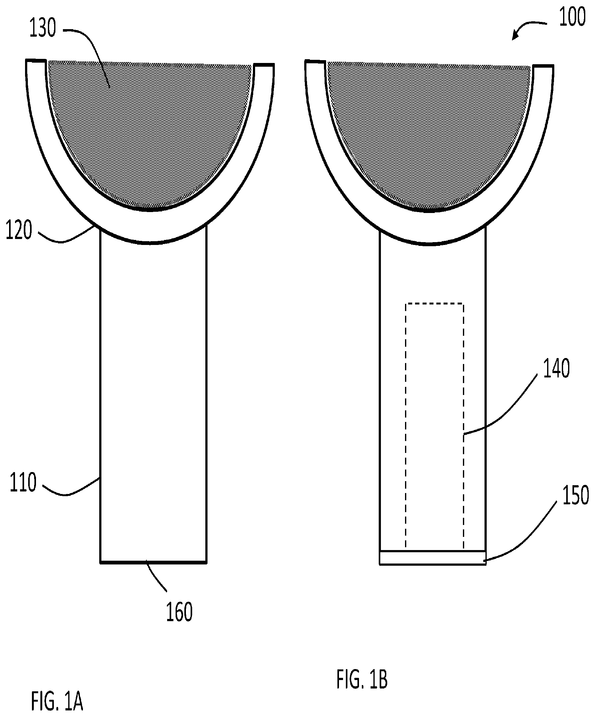
[0020] FIGS. 1A-1C show diagrams of a hand-held piece of sports equipment 100, such as a platform tennis paddle, with a heated handle. The paddle 100 includes a handle portion 110, a frame portion 120, and a face portion 130. The frame portion 120 and face portion 130 are only partially shown; however, these portions may vary from sport to sport and be composed of any shape, weight, or material that is required to comply with the rules of the corresponding sport. Depending on the sport, the face portion 130 may be strung (i.e., for tennis), perforated (i.e., for platform tennis), or solid (i.e., for table tennis).
[0021] The face portion 130, if perforated or solid, may be made of a homogeneous material or made of a first material core and a second material outer layer. In some embodiments, the handle portion 110, the frame portion 120, and the face portion 130 may all be made of the same material and/or may be of a unitary construction. In other embodiments, the handle portion 110, the frame portion 120, and the face portion 130 may all be made of different materials.
[0022] In a preferred embodiment of the present invention, the handle portion 110 is preferably wrapped in a thermoelectric fabric 160 that is configured to convert electrical energy into heat to warm the hand of a user holding the handle 110. Suitable thermoelectric fabrics may include, but are not limited to, conductive metal yarn.
[0023] FIG. 1B shows another diagram of the paddle 100, further comprising a hidden chamber 140 for housing a power module 190 (see FIG. 2). The handle portion 110 may optionally include a cover or end cap 150 for sealing the chamber 140 to prevent moisture from entering therein and/or to prevent the power module 190 from falling out of the chamber 140. The end cap 150 may be secured to the handle 110 by an adhesive, fastener, or both.
[0024] FIG. 1C shows a diagram of the handle portion 110 with the thermoelectric fabric 160 partially unwrapped. The underlying handle surface 170 is adjacent to a wrapped portion 180. The thermoelectric fabric 160 can be wrapped one or more times around the handle portion 110. In some embodiments, the wrapped portion 180 may not fully encompass the underlying handle surface 170. Not shown is a grip that may wrapped over the portion 180, wherein the grip will come in direct contact with the hand of a user.
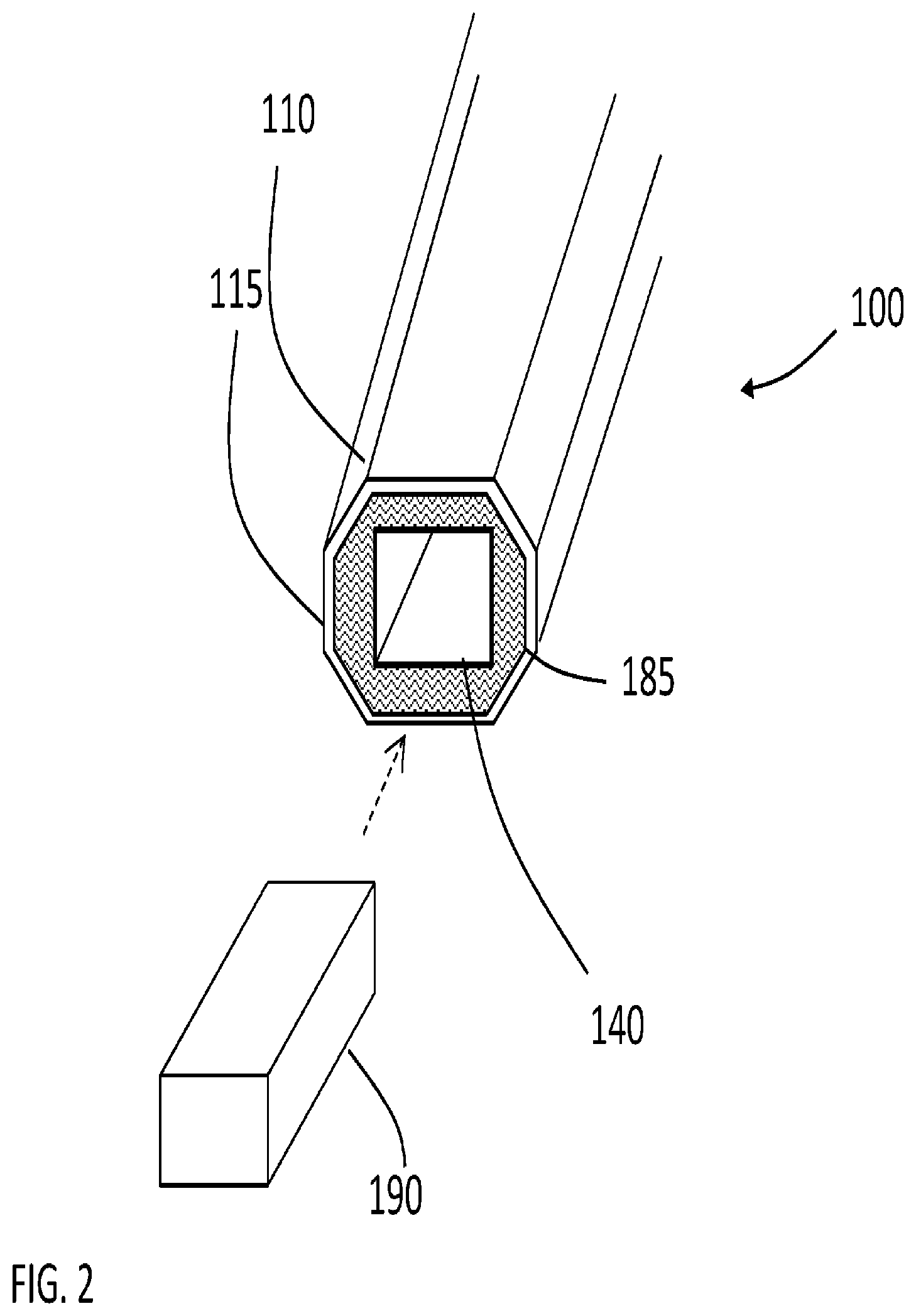
[0025] FIG. 2 shows a three-dimensional drawing of a power module 190 being inserted into the chamber 140 in the handle portion 110. The power module 190 may include a battery either commonly commercially available or custom designed to fit in the chamber 140. The battery may be rechargeable or nonchargeable. The power module 190 may include a power regulator, such as an integrated circuit chip, to control the amount of power to the thermoelectric fabric 160. The power module 190 may include a temperature sensor to control the temperature of the handle portion 110. The temperature of the handle portion 110 may be adjustable using a user interface or similar device. The power module 190 may include a switching circuit for turning the power on/off. In some embodiments, the switching circuit may be on the exterior of the handle portion 110.
[0026] As discussed, the handle portion 110 preferably includes a housing 115 and the chamber 140. The housing 115 may be made of a suitable racquet or paddle material, such as carbon fiber, fiber glass, composite, graphite, or wood (depending on the sport). The chamber 140 may be surrounded by a filler material 185. In some embodiments, the chamber 140 is formed by a gap in the filler material 185. The filler material 185 may secure the power module 190 to prevent movement and stress on electric wires when the paddle 100 is in use. The filler material 185 may also dampen vibration and/or act as a shock absorber to protect the power module 190 from being damaged. The filler material 185 may be made of polyurethane foam. The use of polyurethane foam is illustrative and exemplary only, as other materials may be used that are shock absorbing and not electrically conductive.
[0027] FIG. 3 shows a three-dimensional diagram of one embodiment of the handle portion 110 with the power module 190. Electrical power wires 310 may extend from the thermoelectric fabric 180 through the housing 115 and filler material 185 to a connector 320 that is configured to mate with a corresponding connector 330 on the power module 190.
[0028] FIG. 4 shows a three-dimensional diagram of another embodiment of the handle portion 110 with the power module 190. The top handle end of the power module 190 includes power connectors 410 for plugging into a corresponding set of connectors (not shown) inside the handle portion 110 accessible within the chamber 140. In some embodiments, the power module 190 may include features of FIGS. 3 and 4, wherein the power connectors 410 are used to power the thermoelectric fabric 180 and the power connectors 330 are used to recharge the power module 190.
[0029] It is also contemplated that the power module 190 may be charged wirelessly and controlled (i.e., status checked, temperature controlled, etc.) using a smartphone or similar device. It is further contemplated that paddle 100 may comprise a user interface for observing a status and/or changing a setting of the power module 190 and a temperature of the handle 110.
[0030] While embodiments in the present disclosure have been described in some detail, according to the preferred embodiments illustrated above, such are not meant to be limiting to modifications such as would be obvious to those skilled in the art.
[0031] The foregoing disclosure and description of the disclosure are illustrative and explanatory thereof, and various changes in the details of the illustrated apparatus and system, and the construction and the method of operation may be made without departing from the spirit of the disclosure.
* * * * *
D00000
D00001
D00002
D00003
D00004
XML
uspto.report is an independent third-party trademark research tool that is not affiliated, endorsed, or sponsored by the United States Patent and Trademark Office (USPTO) or any other governmental organization. The information provided by uspto.report is based on publicly available data at the time of writing and is intended for informational purposes only.
While we strive to provide accurate and up-to-date information, we do not guarantee the accuracy, completeness, reliability, or suitability of the information displayed on this site. The use of this site is at your own risk. Any reliance you place on such information is therefore strictly at your own risk.
All official trademark data, including owner information, should be verified by visiting the official USPTO website at www.uspto.gov. This site is not intended to replace professional legal advice and should not be used as a substitute for consulting with a legal professional who is knowledgeable about trademark law.