Apparatus And Method For Intravascular Measurements
Sham; Kin-Joe ; et al.
U.S. patent application number 16/946290 was filed with the patent office on 2020-10-01 for apparatus and method for intravascular measurements. The applicant listed for this patent is ZURICH MEDICAL CORPORATION. Invention is credited to Charles C.H. Chan, James V. Donadio, III, Paul J. Gam, Paul Michael McSherry, Kin-Joe Sham.
| Application Number | 20200305728 16/946290 |
| Document ID | / |
| Family ID | 1000004887429 |
| Filed Date | 2020-10-01 |


| United States Patent Application | 20200305728 |
| Kind Code | A1 |
| Sham; Kin-Joe ; et al. | October 1, 2020 |
APPARATUS AND METHOD FOR INTRAVASCULAR MEASUREMENTS
Abstract
Intravascular diagnosis apparatus and methods are disclosed. In one aspect of the disclosed technology, a intravascular diagnosis apparatus includes a monitoring guidewire and a display unit. The monitoring guidewire includes a core wire and a sensor disposed in a distal region of the core wire. The display unit includes a processor and a display screen, and is capable of receiving communication from the monitoring guidewire. The display unit is configured to perform computations using the processor based on communications received from the monitoring guidewire and is configured to display information on the display screen based on the computations. The display unit can be configured to be disposed after a predetermined number of uses or after a predetermined duration of use.
| Inventors: | Sham; Kin-Joe; (Blaine, MN) ; Donadio, III; James V.; (Victoria, MN) ; Chan; Charles C.H.; (Minneapolis, MN) ; McSherry; Paul Michael; (Woodbury, MN) ; Gam; Paul J.; (Arden Hills, MN) | ||||||||||
| Applicant: |
|
||||||||||
|---|---|---|---|---|---|---|---|---|---|---|---|
| Family ID: | 1000004887429 | ||||||||||
| Appl. No.: | 16/946290 | ||||||||||
| Filed: | June 15, 2020 |
Related U.S. Patent Documents
| Application Number | Filing Date | Patent Number | ||
|---|---|---|---|---|
| 14321776 | Jul 1, 2014 | 10702170 | ||
| 16946290 | ||||
| 61985858 | Apr 29, 2014 | |||
| 61841517 | Jul 1, 2013 | |||
| Current U.S. Class: | 1/1 |
| Current CPC Class: | A61B 5/0215 20130101; A61B 2560/0431 20130101; A61B 5/02007 20130101; A61B 2560/028 20130101; A61B 5/7475 20130101; A61B 2560/0204 20130101; A61B 5/742 20130101 |
| International Class: | A61B 5/0215 20060101 A61B005/0215; A61B 5/02 20060101 A61B005/02; A61B 5/00 20060101 A61B005/00 |
Claims
1. A portable display device for displaying fractional flow reserve information, the portable display device comprising: a housing; a display screen in the housing in a folded position before use, wherein pivoting the display screen from the folded position to an open position acts as an ON switch, wherein the portable display device has no capability of being turned off after the display screen is pivoted to the open position; and a processor within the housing, the processor configured to perform fractional flow reserve computations based on sensor measurements and to cause the display screen to display fractional flow reserve information based on the fractional flow reserve computations.
2. The portable display device of claim 1, further comprising at least one non-rechargeable battery within the housing, wherein after the display screen is pivoted to the open position, the at least one non-rechargeable battery operates continuously until it is depleted based on the portable display device having no capability of being turned off after the display screen is pivoted to the open position.
3. The portable display device of claim 1, further comprising a connector configured to be attachable to and detachable from a guidewire, the connector configured to establish a communicative connection with the guidewire when the guidewire is attached to the connector.
4. The portable display device of claim 1, further comprising a wireless receiver configured to wirelessly receive the sensor measurements from a guidewire.
5. The portable display device of claim 1, wherein the sensor measurements are pressure measurements.
6. The portable display device of claim 5, wherein the fraction flow reserve computations are computed based on: recorded pressure measurements proximal to a first stenosis, and distal pressure measurements distal to the first stenosis, the distal pressure measurements being measured after the recorded pressure measurements are recorded.
7. The portable display device of claim 6, wherein the distal pressure measurements are measured distal to the first stenosis and proximal to a second stenosis.
8. The portable display device of claim 6, wherein: the recorded pressure measurements are measured proximal to the first stenosis and proximal to a second stenosis, and the distal pressure measurements are measured distal to the first stenosis and distal to the second stenosis.
9. The portable display device of claim 5, wherein the fraction flow reserve is computed based on: recorded pressure measurements distal to a first stenosis, and proximal pressure measurements proximal to the first stenosis, the proximal pressure measurements being measured after the recorded pressure measurements are recorded.
10. The portable display device of claim 9, wherein the proximal pressure measurements are measured proximal to the first stenosis and distal to a second stenosis.
11. The portable display device of claim 9, wherein: the recorded pressure measurements are measured distal to the first stenosis and distal to a second stenosis, and the proximal pressure measurements are measured proximal to the first stenosis and proximal to the second stenosis.
12. The portable display device of claim 1, further comprising a communications port configured to receive communications that include pressure measurements.
13. The portable display device of claim 12, wherein the processor is configured to perform the fractional flow reserve computations further based on the pressure measurements received at the communications port.
14. The portable display device of claim 12, wherein the processor is capable of performing the fractional flow reserve computations in at least two ways comprising: performing the fractional flow reserve computations based on only the sensor measurements, and performing the fractional flow reserve computations based on the sensor measurements and based on pressure measurements received at the communications port.
15. The portable display device of claim 14, wherein the processor is configured to automatically select one of the at least two ways of performing the fractional flow reserve computations.
16. The portable display device of claim 14, wherein the processor is configured to receive a user selection of one of the at least two ways of performing the fraction flow reserve computations.
17. A handheld display device for displaying fractional flow reserve information, the handheld display device comprising: a housing; a display screen in the housing in a folded position before use, wherein pivoting the display screen from the folded position to an open position acts as an ON switch, wherein the handheld display device has no capability of being turned off after the display screen is pivoted to the open position; and a processor within the housing, the processor configured to perform fractional flow reserve computations based on sensor measurements and to cause the display screen to display fractional flow reserve information based on the fractional flow reserve computations.
18. The handheld display device of claim 17, wherein the housing has a length equal to or less than 30 cm, a width equal to or less than 30 cm, and a depth equal to or less than 30 cm.
19. A portable display device comprising: a housing; a display screen in the housing in a folded position before use, wherein pivoting the display screen from the folded position to an open position acts as an ON switch, wherein the portable display device has no capability of being turned off after the display screen is pivoted to the open position; and a processor within the housing, the processor configured to perform computations based on sensor measurements from a guidewire and to cause the display screen to display information based on the computations.
Description
CROSS-REFERENCE TO RELATED APPLICATIONS
[0001] This application is a continuation of U.S. patent application Ser. No. 14/321,776, filed Jul. 1, 2014, which claims priority to U.S. Provisional Application No. 61/985,858, filed Apr. 29, 2014, and to U.S. Provisional Application No. 61/841,517, filed Jul. 1, 2013. The entire contents of each and every priority application are hereby incorporated by reference herein.
FIELD OF THE INVENTION
[0002] The disclosed technology relates to intravascular diagnosis. More particularly, the disclosed technology relates to diagnosing the severity of stenosis in the vasculature of a patient.
BACKGROUND
[0003] Reduced blood flow due to atherosclerotic occlusion of vessels is a major cause of vascular diseases. Pressure measurements in arterial vessels and particularly in coronary arteries prior to treatment have been used for lesion characterization and treatment selection. More specifically, pressure gradient across a lesion has been clinically used as an indicator for lesion severity. Measurements made during and after treatment allow one to assess therapy efficacy. Existing equipment for monitoring intravascular measurements have multiple, separate parts and bulky monitors. There is, accordingly, continuing interest in improved monitoring equipment.
SUMMARY
[0004] The disclosed technology relates to diagnosing the severity of stenoses in the vasculature of a patient.
[0005] In one aspect of the disclosed technology, an apparatus for intravascular diagnosis includes a monitoring guidewire having a core wire and a sensor disposed in a distal region of the core wire, and a portable display unit configured to be disposed after a predetermined number of uses or after a predetermined duration of use. The portable display unit can include a processor and a display screen, where the portable display unit is capable of receiving communication from the monitoring guidewire, is configured to perform computations using the processor based on communications received from the monitoring guidewire, and is configured to display information on the display screen based on the computations.
[0006] In one embodiment, the portable display unit includes one or more batteries configured to power the portable display unit. In one embodiment, the one or more batteries can be rechargeable by a power source of the portable display unit and/or a power source external to the portable display unit.
[0007] In one embodiment, the portable display unit further includes one or more batteries configured to power the portable display unit for a predetermined duration of use, such that the portable display unit can be configured to be disposed after the one or more batteries are depleted. In one embodiment, the one or more batteries are non-rechargeable. In one embodiment, the portable display unit can be configured to be inoperable after a one uses.
[0008] In one aspect of the disclosed technology, the monitoring guidewire can be configured to be disposed after a single use.
[0009] In one embodiment, the portable display unit and the monitoring guidewire can communicate wirelessly. In one embodiment, the portable display unit includes a connector configured to establish a communicative connection with the monitoring guidewire. In one embodiment, the connector is configured to establish a mechanical connection with the monitoring guidewire to control the guidewire within a vasculature. In one embodiment, a torquer is configured to engage the monitoring guidewire to control the guidewire within a vasculature.
[0010] In one embodiment, the monitoring guidewire includes a housing surrounding the sensor, and the housing can be laser etched to provide flexibility for the housing. In one embodiment, the monitoring guidewire includes a flexible coil surrounding the sensor, with the coil having a relaxed portion over the sensor.
[0011] In one aspect of the disclosed technology, the sensor is a pressure sensor and communication from the monitoring guidewire includes measurements from the pressure sensor. The processor of the portable display unit is capable of computing fractional flow reserve based on pressure measurements from only the pressure sensor in the distal region of the core wire.
[0012] In one embodiment, the fractional flow reserve is a push-forward fraction flow reserve ("FFR") computed as: FFR=(P.sub.sensor-P.sub.ra)/(P.sub.saved-P.sub.ra), where:
[0013] P.sub.saved are moving means over time of recorded pressure measurements proximal to a first stenosis,
[0014] P.sub.sensor are moving means over time of real time pressure measurements distal to the first stenosis, and
[0015] P.sub.ra is a constant.
[0016] In one embodiment, P.sub.saved are moving means over time of recorded pressure measurements proximal to the first stenosis and proximal to a second stenosis. In one embodiment, P.sub.sensor are moving means over time of real time pressure measurements distal to the first stenosis and proximal to a second stenosis. In one embodiment, P.sub.sensor moving means over time of real time pressure measurements distal to the first stenosis and distal to the second stenosis.
[0017] In one embodiment, the fractional flow reserve is a pull-back fraction flow reserve computed as: FFR=(P.sub.saved-)/(P.sub.sensor-P.sub.ra), where:
[0018] P.sub.saved are moving means over time of recorded pressure measurements distal to a first stenosis,
[0019] P.sub.sensor are moving means over time of real time pressure measurements proximal to the first stenosis, and
[0020] P.sub.ra is a constant.
[0021] In one embodiment, P.sub.sensor are moving means over time of real time pressure measurements proximal to the first stenosis and distal to a second stenosis. In one embodiment, P.sub.saved are moving means over time of recorded pressure measurements distal to the first stenosis and distal to a second stenosis. In one embodiment, P.sub.sensor are moving means over time of real time pressure measurements proximal to the first stenosis and proximal to the second stenosis.
[0022] In one embodiment, the portable display unit displays on the display screen the fractional flow reserve. In one embodiment, the portable display unit displays a graph of the pressure measurements.
[0023] In one embodiment, the portable display unit includes a communications port configured to receive communications that include pressure measurements.
[0024] In one embodiment, the fractional flow reserve is a pull-back fraction flow reserve computed as: FFR=(P.sub.sensor-P.sub.ra)/(P.sub.port-P.sub.ra), where:
[0025] P.sub.port are moving means over time of real-time pressure measurements received at the communications port,
[0026] P.sub.sensor are moving means over time of real-time pressure measurements from the pressure sensor disposed in the distal region of the core wire, and
[0027] P.sub.ra is a constant.
[0028] In one embodiment, the portable display unit is configured with capability to compute fractional flow reserve in at least two ways: computing fractional flow reserve based on pressure measurements from only the pressure sensor disposed in the distal region of the core wire, and computing fractional flow reserve based on the pressure measurements from the pressure sensor and based on pressure measurements received at a communications port. In one embodiment, the portable display unit can be configured to automatically use one of the at least two ways of computing fractional flow reserve. In one embodiment, the portable display unit can be configured to automatically select one of the ways of computing fractional flow reserve when a condition is present and can be configured to automatically select another of the at least two ways of computing fractional flow reserve when the condition is absent. In one embodiment, the portable display unit can be configured to permit a user to manually select one of the at least two ways of computing fraction flow reserve.
[0029] In one aspect of the disclosed technology, an apparatus for intravascular diagnosis includes a monitoring guidewire having a core wire and a sensor disposed in a distal region of the core wire, and a handheld display unit configured to be disposed after a predetermined number of uses or after a predetermined duration of use. The handheld display unit can include a processor and a display screen, where the handheld display unit is capable of receiving communication from the monitoring guidewire, is configured to perform computations using the processor based on communications received from the monitoring guidewire, and is configured to display information on the display screen based on the computations. In one embodiment, the handheld display unit can be equal to or less than 30 cm.times.30 cm.times.30 cm in size.
[0030] In one aspect of the disclosed technology, an apparatus for intravascular diagnosis includes a monitoring guidewire having a core wire and a sensor disposed in a distal region of the core wire, and a portable display unit capable of receiving communication from the monitoring guidewire. The portable display unit includes a processor and display screen, and is configured to perform computations using the processor based on communications received from the monitoring guidewire and is configured to display information on the display screen based on the computations. The portable display unit has no capability of being turned off after the display screen is turned on,
[0031] These aspects and embodiments of the disclosed technology are exemplary and do not limit the scope of the disclosed technology, which will be apparent from a reading of the following detailed description and the associated drawings.
BRIEF DESCRIPTION OF THE DRAWINGS
[0032] FIG. 1 is a block diagram of an exemplary intravascular diagnosis apparatus in accordance with the disclosed technology.
[0033] FIG. 2 is a block diagram of an embodiment of the disclosed technology;
[0034] FIG. 3 is a diagram of an exemplary apparatus in accordance with the disclosed technology;
[0035] FIG. 4 is another diagram of an exemplary apparatus in accordance with the disclosed technology;
[0036] FIG. 5 is a diagram of an exemplary distal tip of the disclosed monitoring guidewire;
[0037] FIG. 6 is a diagram of two embodiments of the distal tip of the disclosed monitoring guidewire;
[0038] FIG. 7 is a diagram of one position for the disclosed monitoring guidewire for estimating fractional flow reserve;
[0039] FIG. 8 is a diagram of another position for the disclosed monitoring guidewire for estimating fractional flow reserve;
[0040] FIG. 9 is a flow diagram of exemplary operation of the disclosed technology for computing simultaneous fractional flow reserve;
[0041] FIG. 10 is a flow diagram of exemplary operation of the disclosed technology for computing push-forward fractional flow reserve; and
[0042] FIG. 11 is a flow diagram of exemplary operation of the disclosed technology for computing pull-back fractional flow reserve.
DETAILED DESCRIPTION
[0043] The disclosed technology relates to diagnosing the severity of stenosis in the vasculature of a patient. The disclosed technology can be used as an adjunct to conventional angiographic procedures to provide important quantitative measurements of a blood vessel lumen.
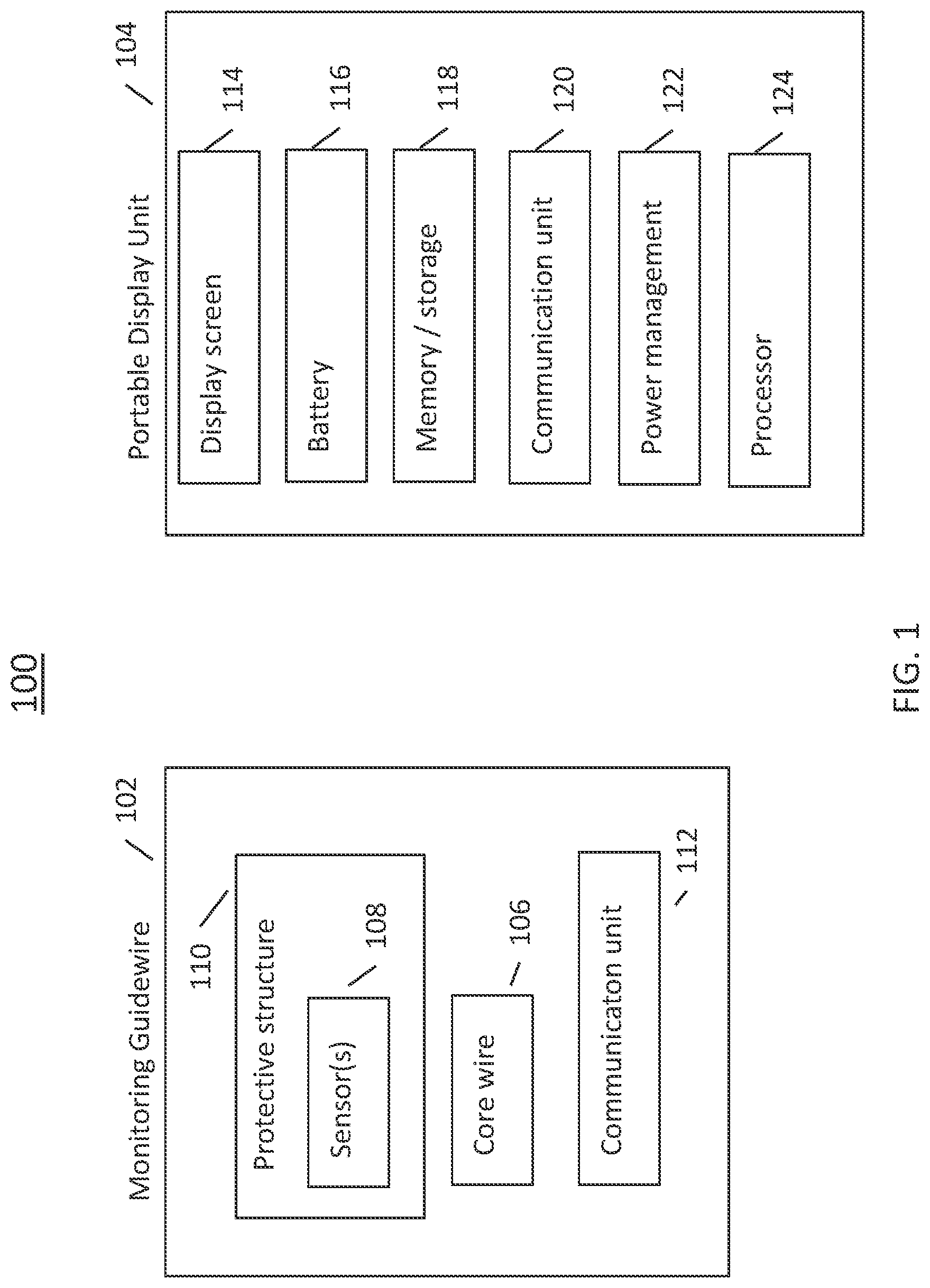
[0044] Referring now to FIG. 1, there is shown a block diagram of an exemplary intravascular diagnosis apparatus in accordance with the disclosed technology. The illustrated apparatus 100 includes a monitoring guidewire 102 and a portable display unit 104. In one embodiment, the portable display unit 104 can be a handheld display unit, such that any and all aspects and embodiments described herein as being applicable to a portable display unit are also applicable to the disclosed handheld display unit. In one embodiment, the handheld display unit can be equal to or less than 30 cm.times.30 cm.times.30 cm in size. In operation, the monitoring guidewire 102 is introduced into the vasculature of a patient with the assistance of conventional interventional equipment known to those skilled in the art, such as catheters. The portable display unit 104 can communicate with the monitoring guidewire 102 and can display information based on the communications received from the monitoring guidewire 102.
[0045] The illustrated monitoring guidewire 102 can include several components, including a core wire 106 and one or more sensors 108 disposed in a distal region of the core wire 106. As used herein, the terms "distal" and "proximal" refer to physical directions within a blood vessel lumen. Specifically, in relation to the insertion point of a device into a patient, the term "distal" refers to the direction from the insertion point inwards into a blood vessel, and the term "proximal" refers to the direction from the inside of a blood vessel out towards the insertion point. As used herein, the terms "proximal" and "distal" can also refer to different ends of a device, with "proximal" being the end towards an insertion point into a blood vessel lumen and with "distal" being the end away from the insertion point.
[0046] With continuing reference to FIG. 1, the one or more sensors 108 disposed in a distal region of the core wire 106 can include one or more hemodynamic pressure sensors and/or one or more temperature sensors. In one embodiment, the pressure sensor(s) can be a piezo-resistive pressure sensor. As illustrated in FIG. 1, the monitoring guidewire 102 can also include a protective structure 110 surrounding the sensor(s) 108, and can include a communication unit 112. The protective structure 110 of the monitoring guidewire 102 will be described in more detail later herein in connection with FIGS. 5-6.
[0047] In one embodiment, the communication unit 112 can employ wireless communication technology such as bluetooth, WiFi (802.11), or any other wireless technology. In one embodiment, the communication unit 112 can be a wireline communication unit that can include one or more wires for communicating electromagnetic signals and/or one or more optical fibers for communicating optical signals. The monitoring guidewire 102 can include other components that are not illustrated, such as a power source, A/D converters, application specific integrated circuits (ASIC), a processor, memory, timing circuitry, and/or other power, analog, or digital circuitry. Such components will be known to those skilled in the art.
[0048] Referring now to the illustrated portable display unit 104, the portable display unit 104 can include a display screen 114, one or more batteries 116, memory and/or storage 118, a communication unit 120, power management unit 122, and a processor 124. In one embodiment, the processor 124 can be a general purpose processor or can be an application specific integrated circuit. In one embodiment, the display screen 114 can be a liquid crystal display, an organic light emitting diode display, or another type of display technology. In one embodiment, the memory/storage 118 can include one or more of solid state memory/storage, magnetic disc storage, and/or any other type of memory/storage that will be known to those skilled in the art. In one embodiment, the memory/storage 118 can include software instructions that are executed by the processor 124. In one embodiment, the communication unit 120 can employ wireless communication technology such as bluetooth, WiFi (802.11), or any other wireless technology. In one embodiment, the communication unit 120 can be a wireline communication unit that can include one or more wires for communicating electromagnetic signals and/or one or more optical fibers for communicating optical signals. The portable display unit 104 can include other components that are not illustrated, such as user interface, operating system software, display driver circuitry, A/D converters, application specific integrated circuits (ASIC), timing circuitry, and/or other power, analog, or digital circuitry. Such components will be known to those skilled in the art.
[0049] Referring now to FIG. 2, there is shown a system block diagram of another embodiment of the disclosed technology. The monitoring guidewire contains a pressure sensor and/or other sensors at the distal end. The electrical signals from the sensor(s) can be sent over a wire connection to the portable display unit. The portable display unit can include a communications port that receives external sensor input such as aortic output pressure (AO IN) from pressure transducers/hemodynamic systems (not shown). The portable display unit can also include an output communication port for outputting data to an external storage device, to another display, to a printer, and/or to a hemodynamic system (not shown).
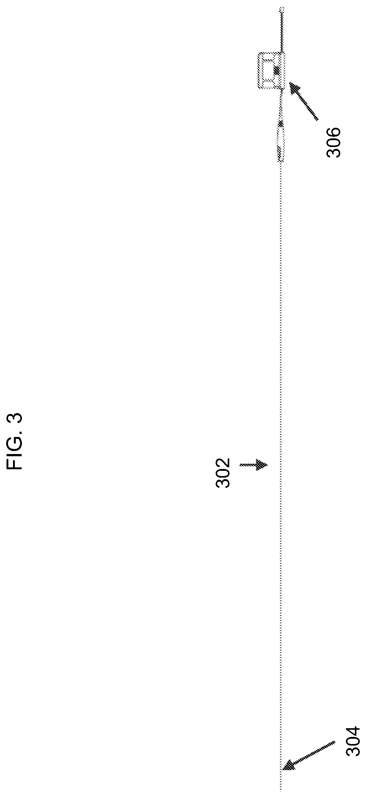
[0050] Referring now to FIG. 3, there is shown an exemplary embodiment of the disclosed intravascular diagnosis apparatus. In one embodiment, the monitoring guidewire 302 can be approximately 180 centimeters in length. In other embodiments, the monitoring guidewire 302 can be another length. The monitoring guidewire 302 can have one or more sensors in the distal region 304 of the monitoring guidewire 302. In the illustrated embodiment, the portable display unit 306 can have a small form factor such that it is a handheld display unit. In one embodiment, a handheld display unit can be equal to or less than 30 cm.times.30 cm.times.30 cm in size.
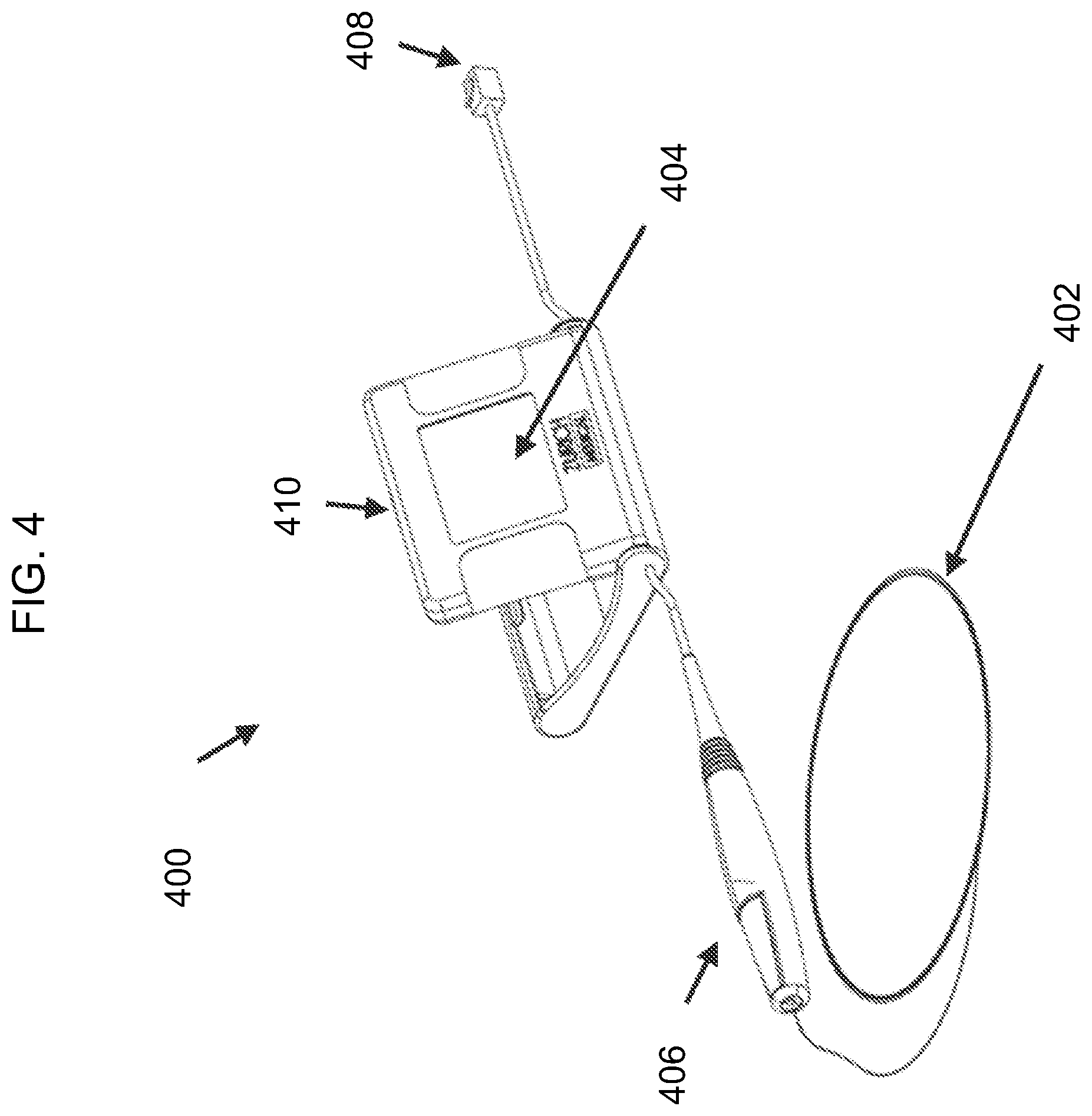
[0051] FIG. 4 is a diagram of another exemplary embodiment of the disclosed intravascular diagnosis apparatus. In the illustrated embodiment, the monitoring guidewire 402 can be attached and detached from a connector 406 of the portable display unit 400. In one embodiment, the connector 406 can include a button (not shown) which opens an aperture in the connector 406. To attach or detach the monitoring guidewire 402, a user can press and hold the button of the connector 406 and insert the monitoring guidewire 402 into the aperture until the monitoring guidewire 402 is fully inserted into connector 406. Once inserted, the user can release the button, which will then secure the monitoring guidewire 402 in place and provide a connection between the monitoring guidewire 402 and connector 406. In other embodiments, the connector 406 can engage the monitoring guidewire 402 by a screw engagement, a twist engagement, a snap engagement, or an interference fit. The described types of engagement are exemplary and do not limit the scope of the disclosed technology. Other types of ways for the connector 406 to engage the monitoring guidewire 402 are contemplated to be within the scope of the disclosed technology.
[0052] In one embodiment, the connector connection establishes a communicative connection between the monitoring guidewire 402 and the portable display unit 400. The monitoring guidewire 402 and the connector 406 can contain electrical wires that connect the monitoring guidewire 402 to the portable display unit 400 and convey signals from the monitoring guidewire sensor(s) to the portable display unit 400.
[0053] In one embodiment, the connector connection establishes a mechanical connection between the monitoring guidewire 402 and the connector 406 to control the guidewire 402 within a vasculature. In the illustrated embodiment, the connector 406 is tethered to the main housing 410 of the portable display unit 400. In one embodiment, the tether can be 6 inches to 12 inches long and can allow a user to manipulate the monitoring guidewire 402 freely without the portable display unit main housing 410 being an impediment. In one embodiment, the tether can be another length. In one embodiment (not shown), the connector can be a connection port integrated in the portable display unit main housing 410.
[0054] In one embodiment, the connector 406 establishes a communicative connection with the monitoring guidewire 402. In one embodiment, a torquer (not shown) can be configured to engage the monitoring guidewire 402 to control the guidewire within a vasculature when the monitoring guidewire 402 is not mechanically and/or electrically connected to the connector 406. In one embodiment, the torquer can be configured to engage the monitoring guidewire 402 to control the guidewire within a vasculature when the monitoring guidewire 402 is mechanically and/or electrically connected to the connector 406. In one embodiment, the monitoring guidewire 402 does not need a torquer or the connector 406 for insertion into the vasculature of a patient and for navigation therein, and provides this capability by itself.
[0055] With continuing reference to FIG. 4, the portable display unit 400 includes a display screen 404 that can display sensor measurements and/or computed information (e.g., fractional flow reserve ratio), in numerical format and/or in waveform format. The portable display unit 400 can include one or more buttons (not shown) or a touch screen to allow a user to provide input to the portable display unit 400. In one embodiment, the screen 404 of the portable display unit can be folded in the main housing 410 before use to minimize the size of packaging when delivering the portal display unit 400. When a user takes the portable display unit 400 out of the packaging for use, the user can pivot the screen 404 from the folded position to an open position (as illustrated), providing an appropriate viewing angle to the user for the diagnosis procedure. In one embodiment, pivoting of the display screen 404 from the folded position to an open position acts as an ON switch that enables power to be delivered to the portable display unit.
[0056] In the illustrated embodiment, the portable display unit 400 also includes a communication port 408. In one embodiment, the communication port 408 allows a user to connect the portable display unit 400 to an external system (not shown). The external system can communicate a sensor signal to the portable display unit 400 through the communication port 408. In one embodiment, the sensor signal received at the communication port can be can be a pressure measurement and can be used in calculating fractional flow reserve.
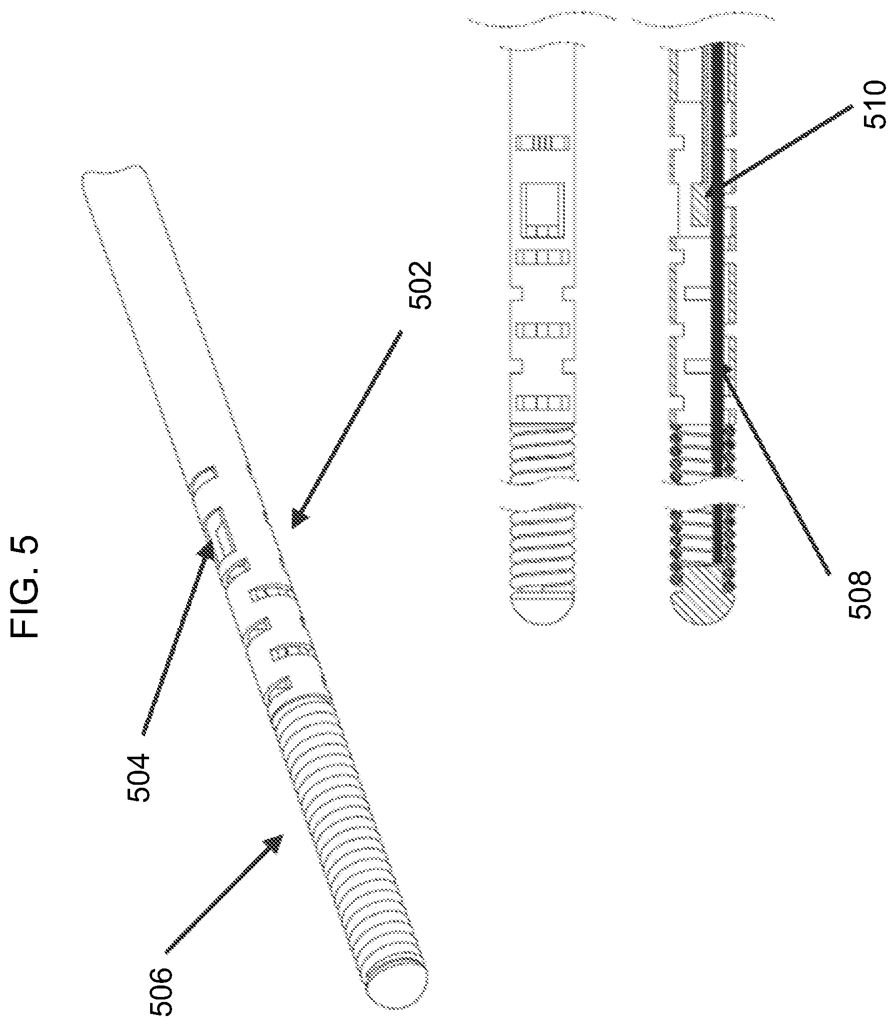
[0057] Referring again to FIG. 1, the monitoring guidewire 102 can include a protective structure 110 surrounding the sensor(s) 108. With reference to FIG. 5, there is shown a diagram of an exemplary protective structure 502 surrounding the sensor(s) 510 at the distal region of the monitoring guidewire. In the illustrated embodiment, the protective structure 502 is a housing that has been laser etched with a particular pattern cut to provide flexibility and/or torque translation at the distal tip or portion of the monitoring guidewire where the sensor 510 resides. The sensor(s) 510 can be situated in the laser etched housing at a window 504 in the housing so as to allow blood to contact the sensor(s) 510 in order to take sensor measurements. In the illustrated embodiment, the core wire 508 can be grinded to provide an appropriate profile for balancing flexibility and torque translation. In one embodiment, the monitoring guidewire need not include a core wire 508. Rather, the protective structure 502 can extend along the entire monitoring guidewire or a substantial portion thereof, and can be laser etched along some or all portions to provide desired flexibility and/or torque translation.
[0058] Referring to FIG. 6, there is shown a diagram of two exemplary protective structures surrounding the sensor(s) at the distal region of a monitoring guidewire. One of the embodiments is a laser etched housing as described in connection with FIG. 5. The other embodiment provides a coil over the sensor(s) as the protective structure. The coil is relaxed to create a window where the sensor(s) are located to allow blood to contact the sensor(s). The illustrated embodiments are exemplary and do not limit the scope of protective structures contemplated in the disclosed technology. Other protective structures are contemplated to be within the scope of the disclosed technology.
[0059] Various aspects and embodiments of the disclosed technology have been described above. The illustrations and descriptions are merely exemplary and do not limit the scope of the disclosed technology. Even though not illustrated, various embodiments can be combined and are contemplated to fall within the scope of the disclosed technology. Furthermore, although certain features are illustrated as being in a particular location or device, the location and device are merely exemplary, and it is contemplated that various features can be located differently than as illustrated and still be within the scope of the disclosed technology.
[0060] The following description will now reference FIG. 1, and in particular, the battery 116 and the power management unit 122 of the portable display unit 104. In one aspect of the disclosed technology, the portable display unit 104 can be configured to operate for a predetermined duration or for a predetermined number of uses, and then be disposed. The battery 116 and/or power management unit 122 can implement these features so that the portable display unit 104 can be inoperable after being used for a particular duration or for a particular number of diagnosis procedures. Even so, the portable display unit 104 can be disposed while it is still operable, prior to it being inoperable.
[0061] In one embodiment, the predetermined duration can correspond to the approximate length of time of a single intravascular diagnosis procedure. In one embodiment, the predetermined duration can correspond to the approximate length of time of multiple diagnosis procedures, such as three procedures. In one embodiment, the predetermined duration can be twelve hours or twenty-four hours or several days. In one aspect of the disclosed technology, the portable display unit 104 can include one or more batteries 116 that are configured to power the portable display unit 104 for the desired duration, such that the batteries 116 are substantially depleted at the end of the desired duration. In one embodiment, the one or more batteries 116 are non-rechargeable, so that the portable display unit 104 is disposed after the batteries 116 are depleted. In one embodiment, the power management unit 122 can control the operating time of the portable display unit 104 by preventing the portably display unit 104 from powering down after the display screen 114 is turned on. In such an embodiment, the portable display unit 104 will operate continuously until the batteries 116 are depleted or substantially depleted. The portable display unit 104 can be disposed prior to the batteries 116 being depleted, while the portable display unit 104 is still operable.
[0062] In one embodiment, the portable display unit 104 can track the number of diagnosis procedures performed and can be configured to be inoperable after a particular number of procedures has been performed. In one embodiment, the portable display unit 104 can track the number of diagnosis procedures performed by the number of times the portable display unit 114 has been turned on and/or off. In one embodiment, the portable display unit 104 can be configured to be inoperable after a single diagnosis procedure has been performed. In one aspect of the disclosed technology, the power management unit 122 can prevent the portable display unit 104 from being powered on after the particular number of procedures has been reached. The batteries 116 can be rechargeable and can be recharged by a power source of the portable display unit 104 and/or by a power source external to the portable display unit 104. Even when the batteries 116 are not yet depleted, the power management unit 122 can cause the portable display unit 104 to be inoperable by preventing the batteries 116 from powering the portable display unit 104.
[0063] The intravascular diagnosis procedure will now be described with continuing reference to FIG. 1 and with reference to FIGS. 7-11. Diagnosing the severity of one or more stenoses within the vasculature of a patient has been studied based on hemodynamic pressure measurements distal to a stenosis in comparison with aortic output pressure. The ratio of pressure distal to a stenosis to the aortic output pressure is known as "factional flow reserve", or FFR. The value of the FFR indicates the severity of the stenosis, and clinical data provides guidance on the type of surgical procedure that would be effective for particular FFR ranges.
[0064] The disclosed technology includes multiple ways of computing FFR, including what will be referred to herein as "push-forward FFR", "pull-back FFR", and "simultaneous FFR". Each of these can be implemented by software code or machine code stored in memory/storage 118 of the portable display unit 104 (FIG. 1). The processor 124 can execute the software code to compute the FFR, and the resulting information can be displayed on the display screen 114. Each of the computation methods will now be described.
[0065] Simultaneous Fraction Flow Reserve
[0066] Simultaneous FFR involves simultaneous pressure readings from two separate pressure sensors, and a computation of FFR in real-time as the pressure readings from the two separate pressure sensors are received. Referring to FIG. 1 and FIG. 9, one pressure sensor is located in the monitoring guidewire 102, and is used to measure pressure distal to a stenosis in a patient. The pressure readings can be communicated by the communication unit 112 of the monitoring guidewire 102 to the communication unit 120 of the portable display unit 104 (902). This communication can be a wireless communication or can be a wireline communication through, for example, the connector illustrated in FIG. 3. The other pressure sensor can measure aortic output pressure and is external to the apparatus 100 of FIG. 1. The portable display unit 104 can designate the received pressure measurements as pressure distal to a stenosis (904). The external sensor readings can be communicated to the communication unit 120 of the portable display unit by, for example, the communication port illustrated in FIG. 3 (906). The portable display unit 104 can designate the received pressure measurements as pressure proximal to a stenosis (908). The portable display unit 104 can compute the simultaneous FFR as the pressure measurements are received (910), by the formula: FFR=(P.sub.sensor-P.sub.ra)/(P.sub.port-P.sub.ra), where:
[0067] P.sub.port are moving means over time of real-time pressure measurements received at the communications port,
[0068] P.sub.sensor are moving means over time of real-time pressure measurements from the pressure sensor in the distal region of the core wire of the monitoring guidewire, and
[0069] P.sub.ra is a constant, which can be zero or another constant value.
[0070] In one embodiment, the moving means over time can compute the mean over a window of time that spans one heartbeat. In other embodiments, the window of time can span less than one heartbeat or more than one heartbeat. As new sensor measurements are received over time (902, 906), the window can include newer measurements and remove older measurements to compute the moving means.
[0071] The portable display unit 104 can receive pressure measurements and can compute the simultaneous FFR based on the received measurements. The portable display unit 104 can store the received pressure measurements and/or the computed simultaneous FFR in memory/storage 118, and can display the computed simultaneous FFR and/or a graph of the received pressure measurements on the display screen 114 (912).
[0072] Push-Forward Fractional Flow Reserve
[0073] In contrast to simultaneous FFR, the push-forward FFR does not receive external pressure measurements. With continuing reference to FIG. 1, push-forward FFR is computed using pressure measurements from only the pressure sensor(s) 108 in the distal region of the monitoring guidewire 102. Using traditional angiography, a stenosis can be located and, as shown in FIG. 8, the monitoring guidewire can be inserted into a patient to a point proximal to the stenosis. Pressure can be measured at this position by the sensor(s) 108 and communicated by the communication unit 112 to the portable display unit 104 (1002). The portable display unit 104 can store the measurements in this position in the memory/storage 118 as pressure proximal to a stenosis (1004). Next, the monitoring guidewire 102 can be pushed forward past the stenosis to a point distal to the stenosis, as illustrated in FIG. 7. Pressure can be measured at this position by the sensor(s) 108 and communicated by the communication unit 112 to the portable display unit 104 (1006). The portal display unit 104 can designate the pressure measurements received at this position as pressure distal to the stenosis (1008). The processor 124 can compute the push-forward FFR (1010) by the formula: FFR=(P.sub.sensor-P.sub.ra)/(P.sub.saved-P.sub.ra), where:
[0074] P.sub.saved are moving means over time of recorded pressure measurements proximal to the stenosis,
[0075] P.sub.sensor are moving means over time of real time pressure measurements distal to the stenosis, and
[0076] P.sub.ra is a constant, which can be zero or another constant value.
[0077] Aspects of computing the moving means over time were described above in connection with simultaneous FFR, and such aspects apply to push-forward FFR as well.
[0078] The portal display unit 104 can display the computed push-forward FFR and/or a graph of the received and stored pressure measurements (1012).
[0079] Push-forward FFR can be computed in the case of one stenosis and can also be computed in the case of multiple stenosis. In either case, P.sub.saved are moving means over time of pressure measurements proximal to all of the stenosis. In one embodiment, P.sub.saved are moving means over time computed based on recorded pressure measurements. In one embodiment, P.sub.saved are moving means over time computed and recorded as pressure measurements are received, and the pressure measurements may or may not be recorded. For example, in the case of two stenoses, P.sub.saved are based on pressure measurements proximal to both the first and second stenosis. When the monitoring guidewire pressure sensor 108 is pushed forward to a position between the first and the second stenosis, P.sub.sensor are based on real time pressure measurements between the two stenoses. Push-forward FFR can be calculated in this position and displayed on the display screen 114. When the monitoring guidewire pressure sensor 108 is pushed forward to a position distal to both the first and second stenoses, P.sub.sensor are based on real time pressure measurements distal to both of the two stenoses. Push-forward FFR can be calculated in this position and displayed on the display screen 114. Thus, push-forward FFR enables FFR to be computed and displayed as the monitoring guidewire 102 is pushed forward across one or more stenoses in a blood vessel lumen. The only measurements and/or moving means that need to be recorded for push-forward FFR computations are pressure measurements and/or moving means of pressure measurements proximal to all stenoses, and this is performed at the outset.
[0080] Pull-Back Fractional Flow Reserve
[0081] Similar to push-forward FFR, the pull-back FFR does not receive external pressure measurements. Rather, pull-back FFR is computed using pressure measurements from only the pressure sensor(s) 108 in the distal region of the monitoring guidewire 102. Using traditional angiography, a stenosis can be located and, as shown in FIG. 7, the monitoring guidewire can be inserted into a patient to a point distal to the stenosis. Pressure can be measured at this position by the sensor(s) 108 and communicated by the communication unit 112 to the portable display unit 104 (1102). The portable display unit 104 can store the measurements in this position in the memory/storage 118 as pressure distal to a stenosis (1104). Next, the monitoring guidewire 102 can be pulled back through the stenosis to a point proximal to the stenosis, as illustrated in FIG. 8. Pressure can be measured at this position by the sensor(s) 108 and communicated by the communication unit 112 to the portable display unit 104 (1106). The portable display unit 104 can designate the measurements received in this position as pressure proximal to a stenosis (1108). The processor 124 can compute the pull-back FFR (1110) by the formula:
FFR=(P.sub.saved-P.sub.ra)/(P.sub.sensor-P.sub.ra)
where:
[0082] P.sub.saved are moving means over time of recorded pressure measurements distal to the stenosis,
[0083] P.sub.sensor are moving means over time of real time pressure measurements proximal to the stenosis, and
[0084] P.sub.ra is a constant, which can be zero or another constant value.
[0085] Aspects of computing the moving means over time were described above in connection with simultaneous FFR, and such aspects apply to pull-back FFR as well.
[0086] The portal display unit 104 can display the computed pull-back FFR and/or a graph of the received and stored pressure measurements (1112).
[0087] Pull-back FFR can be computed in the case of one stenosis and can also be computed in the case of multiple stenosis. In either case, P.sub.sensor are based on real-time pressure measurements proximal to all of the stenosis, which are the final pressure measurements that are taken. For example, in the case of two stenoses, the monitoring guidewire pressure sensor 108 is initially placed at a position distal to both the first and the second stenoses. Pressure can be measured at this position by the sensor(s) 108 and communicated by the communication unit 112 to the portable display unit 104. In one embodiment, P.sub.saved_d1 are moving means over time computed later based on recorded pressure measurements. In one embodiment, P.sub.saved_d1 are moving means over time computed and recorded while the pressure measurements are received in this position, and the pressure measurements may or may not be recorded. The memory/storage 118 can record the pressure measurements in this position and/or computed moving means over time based on such pressure measurements. Pull-back FFR cannot yet be calculated because there is no real-time measurement yet proximal to all of the stenoses. Next, the monitoring guidewire 102 can be pulled back through the first stenosis to a point between the first and second stenosis. Pressure can be measured at this position by the sensor(s) 108 and communicated by the communication unit 112 to the portable display unit 104. In one embodiment, P.sub.saved_d2 are moving means over time computed later based on recorded pressure measurements. In one embodiment, P.sub.saved_d1 are moving means over time computed and recorded while the pressure measurements are received in this position, and the pressure measurements may or may not be recorded. The memory/storage 118 can record the pressure measurements in this position and/or computed moving means over time based on such pressure measurements. Once again, pull-back FFR cannot yet be calculated because there is no real-time measurement yet proximal to all of the stenoses. Lastly, the monitoring guidewire 102 can be pulled back through the second stenosis to a point proximal to both the first and second stenosis. Real-time pressure can be measured at this position by the sensor(s) 108 and communicated by the communication unit 112 to the portable display unit 104. Only at this point are there enough measurements to compute the two pull-back FFR: FFR.sub.1=(P.sub.saved_d1-P.sub.ra)/(P.sub.sensor-P.sub.ra) and FFR.sub.2=(P.sub.saved_d2-P.sub.ra)/(P.sub.sensor-P.sub.ra). Therefore, pull-back FFR does not allow FFR to be calculated and displayed as the monitoring guidewire is being pulled back through multiple stenoses.
[0088] Accordingly, three computations for fractional flow reserve have been described above in connection with FIGS. 7-11. In one aspect of the disclosed technology, and with reference to FIG. 1, the portable display unit 104 is configured with capability to compute fractional flow reserve using any of the three ways. In one embodiment, the portable display unit 104 can be configured to automatically use one of the three ways of computing fractional flow reserve. In one embodiment, the portable display unit 104 can be configured to automatically select one of the three ways of computing fractional flow reserve when a condition is present and to automatically select another of the three ways of computing fractional flow reserve when other conditions are present. In one embodiment, the portable display unit 104 can be configured to permit a user to manually select one of the three ways of computing fraction flow reserve.
[0089] The disclosed technology measures pressure and calculates fractional flow reserve (FFR). FFR is a calculation that has been clinically demonstrated to assist in determining whether to treat or not to treat an intermediate coronary lesion. Using the disclosed technology will thus assist a physician in determining what to do with an intermediate lesion. The disclosed FFR equations are exemplary and do not limit the scope of the disclosed technology. Other ways to compute FFR are contemplated to be within the scope of the disclosed technology.
[0090] The illustrations, embodiments, and specifications disclosed herein are exemplary and do not limit the spirit and scope of the disclosed technology. Combinations of one or more disclosed embodiments or specification, or portions of one or more embodiments or specifications, are contemplated as being within the scope of the disclosed technology.
* * * * *
D00000
D00001
D00002
D00003
D00004
D00005
D00006
D00007
D00008
D00009
D00010
XML
uspto.report is an independent third-party trademark research tool that is not affiliated, endorsed, or sponsored by the United States Patent and Trademark Office (USPTO) or any other governmental organization. The information provided by uspto.report is based on publicly available data at the time of writing and is intended for informational purposes only.
While we strive to provide accurate and up-to-date information, we do not guarantee the accuracy, completeness, reliability, or suitability of the information displayed on this site. The use of this site is at your own risk. Any reliance you place on such information is therefore strictly at your own risk.
All official trademark data, including owner information, should be verified by visiting the official USPTO website at www.uspto.gov. This site is not intended to replace professional legal advice and should not be used as a substitute for consulting with a legal professional who is knowledgeable about trademark law.