Curtain Rod Bracket
Hanley; Michael P.
U.S. patent application number 16/775030 was filed with the patent office on 2020-10-01 for curtain rod bracket. The applicant listed for this patent is Kenney Manufacturing Company. Invention is credited to Michael P. Hanley.
| Application Number | 20200305629 16/775030 |
| Document ID | / |
| Family ID | 1000004666939 |
| Filed Date | 2020-10-01 |


| United States Patent Application | 20200305629 |
| Kind Code | A1 |
| Hanley; Michael P. | October 1, 2020 |
CURTAIN ROD BRACKET
Abstract
A curtain rod bracket includes a bracket insert, a mounting plate, an adjustable fastener, and mounting spikes.
| Inventors: | Hanley; Michael P.; (Smithfield, RI) | ||||||||||
| Applicant: |
|
||||||||||
|---|---|---|---|---|---|---|---|---|---|---|---|
| Family ID: | 1000004666939 | ||||||||||
| Appl. No.: | 16/775030 | ||||||||||
| Filed: | January 28, 2020 |
Related U.S. Patent Documents
| Application Number | Filing Date | Patent Number | ||
|---|---|---|---|---|
| 62823398 | Mar 25, 2019 | |||
| Current U.S. Class: | 1/1 |
| Current CPC Class: | A47H 1/142 20130101; A47H 1/102 20130101 |
| International Class: | A47H 1/142 20060101 A47H001/142; A47H 1/102 20060101 A47H001/102 |
Claims
1. A curtain rod bracket comprising: a bracket insert; a mounting plate; an adjustable fastener; and mounting spikes.
2. The curtain rod bracket of claim 1 wherein the bracket insert is bent, resulting in two sections on either side of the bend.
3. The curtain rod bracket of claim 1 wherein the bracket insert bend is 93.degree..
4. The curtain rod bracket of claim 2 wherein the two sections comprise: a wall section and an extension section.
5. The curtain rod bracket of claim 4 wherein a distal end of the extension section comprises a cradle portion.
6. The curtain rod bracket of claim 5 wherein the cradle portion includes an aperture configured to receive the adjustable fastener.
7. The curtain rod bracket of claim 6 wherein the cradle portion is configured to receive a curtain rod.
8. The curtain rod bracket of claim 4 wherein the mounting plate comprises an upper side and an underside.
9. The curtain rod bracket of claim 8 wherein the upper side of the mounting plate includes a securing aperture, a mounting spike aperture and parallel wall portion receptacles.
10. The curtain rod bracket of claim 8 wherein the upper side of the mounting plate includes a securing aperture, a mounting spike aperture and a wall portion receptacle.
11. The curtain rod bracket of claim 10 wherein the underside of the mounting plate includes a spike.
12. The curtain rod bracket of claim 9 wherein the securing aperture is configured to receive a tack.
13. The curtain rod bracket of claim 9 wherein the wall portion receptacles are configured to receive the wall section of the bracket insert.
14. The curtain rod bracket of claim 13 wherein the underside of the mounting plate includes a spike.
15. The curtain rod bracket of claim 14 wherein the spike is configured to aid in an initial positioning and securing of the mounting plate along a mounting surface.
16. The curtain rod bracket of claim 15 wherein the mounting surface is a top of a window casing.
17. A method comprising: providing a curtain rod bracket, the curtain rod bracket comprising a bracket insert, a mounting plate, an adjustable fastener and mounting spikes; placing a wall section of the bracket insert into a rear wall portion receptacle of the mounting plate; positioning the mounting plate on an upper surface of a window casing with a spike of the mounting plate facing downward; and taping the mounting plate on to upper surface of a window casing, causing the spike to penetrate the window casing.
18. The method of claim 17 further comprising: driving mounting spikes through a securing aperture and a mounting spike aperture of the mounting plate and into the window casing.
Description
CROSS REFERENCE TO RELATED APPLICATIONS
[0001] This application claims benefit from U.S. Provisional Patent Application Ser. No. 62/823,398, filed Mar. 25, 2019, which is incorporated by reference in its entirety.
STATEMENT REGARDING GOVERNMENT INTEREST
[0002] None.
BACKGROUND OF THE INVENTION
[0003] This invention generally relates to brackets for supporting rods or rails for supporting rods, and more specifically to a curtain rod bracket.
[0004] In general, brackets have been used in the hardware industry for mounting curtain rods, shower curtain rods, and other rods to surfaces such as walls, windows, window frames, window casings, and ceilings. Brackets often include a hook-like feature in which a rod rests or a ring through which the rod passes.
[0005] One problem in using brackets of such construction is that nails or screws cause holes in the front face of the molding or the surrounding wall and after several repositionings, the wall may become damaged or the molding may become honeycombed with holes or even split. Thus, there remains a need in the hardware industry and arts for a bracket system which, when used to support curtain rods on wooden and other moldings, does not require screws or nails for prepositioning to the molding.
SUMMARY OF THE INVENTION
[0006] The following presents a simplified summary of the innovation in order to provide a basic understanding of some aspects of the invention. This summary is not an extensive overview of the invention. It is intended to neither identify key or critical elements of the invention nor delineate the scope of the invention. Its sole purpose is to present some concepts of the invention in a simplified form as a prelude to the more detailed description that is presented later.
[0007] In general, in one aspect, the invention features a curtain rod bracket including a bracket insert, a mounting plate, an adjustable fastener, and mounting spikes.
[0008] In another aspect, the invention features a method including providing a curtain rod bracket, the curtain rod bracket including a bracket insert, a mounting plate, an adjustable fastener and mounting spikes, placing a wall section of the bracket insert into a rear wall portion receptacle of the mounting plate, positioning the mounting plate on an upper surface of a window casing with a spike of the mounting plate facing downward, and taping the mounting plate on to upper surface of a window casing, causing the spike to penetrate the window casing.
[0009] These and other features and advantages will be apparent from a reading of the following detailed description and a review of the associated drawings. It is to be understood that both the foregoing general description and the following detailed description are explanatory only and are not restrictive of aspects as claimed.
BRIEF DESCRIPTION OF THE DRAWINGS
[0010] These and other features, aspects, and advantages of the present invention will become better understood with reference to the following description, appended claims, and accompanying drawings where:
[0011] FIG. 1 is a diagram of a first embodiment of an exemplary curtain rod bracket.
[0012] FIG. 2 is a component diagram of an exemplary curtain rod bracket of FIG. 1.
[0013] FIG. 3 is a diagram of a bracket insert.
[0014] FIG. 4 is a diagram of a mounting plate.
[0015] FIG. 5 is a diagram of an underside of the mounting plate of FIG. 4.
[0016] FIGS. 6A, 6B and 6C illustrate mounting of the exemplary curtain rod bracket of FIG. 1.
[0017] FIG. 7 is a diagram of a second embodiment of an exemplary curtain rod bracket.
[0018] FIG. 8 is a diagram of an underside of the mounting plate of FIG. 7.
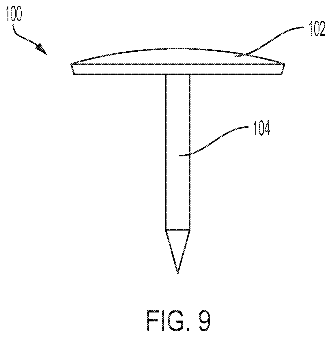
[0019] FIG. 9 is a diagram of an exemplary mounting spike.
DETAILED DESCRIPTION
[0020] The subject innovation is now described with reference to the drawings, wherein like reference numerals are used to refer to like elements throughout. In the following description, for purposes of explanation, numerous specific details are set forth in order to provide a thorough understanding of the present invention. It may be evident, however, that the present invention may be practiced without these specific details. In other instances, well-known structures and devices are shown in block diagram form in order to facilitate describing the present invention.
[0021] As shown in FIGS. 1-4, a first embodiment of an exemplary curtain rod bracket 10 includes a bracket insert 12, a mounting plate 14, an adjustable fastener 16 and mounting spikes 18. The bracket insert 12 is bent, resulting in two sections, i.e., a wall section 20 and an extension section 22. A distal end of the extension section 22 includes a cradle portion 24. The cradle portion 24 includes an aperture 26 configured to receive the adjustable fastener 16.
[0022] The bend in the bracket insert 12 is such so as to provide stability to assembled curtain rod bracket 10 when properly mounted to a casing. In a preferred embodiment, the bend in the bracket insert 12 is 93.degree..
[0023] The cradle portion 24 is configured to receive a rod (not shown), such as a curtain rod. Once the rod is placed into the cradle portion 24, the adjustable fastener 16 is placed onto the aperture 26 and rotated until making contact with the rod to secure the rod within the cradle portion 24. In one example, the aperture 26 is threaded to received corresponding threads of the adjustable fastener 16.
[0024] An upper side 28 of the mounting plate 14 includes a securing aperture 30, a mounting spike aperture 32 and two parallel wall portion receptacles 34, 36. The securing aperture 30 is configured to receive a tack (not shown). Each of the wall portion receptacles 34, 36 is configured to receive the wall section 20 of the bracket insert 12. The presence of two wall portion receptacles 34, 36 enable the wall section 20 to be positioned in one of two different positions with respect to a mounting surface (not shown).
[0025] As shown in FIG. 5, an underside (or back) 40 of the mounting plate 14 includes a spike 42. The spike 42 aids in initial positioning and securing of the mounting plate 14 along a mounting surface, such as, for example, a top of a window casing.
[0026] FIGS. 6A, 6B and 6C illustrate one method of attaching and securing he curtain rod bracket 10 on to a window casing. In FIG. 6A, the wall section 20 of the curtain rod bracket 10 is placed through the rear wall portion receptacle 36 of the mounting plate 14. In FIG. 6B, the mounting plate 14 is positioned on an upper surface of, for example, a first edge 60 of a window casing 62 with the spike 42 facing downward. Once positioned on the window casing 62, the mounting plate 14 is tapped, for example, with a hammer, causing the spike 42 to penetrate the upper surface of the window casing 62. The result is the mounting mounting plate 14 becoming approximately flush with the upper surface of the window casing 62 and the wall section 20 of the curtain rod bracket 10 approximately flush with a surface such as a wall. In FIG. 6C, the two mounting spikes 18 are then driven through the securing aperture 30 and mounting spike aperture 32, securing the curtain rod bracket 10 on to the window casing 62. The mounting spikes 18 can be any appropriate spike, such as nails. In a preferred embodiment, the mounting spikes 18 are thumb tacks.
[0027] The steps shown in FIGS. 6A, 6B and 6C are then repeated for installation of another mountain bracket on another side of the window casing 62.
[0028] As shown in FIGS. 7 and 8, another exemplary embodiment of a curtain rod bracket 70 includes a bracket insert 72, a mounting plate 74 and an adjustable fastener 76. In this embodiment, a top of the mounting plate 74 includes a frontal wall receptacle 78 configured to receive a wall section 80 of the bracket insert 72. The top of the mounting plate 74 also includes two securing apertures 82a, 82b and a mounting spike aperture 84. A backside (or underside) 86 of the mounting plate 74 includes a spike 88 that aids in initial positioning and securing of the mounting plate 74 along a mounting surface, such as, for example, a top of a window casing.
[0029] The bracket insert 72 an extension section 90. A distal end of the extension section 90 includes a cradle portion 92. The cradle portion 92 includes an aperture 94 configured to receive the adjustable fastener 76.
[0030] The cradle portion 92 is configured to receive a rod (not shown), such as a curtain rod. Once the rod is placed into the cradle portion 92, the adjustable fastener 76 is placed onto the aperture 94 and rotated until making contact with the rod to secure the rod within the cradle portion 92. In one example, the aperture 94 is threaded to received corresponding threads of the adjustable fastener 76.
[0031] The curtain rod bracket 70 may be used, for example, in a central position along a top of a window casing to add strength and stability to a heavy and/or long rod.
[0032] In FIG. 9, an exemplary mounting spike 100 is illustrated. The mounting spike 100 includes a cold rolled steel head 102 a top of a cold drawn wire 104.
[0033] It would be appreciated by those skilled in the art that various changes and modifications can be made to the illustrated embodiments without departing from the spirit of the present invention. All such modifications and changes are intended to be within the scope of the present invention except as limited by the scope of the appended claims.
* * * * *
D00000
D00001
D00002
D00003
D00004
D00005
D00006
XML
uspto.report is an independent third-party trademark research tool that is not affiliated, endorsed, or sponsored by the United States Patent and Trademark Office (USPTO) or any other governmental organization. The information provided by uspto.report is based on publicly available data at the time of writing and is intended for informational purposes only.
While we strive to provide accurate and up-to-date information, we do not guarantee the accuracy, completeness, reliability, or suitability of the information displayed on this site. The use of this site is at your own risk. Any reliance you place on such information is therefore strictly at your own risk.
All official trademark data, including owner information, should be verified by visiting the official USPTO website at www.uspto.gov. This site is not intended to replace professional legal advice and should not be used as a substitute for consulting with a legal professional who is knowledgeable about trademark law.