Traction Elements For Athletic Shoes And Methods Of Manufacture Thereof
Burt; John Robert ; et al.
U.S. patent application number 16/903643 was filed with the patent office on 2020-10-01 for traction elements for athletic shoes and methods of manufacture thereof. This patent application is currently assigned to Pride Manufacturing Company, LLC. The applicant listed for this patent is Pride Manufacturing Company, LLC. Invention is credited to John Robert Burt, Lee Shuttleworth.
| Application Number | 20200305556 16/903643 |
| Document ID | / |
| Family ID | 1000004916587 |
| Filed Date | 2020-10-01 |


| United States Patent Application | 20200305556 |
| Kind Code | A1 |
| Burt; John Robert ; et al. | October 1, 2020 |
TRACTION ELEMENTS FOR ATHLETIC SHOES AND METHODS OF MANUFACTURE THEREOF
Abstract
Various embodiments for a traction element used with athletic shoes having a stud body with a metal insert that extends axially from the stud body and methods for manufacturing such traction elements are disclosed.
| Inventors: | Burt; John Robert; (Brentwood, TN) ; Shuttleworth; Lee; (Brentwood, TN) | ||||||||||
| Applicant: |
|
||||||||||
|---|---|---|---|---|---|---|---|---|---|---|---|
| Assignee: | Pride Manufacturing Company,
LLC Brentwood TN |
||||||||||
| Family ID: | 1000004916587 | ||||||||||
| Appl. No.: | 16/903643 | ||||||||||
| Filed: | June 17, 2020 |
Related U.S. Patent Documents
| Application Number | Filing Date | Patent Number | ||
|---|---|---|---|---|
| 16290460 | Mar 1, 2019 | |||
| 16903643 | ||||
| Current U.S. Class: | 1/1 |
| Current CPC Class: | A43C 15/161 20130101; A43C 15/167 20130101; A43B 5/02 20130101 |
| International Class: | A43C 15/16 20060101 A43C015/16; A43B 5/02 20060101 A43B005/02 |
Claims
1. A method of manufacturing a traction element comprising: casting a stud body, the stud body having a distal head portion and a proximal end portion; coring out the proximal end portion of the stud body to form an interior cavity; driving a metal insert into the interior cavity of the stud body such that the metal insert cuts into an interior surface of the interior cavity to securely engage the metal insert with the stud body; and inserting a stabilizer disc into the interior cavity of the stud body such that an aperture formed by the stabilizer disc engages the metal insert.
2. The method of claim 1, wherein the metal insert comprises a distal head portion, a proximal threaded portion and a plurality of drive grippers extending radially outward from the proximal threaded portion adjacent the distal head portion.
3. The method of claim 2, wherein driving the metal insert into the interior cavity comprises engaging the plurality of drive grippers with a driving tool and rotating the metal insert into the interior cavity.
4. The method of claim 2, wherein the plurality of drive grippers comprises a plurality of radially extending arms.
5. The method of claim 2, wherein the distal head portion forms a standard or reverse thread head configured for cutting into a surface of the stud body when engaging the metal insert with the stud body.
6. The method of claim 1, wherein the stabilizer disc is inserted into the proximal end of the interior cavity such that an exterior surface of the stabilizer disc contacts a surface of the interior cavity in a press-fit engagement.
7. A traction element comprising; a cored out stud body defining an interior cavity, a distal head portion, and a proximal end portion, the stud body configured to be attached to a sole of a shoe; and the interior cavity of the cored out stud body comprising a light weight filler material; a metal insert coupled to the stud body, the metal insert extending axially from the stud body; and a stabilizer disc engaged with the metal insert and disposed within a proximal end portion of the interior cavity such that an exterior surface of the stabilizer disc contacts a surface of the interior cavity in a press-fit engagement.
8. The traction element of claim 7, wherein the stabilizer disc comprises a ring-shaped body defining an exterior surface and an interior surface forming an aperture, wherein the metal insert is disposed through the aperture of the stabilizer disc such that the stabilizer disc is pushed into the interior cavity of the stud body causing the exterior surface of the stabilizer disc to contact the surface of the interior cavity in a press-fit engagement.
9. The traction element of claim 7, wherein the stud body is thimble shaped, the thimble shaped configured to provide traction and gripping strength along a ground surface.
10. The traction element of claim 7, wherein the metal insert is configured to mechanically couple the traction element to the sole of the shoe.
11. The traction element of claim 7, wherein the proximal end portion of the stud body tapers away from the distal head portion and forms a peripheral flange that defines an opening in communication with an interior cavity formed within the stud body.
12. The traction element of claim 6, wherein the metal insert comprises at least a steel or aluminum material.
13. The traction element of claim 7, wherein a plurality of cutaways may be formed axially along an outer surface of the stud body, the plurality of cutaways collectively configured to receive a driving tool.
14. The traction element of claim 7, wherein each of the plurality of cutaways define an elongated slot configuration forming a base proximate to a peripheral flange of the stud body.
15. The traction element of claim 7, wherein the plurality of cutaways define at least one of a triangularly-shaped slot, a rectangular shaped slot, a symmetrically shaped slot, an asymmetrically shaped slot, and a circular shaped slot.
16. The traction element of claim 7, wherein the metal insert is cast to the stud body.
17. The traction element of claim 7, wherein the metal insert is mechanically coupled to the stud body.
Description
CROSS REFERENCED TO RELATED APPLICATIONS
[0001] This is a continuation-in-part application that claims benefit to U.S. non-provisional application Ser. No. 16/290,460 filed on Mar. 1, 2019, which is herein incorporated by reference in its entirety.
FIELD
[0002] The present disclosure generally relates to traction elements for shoes, and in particular to traction elements for athletic shoes having a reduced weight and methods of manufacturing such traction elements.
BACKGROUND
[0003] Traction elements for athletic shoes are used to provide a gripping surface that produces traction between the sole of the shoe and the athletic surface, such as a grass field. Typically, traction elements for athletic shoes used in sports, such as rugby, use metal studs made of a metallic material to accommodate the high shear forces applied to the metal studs during play. However, there is a desire for a traction element that also reduces the weight of the traction element while still meeting all of the performance, shape specifications and material requirements required by various official sports authorities.
[0004] It is with these observations in mind, among others, that various aspects of the present disclosure were conceived and developed.
BRIEF DESCRIPTION OF THE DRAWINGS
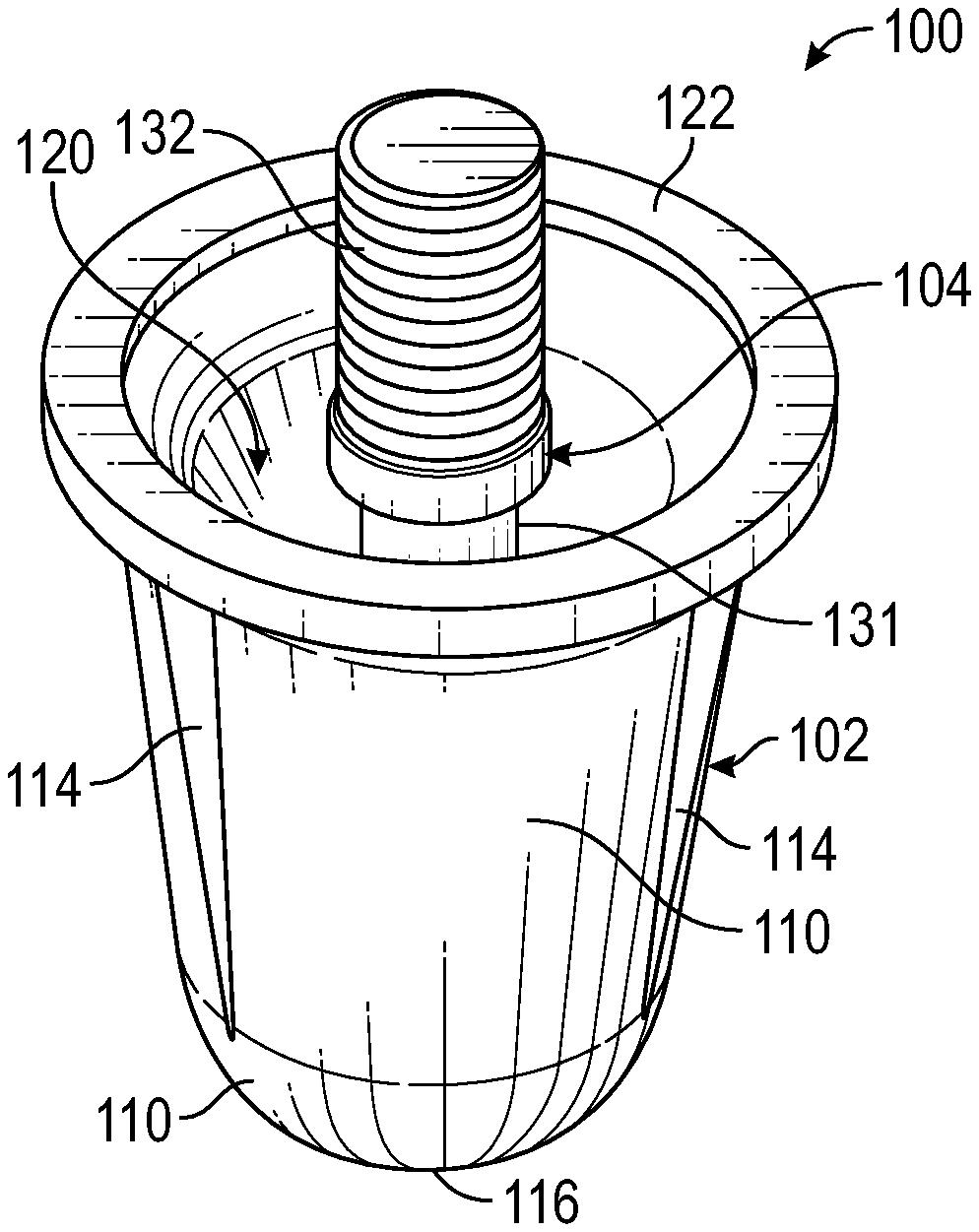
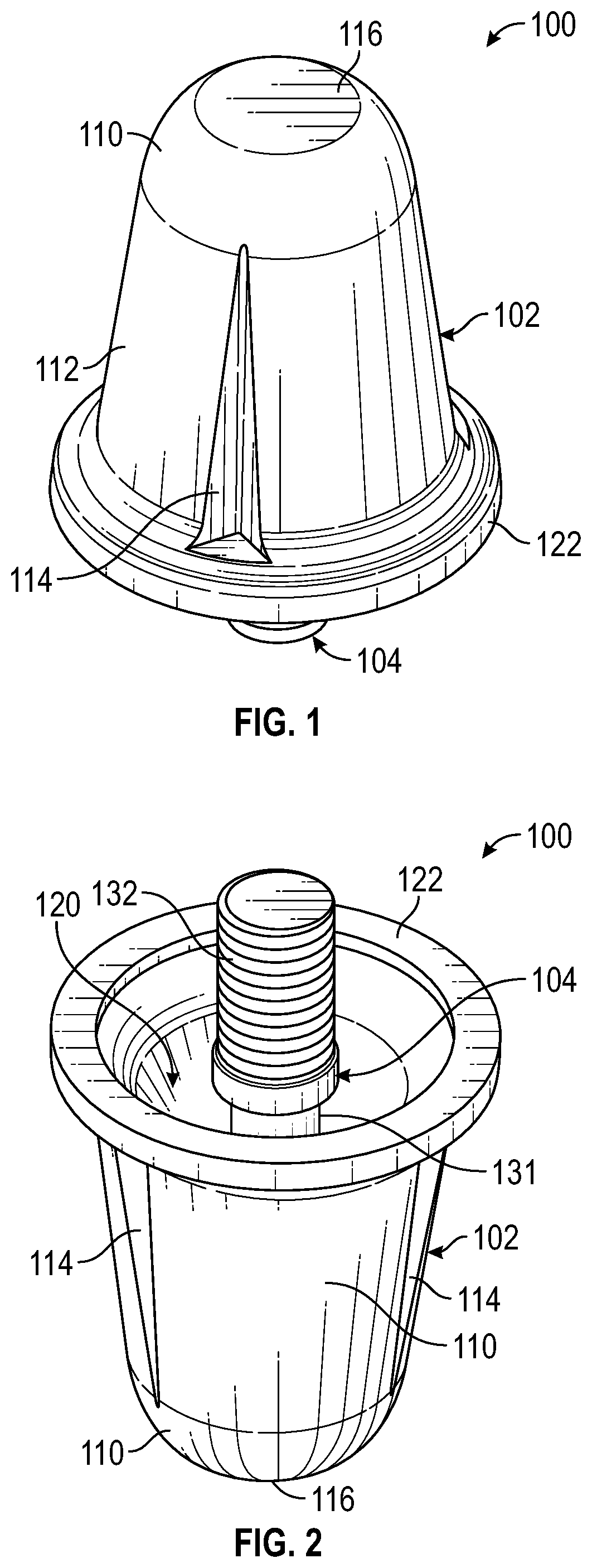
[0005] FIG. 1 is a top perspective view of a first embodiment of a traction element showing the stud body and metal insert;
[0006] FIG. 2 is a rear perspective view of the traction element of FIG. 1 showing the metal insert extending from the interior cavity of the stud body;
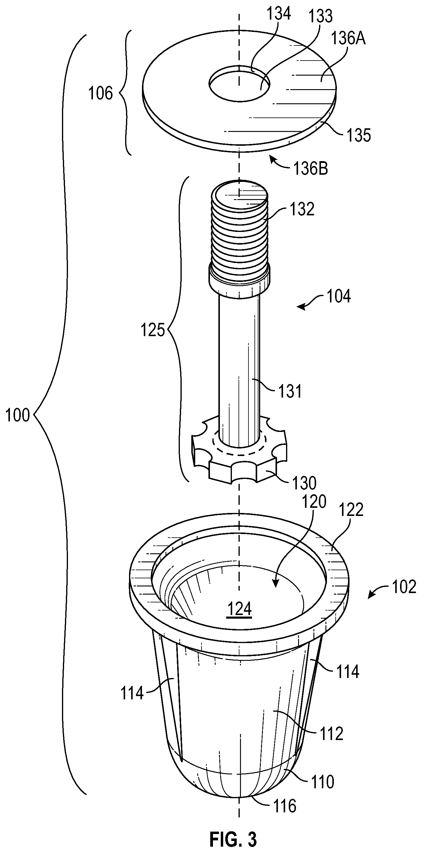
[0007] FIG. 3 is an exploded view of the traction element of FIG. 1;
[0008] FIG. 4 is a side view of the traction element of FIG. 1;
[0009] FIG. 5 is a top view of the traction element of FIG. 1;
[0010] FIG. 6 is a bottom view of the traction element of FIG. 1; and
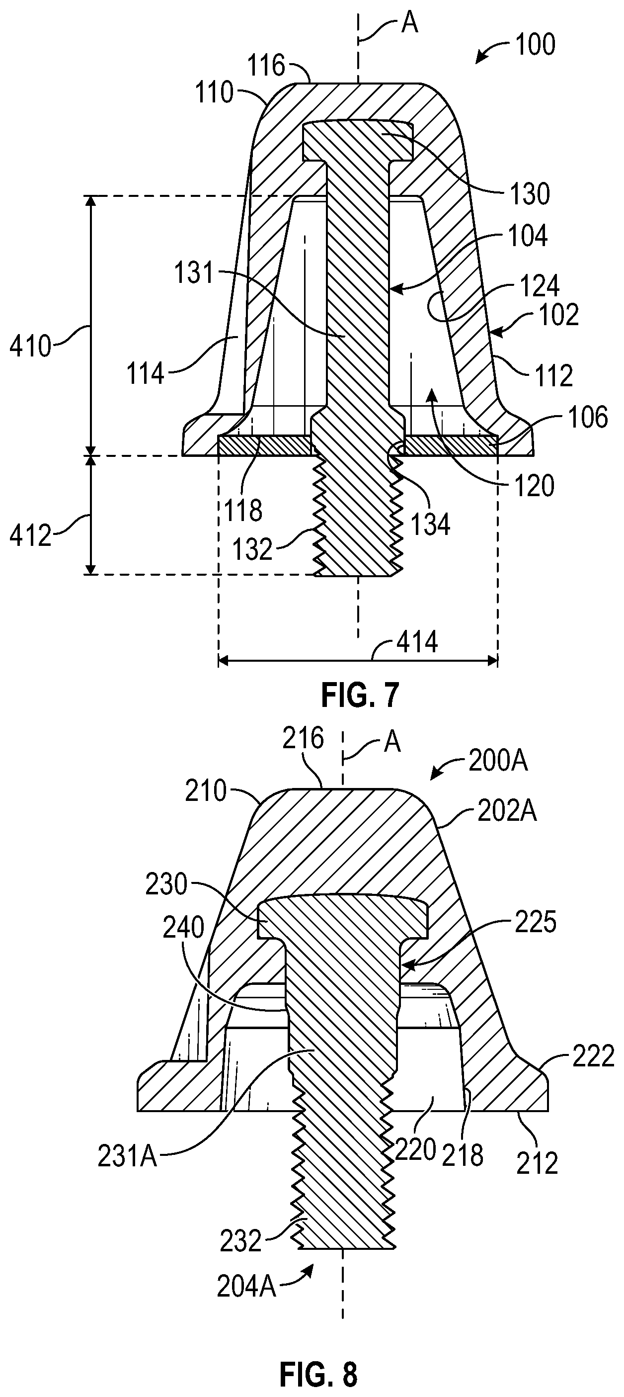
[0011] FIG. 7 is a cross-sectional view of the traction element taken along line 7-7 of FIG. 5;
[0012] FIG. 8 is a cross-sectional view of a second traction element showing a metal insert engaged within an interior cavity of a stud body;
[0013] FIG. 9 is a side view of the metal insert of FIG. 8;
[0014] FIGS. 10A and 10B are perspective views of the metal insert of FIG. 8;
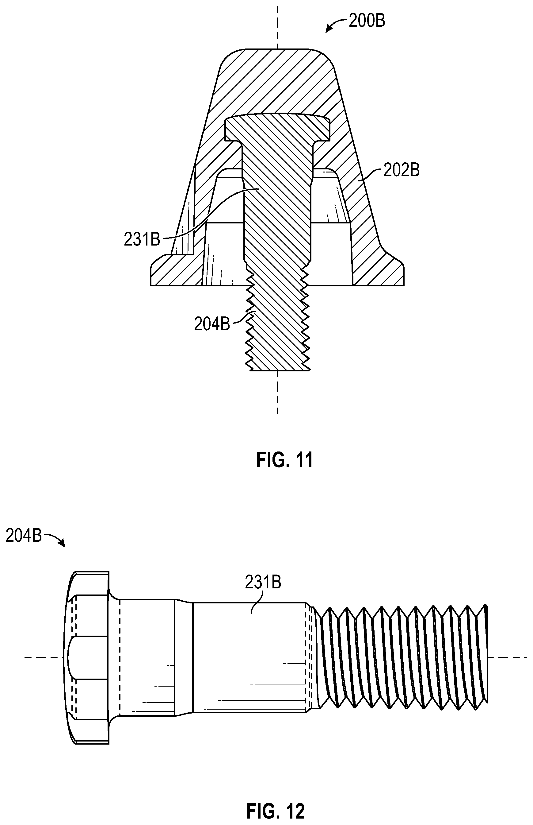
[0015] FIG. 11 is a cross-sectional view of a second traction element showing a metal insert engaged within an interior cavity of a stud body;
[0016] FIG. 12 is a side view of the metal insert of FIG. 11;
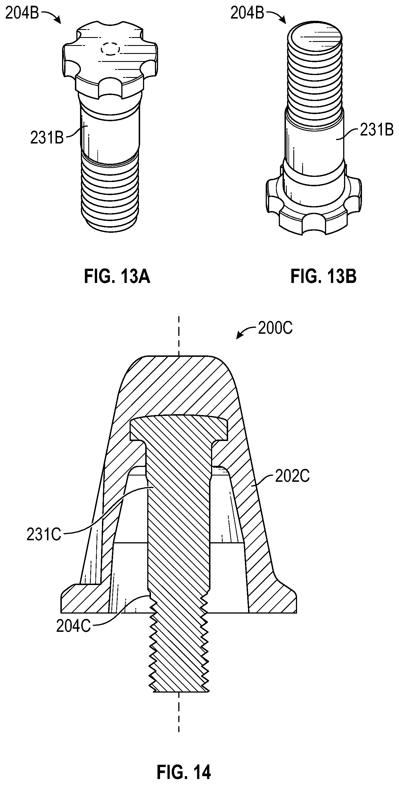
[0017] FIGS. 13A and 13B are perspective views of the metal insert of FIG. 11;
[0018] FIG. 14 is a cross-sectional view of a second traction element showing a metal insert engaged within an interior cavity of a stud body;
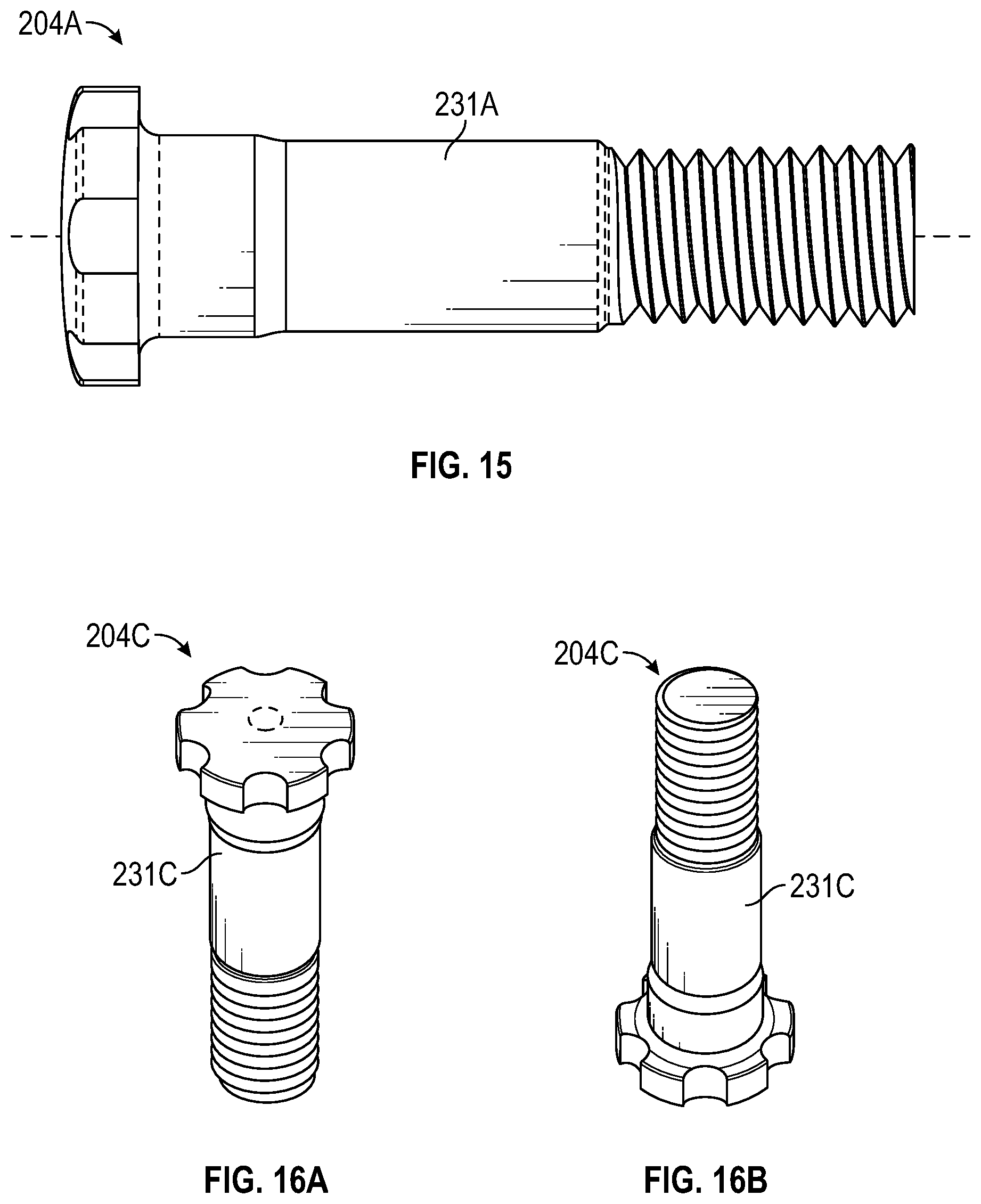
[0019] FIG. 15 is a side view of the metal insert of FIG. 14; and
[0020] FIGS. 16A and 16B are perspective views of the metal insert of FIG. 14.
[0021] Corresponding reference characters indicate corresponding elements among the view of the drawings. The headings used in the figures do not limit the scope of the claims.
DETAILED DESCRIPTION
[0022] Various embodiments for traction elements used for athletic shoes are disclosed herein. In some embodiments, the traction elements have reduced weight while still meeting existing industry performance standards for athletic shoes. In some embodiments, the traction element includes a stud body defining an interior cavity with a metal insert that is cast to the stud body and extends outwardly from the interior cavity and a stabilizer disc engaged with the metal insert and within the internal cavity. In some embodiments, the traction element includes a stud body defining an interior cavity and a metal insert that is mechanically coupled within the stud body and extends outwardly from the interior cavity. In some embodiments, the metal insert of the traction element is configured to be coupled to the sole of an athletic shoe for providing traction. In some embodiments, the stabilizer disc is provided that is engaged within the interior cavity of the stud body and the metal insert such that the metal insert is stabilized against laterally directed forces by the stabilizer disc. In some embodiments, a method of manufacturing the traction element such that the metal insert is either cast to the stud body or mechanically coupled to the stud body prior to being engaged to the sole of an athletic shoe is disclosed. In one aspect, the traction element meets the current standards required of official governing sports bodies, such as the ROC, which governs international rugby regarding the performance, shape and material requirements set for athletic equipment, such as rugby studs used in athletic shoes including the traction element described herein. Referring to the drawings, various embodiments of a traction element used with athletic shoes are illustrated and generally indicated as 100 in FIGS. 1-7 and 200 in FIGS. 8-16.
[0023] Referring to FIGS. 1-7, a first embodiment of the traction element, designed 100, is illustrated. In some embodiments, the traction element 100 includes a stud body 102 having a generally thimble-shaped body configured to provide traction and gripping strength along a ground surface when attached to the sole of an athletic shoe. In some embodiments, the stud body 102 includes a metal insert 104 that is cast to the stud body 102 during manufacture and is aligned along the longitudinal axis A of the stud body 102. The metal insert 104 is configured to mechanically couple the traction element 100 to the sole of an athletic shoe (not shown). The traction element 100 further includes a stabilizer disc 106 for engagement with the stud body 102 and the metal insert 104 to provide stability to the metal insert 104 within the stud body 102. Referring specifically to FIGS. 2-4 and 6 and 7, the stud body 102 defines a distal head portion 110 and a proximal end portion 112. In some embodiments, the proximal end portion 112 of the stud body 102 gradually tapers away from the distal head portion 110 and forms a peripheral flange 122 that defines an opening 118 in communication with an interior cavity 120 formed within the stud body 102 during manufacture. As further shown, the distal head portion 110 defines a top end 116 of the traction element 100 that is configured to provide a traction surface along the sole of an athletic shoe (not shown) when the traction element 100 engages the ground or other athletic surface.
[0024] Referring to FIG. 7, in some embodiments the metal insert 104 is made of steel and/or aluminum that forms an elongated body 125 defining a distal head portion 130, which is cast to the stud body 102 during manufacture. In addition, the distal head portion 130 communicates with a shaft portion 131 of the metal insert 104 that extends between the distal cap portion 130 and a proximal threaded portion 132 of the metal insert 104. As shown, the proximal threaded portion 130 defines external threads 135 configured to couple with internal threads (not shown) formed within each respective threaded engagement point defined along the sole of an athletic shoe (not shown).
[0025] In some embodiments shown in FIGS. 3 and 7, the stabilizer disc 106 may be made of steel and/or aluminum that forms a first surface 136A, a second surface 136B, an exterior surface 135, and an internal surface 134 which circumferentially defines an aperture 133. The stabilizer disc 106 is configured to provide stability to the metal insert 104 within the interior cavity 120 of the stud body 102 when engaged with the metal insert 104 and pressed into opening 118 of the stud body 102. During manufacture, the stabilizer disc 106 is engaged with the shaft portion 131 of the metal insert 104 by inserting the stabilizer disc 106 within the opening 118 of the stud body 102 such that the proximal threaded portion 132 of the metal insert 104 is inserted through the aperture 133. The stabilizer disc 106 becomes engaged within the interior cavity 120 of the stud body 102 by inserting the proximal threaded portion 132 of the metal insert 104 through the aperture 133 of the stabilizer disc 106 such that the stabilizer disc 106 is pushed into the opening 118 of the stud body 102 causing the exterior surface 135 of the stabilizer disc 106 to contact the surface of the interior cavity 120 in a press-fit engagement. When fully engaged, the aperture 133 of the stabilizer disc 106 is located distal to the proximal threaded portion 132 of the shaft portion 131 of the metal insert 104 and the exterior surface 135 comes into contact with the surface of the interior cavity 120 of the stud body 102 and is held in place by friction. In operation, the stabilizer disc 106 serves to prevent the metal insert 104 from bending or becoming otherwise misaligned within the interior cavity 120 of the stud body 102, especially when exterior forces are applied to the stud body 102.
[0026] As shown specifically in FIGS. 4 and 5, in some embodiments a plurality of cutaways 114 may be formed axially along the outer surface of the stud body 102. The plurality of cutaways 114 may be collectively configured to receive a driving tool (not shown), such as a cleat wrench, that engages each respective cutaway 114 such that rotation of the cleat wrench causes the stud body 102 to be manually rotated as the metal insert 104 becomes fully engaged to the threaded engagement point along the sole of the athletic shoe. Referring specifically to FIG. 5, in some embodiments the stud body 102 may define three respective cutaways, 114A, 114B and 114C that each extend a distance axially along the surface of proximal end portion 112 of the stud body 102 and are spaced equidistantly relative to each other at a 120 degree angle. In other embodiments, two or more cutaways 114 may be formed to engage the cleat wrench when securing the traction element 100 to the sole of the athletic shoe. In some embodiments, each cutaway 114 forms an elongated slot configuration forming a base proximate the peripheral flange 122 of the stud body 102 that extends the length of the proximal end portion 112 and gradually tapers to an apex formed at the top of each cutaway 114. In other embodiments, the plurality of cutaways 114 may define a triangularly-shaped slot, a rectangular-shaped slot, a symmetrically-shaped slot, an asymmetrically-shaped slot, a circular-shaped slot, or a combination thereof.
[0027] In one method of manufacturing the traction element 100, the stud body 102 may be first cast from a metallic material, such as aluminum, in which the metal insert 104 is directly cast to the stud body 102 such that the proximal threaded portion 132 of the metal insert 104 extends partially outward from the cast of the stud body 102. The interior cavity 120 is formed inside the stud body 102 by coring out the interior portion of the stud body 102 around the metal insert 104 to form the interior cavity 120 and opening 118. In some embodiments, the plurality of cutaways 114 are formed when the stud body 102 is cast within a mold, or in the alterative, the plurality of cutaways 114 may be machined out along the surface of the proximal end portion 112 after the cast of the stud body 102 is allowed to sufficiently cool. The method of manufacturing the traction element 100 as disclosed herein provides a strong structural connection between the stud body 102 and the metal insert 104 such that shear forces applied to the traction element 100 during use do not cause the metal insert 104 to break, bend or twist relative to the stud body 102.
[0028] In one aspect, the coring out of stud body 102 to form the interior cavity 120 during manufacture reduces the overall weight of the traction element 100 while still allowing the traction element 100 to meet all performance, shape specifications and material requirements required of a conventional traction element.
[0029] In some embodiments, the traction element 100 may be manufactured with the following dimensions used during manufacture. Referring to FIG. 4, the stud body 102 may have an overall length 400 of 20.8 mm and a width 402 of 19.4 mm. As further shown, the distal head portion 110 of the stud body 102 may have a width 404 of 11.9 mm and a length 406 of 4 mm, while the proximal end portion 112 of the stud body 102 may have a length 408 of 16.8 mm and a width 402 of 20.8 mm. Referring back to FIG. 7, the interior cavity 120 of the stud body 102 may have a length 410 of 14.6 mm and the opening 118 of the interior cavity 120 may have a length 414 of 9.0 mm. After the metal insert 104 is cast with the stud body 102, the proximal threaded portion 132 of the metal insert 104 is centered along the longitudinal axis A of the stud body 102 and extends outwardly from the opening 118 of the stud body 102 at a distance 412 of 6.0 mm. The present disclosure contemplates that the dimensions of the stud body 102 and the metal insert 104 may vary to accommodate different shapes and sizes of traction elements used for different types of athletic shoes.
[0030] Referring to FIGS. 8-16, a traction element 200 is illustrated having a variety of lengths. In particular, FIGS. 8-10 show traction element 200A having a length of 15 mm, FIGS. 11-13B show traction element 200B having a length of 18 mm, and FIGS. 14-16B show traction element 200C having a length of 21 mm, however the traction element 100/200 is not limited to these lengths. Referring to FIG. 8, in some embodiments, the traction element 200A includes a stud body 202A having a generally thimble-shaped body configured to provide traction and gripping strength along a ground surface when attached to the sole of an athletic shoe. In some embodiments, the stud body 202A is engaged with a metal insert 204A that is aligned along the longitudinal axis A of the stud body 202A. The metal insert 204A is configured to mechanically couple the traction element 200A to the sole of an athletic shoe (not shown). The stud body 202A defines a distal head portion 210 and a proximal end portion 212. In some embodiments, the proximal end portion 212 of the stud body 202A gradually tapers away from the distal head portion 210 and forms a peripheral flange 222 that defines an opening 218 in communication with an interior cavity 220 formed within the stud body 202A during manufacture. As further shown, the distal head portion 210 defines a top end 216 of the traction element 200 that is configured to provide a traction surface along the sole of an athletic shoe (not shown) when the traction element 100 engages the ground or other athletic surface.
[0031] Referring to FIGS. 8-10, in some embodiments the metal insert 204A is made of steel and/or aluminum that forms an elongated body 225 defining a distal head portion 230 and a proximal threaded portion 232. In addition, the distal head portion 230 communicates with a shaft portion 231A of the metal insert 204A that extends between the distal head portion 230 and the proximal threaded portion 232 of the metal insert 204A. As shown, the metal insert 204A includes a shoulder 240 which is seated within the stud body 202A of the traction element 200A. As shown, the proximal threaded portion 232 defines external threads 235 configured to couple with internal threads (not shown) formed within each respective threaded engagement point defined along the sole of an athletic shoe (not shown). The distal head portion 230 includes a plurality of ridges 242 to prevent rotation of the metal insert 204A within the stud body 202A.
[0032] Similarly, FIGS. 11 and 14 show respective traction elements 200B and 200C having elongated stud bodies 202A and 202B. As shown in FIGS. 11-12B, the traction element 200B is similar to traction element 200A (FIG. 8) with the exception that the stud body 202B is lengthened in comparison to the stud body 202A. In addition, a metal insert 204B having an elongated shaft portion 231B of is also lengthened in comparison to the shaft portion 231A of traction element 204A.
[0033] FIGS. 14-16 also illustrate the traction element 200C having an elongated stud body 202C and a metal insert 204C having an elongated shaft portion 231C. The stud body 202C and shaft portion 231C of the traction element 200C are lengthened in comparison to that of the traction elements 200A and 200B.
[0034] Overall, the traction elements 100 and 200 have been shown in to provide a 20% weight savings over the same class of traditional traction elements, such as rugby studs. In addition, the traction elements 100 and 200 meet or exceed all IRB specifications required for official approval and qualification for use in events while weighing 20% less than traditional traction elements.
[0035] The manufacturing of the traction elements 100 and 200 in the correct shape and materials have been made for over 50 years with the same approach and same resulting weight. The traction elements 100 and 200 meet all of the IRB requirement of shape, materials, strength, design, and delivers everything at 20% less weight. These characteristics of traction elements 100 and 200 provide performance benefits for the athletes by having lighter weight athletic having the traction elements 100 and 200.
[0036] It should be understood from the foregoing that, while particular embodiments have been illustrated and described, various modifications can be made thereto without departing from the spirit and scope of the invention as will be apparent to those skilled in the art. Such changes and modifications are within the scope and teachings of this invention as defined in the claims appended hereto.
* * * * *
D00000
D00001
D00002
D00003
D00004
D00005
D00006
D00007
D00008
XML
uspto.report is an independent third-party trademark research tool that is not affiliated, endorsed, or sponsored by the United States Patent and Trademark Office (USPTO) or any other governmental organization. The information provided by uspto.report is based on publicly available data at the time of writing and is intended for informational purposes only.
While we strive to provide accurate and up-to-date information, we do not guarantee the accuracy, completeness, reliability, or suitability of the information displayed on this site. The use of this site is at your own risk. Any reliance you place on such information is therefore strictly at your own risk.
All official trademark data, including owner information, should be verified by visiting the official USPTO website at www.uspto.gov. This site is not intended to replace professional legal advice and should not be used as a substitute for consulting with a legal professional who is knowledgeable about trademark law.