Sole Structure Of An Article Of Footwear
Cross; Tory M.
U.S. patent application number 16/833617 was filed with the patent office on 2020-10-01 for sole structure of an article of footwear. This patent application is currently assigned to NIKE, Inc.. The applicant listed for this patent is NIKE, Inc.. Invention is credited to Tory M. Cross.
| Application Number | 20200305544 16/833617 |
| Document ID | / |
| Family ID | 1000004762246 |
| Filed Date | 2020-10-01 |


View All Diagrams
| United States Patent Application | 20200305544 |
| Kind Code | A1 |
| Cross; Tory M. | October 1, 2020 |
SOLE STRUCTURE OF AN ARTICLE OF FOOTWEAR
Abstract
A sole structure includes a mid-foot region, a heel region, a lateral side and a medial side is provided. The sole structure has a first sole element including a first inner surface having a plurality of first surface features, whereby at least one of the first surface features has a different configuration than another one of the first surface features. The sole structure further includes a second sole element including a second inner surface having a plurality of second surface features configured to interface with the first surface features. A panel is disposed between the first sole element and the second sole element, such that the sole element is disposed on a first side of the panel and the second sole element being disposed on a second side of the panel, opposite the first side.
| Inventors: | Cross; Tory M.; (Portland, OR) | ||||||||||
| Applicant: |
|
||||||||||
|---|---|---|---|---|---|---|---|---|---|---|---|
| Assignee: | NIKE, Inc. Beaverton OR |
||||||||||
| Family ID: | 1000004762246 | ||||||||||
| Appl. No.: | 16/833617 | ||||||||||
| Filed: | March 29, 2020 |
Related U.S. Patent Documents
| Application Number | Filing Date | Patent Number | ||
|---|---|---|---|---|
| 62825898 | Mar 29, 2019 | |||
| Current U.S. Class: | 1/1 |
| Current CPC Class: | A43B 13/14 20130101 |
| International Class: | A43B 13/14 20060101 A43B013/14 |
Claims
1. A sole structure having a forefoot region, a mid-foot region, a heel region, a lateral side and a medial side, the sole structure comprising: a first sole element including a first inner surface having a plurality of first surface features, at least one of the first surface features having a different configuration than another one of the first surface features; a second sole element including a second inner surface having a plurality of second surface features configured to interface with the first surface features; and a panel disposed between the first sole element and the second sole element, the first sole element being disposed on a first side of the panel and the second sole element being disposed on a second side of the panel, opposite the first side.
2. The sole structure of claim 1, wherein the first surface features include a plurality of protrusions and the second surface features include a plurality of depressions configured to mate with the protrusions.
3. The sole structure of claim 1, wherein the first surface features include at least one first protrusion having a first configuration and at least one second protrusion having a second configuration different than the first configuration, the second surface features including at least one first depression having the first configuration and at least one second depression having the second configuration.
4. The sole structure of claim 3, wherein the first configuration includes at least one of a first size, a first shape, and a first orientation, and the second configuration includes at least one of a second size, a second shape, and a second orientation.
5. The sole structure of claim 3, wherein the at least one first protrusion and the at least one second protrusion respectively oppose the at least one first depression and the at least one second depression.
6. The sole structure of claim 1, wherein the first surface features includes a first plurality of ribs having a first configuration and a second plurality of ribs having a second configuration different from the first configuration.
7. The sole structure of claim 6, wherein each of the ribs extends from a first end to a second end.
8. The sole structure of claim 7, wherein a width of each of the ribs tapers along a direction from the first end to the second end.
9. The sole structure of claim 6, wherein a spacing between adjacent ones of the ribs in the forefoot region is different from a spacing between adjacent ones of the ribs in the heel region.
10. The sole structure of claim 6, wherein ribs of the first plurality of ribs extend along a first direction and ribs of the second plurality of ribs extend along a second direction transverse to the first direction.
11. An article of footwear comprising: an upper having a bottom panel and a peripheral sidewall cooperating to define an interior void; a first sole element disposed on a first side of the bottom panel within the interior void and including a first inner surface having a plurality of first surface features opposing the bottom panel, at least one of the first surface features having a different configuration than another one of the first surface features; and a second sole element disposed on an opposite side of the bottom panel from the first sole element and including a second inner surface having a plurality of second surface features opposing the bottom panel and configured to interface with the first surface features.
12. The article of footwear of claim 11, wherein at least one of the bottom panel and the peripheral sidewall is formed of a textile.
13. The article of footwear of claim 12, wherein the bottom panel is integrally formed with the peripheral sidewall.
14. The article of footwear of claim 11, wherein the bottom panel includes an inner layer on a first side of the first sole element and an outer layer disposed on an opposite side of the first sole element from the inner layer.
15. The article of footwear of claim 11, wherein the bottom panel defines a pocket receiving the first sole element.
16. The article of footwear of claim 11, wherein the bottom panel conforms to the plurality of first surface features.
17. A method of manufacturing an article of footwear, the method comprising: forming a first sole element including a first inner surface having a plurality of first surface features, at least one of the first surface features having a different configuration than another one of the first surface features; forming a second sole element including a second inner surface having a plurality of second surface features configured to interface with the first surface features; and disposing a panel between the first inner surface of the first sole element and the second inner surface of the second sole element.
18. The method of claim 17, further comprising defining at least one channel extending from a first end at a peripheral side surface of the first sole element to a second end at the peripheral side surface of the first sole element.
19. The method of claim 18, further comprising positioning a cable within the at least one channel, the cable being positioned between the panel and the first sole element or between the panel and the second sole element.
20. The method of claim 17, further comprising forming the panel from a textile.
Description
CROSS REFERENCE TO RELATED APPLICATIONS
[0001] This non-provisional U.S. patent application claims priority under 35 U.S.C. .sctn. 119(e) to U.S. Provisional Patent Application Ser. No. 62/825,898, filed Mar. 29, 2019, the disclosure of which is hereby incorporated by reference in its entirety.
FIELD
[0002] The present disclosure relates generally to an article of footwear and more particularly to a sole structure for an article of footwear.
BACKGROUND
[0003] This section provides background information related to the present disclosure and is not necessarily prior art.
[0004] Articles of footwear conventionally include an upper and a sole structure. The upper may be formed from any suitable material(s) to receive, secure, and support a foot on the sole structure. The upper may cooperate with laces, straps, or other fasteners to adjust the fit of the upper around the foot. A bottom portion of the upper, proximate to a bottom surface of the foot, attaches to the sole structure.
[0005] Sole structures generally include a stacked arrangement of a midsole and an outsole extending between a ground surface and the upper. The outsole provides abrasion-resistance and traction with the ground surface and may be formed from rubber or other materials that impart durability and wear-resistance, as well as enhancing traction with the ground surface. The midsole is disposed between the outsole and the upper. While existing sole structures perform adequately for their intended purpose, improvements to sole structures are continuously being sought in order to advance the arts.
DESCRIPTION OF THE DRAWINGS
[0006] The drawings described herein are for illustrative purposes only of selected embodiments and not all possible implementations, and are not intended to limit the scope of the present disclosure.
[0007] FIG. 1 is a lateral-side elevation view of an article of footwear in accordance with the principles of the present disclosure;
[0008] FIG. 2 is an exploded perspective view of the article of footwear of FIG. 1;
[0009] FIG. 3 is a partially exploded perspective view of the article of footwear of FIG. 1;
[0010] FIG. 4 is a perspective view of an inner sole element of the article of footwear of FIG. 1;
[0011] FIG. 5 is a perspective view of an outer sole element of the article of footwear of FIG. 1;
[0012] FIG. 6 is a plan view of the inner sole element of FIG. 4;
[0013] FIG. 7 is a plan view of the outer sole element of FIG. 5;
[0014] FIG. 8 is a lateral-side elevation view of an article of footwear in accordance with the principles of the present disclosure;
[0015] FIG. 9 is an exploded perspective view of the article of footwear of FIG. 8;
[0016] FIG. 10 is a perspective view of an inner sole element of the article of footwear of FIG. 8;
[0017] FIG. 11 is a perspective view of an outer sole element of the article of footwear of FIG. 8;
[0018] FIG. 12 is a plan view of the inner sole element of FIG. 10;
[0019] FIG. 13 is a plan view of the outer sole element of FIG. 11;
[0020] FIG. 14 is a lateral-side elevation view of an article of footwear in accordance with the principles of the present disclosure;
[0021] FIG. 15 is an exploded perspective view of the article of footwear of FIG. 14;
[0022] FIG. 16 is a perspective view of an inner sole element of the article of footwear of FIG. 14;
[0023] FIG. 17 is a perspective view of an outer sole element of the article of footwear of FIG. 14;
[0024] FIG. 18 is a plan view of the inner sole element of FIG. 16;
[0025] FIG. 19 is a plan view of the outer sole element of FIG. 17;
[0026] FIG. 20 is a lateral-side elevation view of an article of footwear in accordance with the principles of the present disclosure;
[0027] FIG. 21 is an exploded perspective view of the article of footwear of FIG. 20;
[0028] FIG. 22 is a perspective view of an inner sole element of the article of footwear of FIG. 20;
[0029] FIG. 23 is a perspective view of an outer sole element of the article of footwear of FIG. 20;
[0030] FIG. 24 is a plan view of the inner sole element of FIG. 22;
[0031] FIG. 25 is a plan view of the outer sole element of FIG. 23;
[0032] FIG. 26 is a lateral-side elevation view of an article of footwear in accordance with the principles of the present disclosure;
[0033] FIG. 27 is an exploded perspective view of the article of footwear of FIG. 8;
[0034] FIG. 28 is a perspective view of an inner sole element of the article of footwear of FIG. 8;
[0035] FIG. 29 is a perspective view of an outer sole element of the article of footwear of FIG. 8;
[0036] FIG. 30 is a plan view of the inner sole element of FIG. 28; and
[0037] FIG. 31 is a plan view of the outer sole element of FIG. 29.
[0038] Corresponding reference numerals indicate corresponding parts throughout the several views of the drawings.
DETAILED DESCRIPTION
[0039] The present disclosure is directed to sole structures, articles of footwear including the sole structures, methods of manufacturing the sole structures, sole structures manufactured using the methods, methods of manufacturing articles of footwear including the sole structures, and articles of footwear manufactured using the methods. These sole structures provide cushioning as well as lateral stability for articles of footwear. The sole structure has a forefoot region, a mid-foot region, a heel region, a lateral side and a medial side, and includes a first sole element including a first inner surface having a plurality of first surface features, at least one of the first surface features having a different configuration than another one of the first surface features; a second sole element including a second inner surface having a plurality of second surface features configured to interface with the first surface features; and a panel disposed between the first sole element and the second sole element, the first sole element being disposed on a first side of the panel and the second sole element being disposed on a second side of the panel, opposite the first side. The first surface features, or the second surface features, or both can include at least one rib. In some examples, the rib defines one or more channels, and at least one cable can extend through a channel. These cables can be used to provide lock-down of the upper to the sole structure during wear. The panel can comprise a film or sheet of material, or can comprise textile, such as a knitted textile, a woven textile, a braided textile, a crocheted textile, or a non-woven textile. As the properties of the panel affect the lateral stability of sole structure, in a manufacturing setting, the properties of the sole structure can be easily varied by varying the type of panel used in the sole structure. In particular examples, the panel can be integrally formed with the upper for the article of footwear, such that the step of disposing the panel between the first sole element and the second sole element also serves to affix the upper to the sole structure, thereby providing a simpler manufacturing process which is amenable to being automated.
[0040] Example embodiments will now be described more fully with reference to the accompanying drawings. Example embodiments are provided so that this disclosure will be thorough, and will fully convey the scope of those who are skilled in the art. Numerous specific details are set forth such as examples of specific components, devices, and methods, to provide a thorough understanding of embodiments of the present disclosure. It will be apparent to those skilled in the art that specific details need not be employed, that example embodiments may be embodied in many different forms and that neither should be construed to limit the scope of the disclosure. In some example embodiments, well-known processes, well-known device structures, and well known technologies are not described in detail.
[0041] The terminology used herein is for the purpose of describing particular example embodiments only and is not intended to be limiting. As used herein, the singular forms "a," "an," and "the" may be intended to include the plural forms as well, unless the context clearly indicates otherwise. The terms "comprises," "comprising," "including," and "having," are inclusive and therefore specify the presence of modified features, integers, steps, operations, elements, and/or components, but do not preclude the presence or addition of one or more other features, integers, steps, operations, elements, components, and/or groups thereof. The method steps, processes, and operations described herein are not to be construed as necessarily requiring their performance in the particular order discussed or illustrated, unless specifically identified as an order of performance. It is also to be understood that additional or alternative steps may be employed.
[0042] When an element or sheet is referred to as being "on," "engaged to," "connected to," or "coupled to" another element or sheet, it may be directly on, engaged, connected or coupled to the other element or sheet, or intervening elements or sheets may be present. In contrast, when an element is referred to as being "directly on," "directly engaged to," "directly connected to," or "directly coupled to" another element or sheet, there may be no intervening elements or sheets present. Other words used to describe the relationship between elements should be interpreted in a like fashion (e.g., "between" versus "directly between," "adjacent" versus "directly adjacent," etc.). As used herein, the term "and/or" includes any and all combinations of one or more of the associated listed items.
[0043] Although the terms first, second, third, etc. may be used herein to describe various elements, components, regions, sheets and/or sections, these elements, components, regions, sheets and/or sections should not be limited by these terms. These terms may be only used to distinguish one element, component, region, sheet or section from another region, sheet or section. Terms such as "first," "second," and other numerical terms when used herein do not imply a sequence or order unless clearly indicated by the context. Thus, a first element, component, region, sheet or section discussed below could be termed a second element, component, region, sheet or section without departing from the teachings of the example embodiments.
[0044] Spatially relative terms, such as "inner," "outer," "beneath," "below," "lower," "above," "upper," and the like, may be used herein for ease of description to describe one element or feature's relationship to another element(s) or feature(s) as illustrated in the figures. Spatially relative terms may be intended to encompass different orientations of the device in use or operation in addition to the orientation depicted in the figures. For example, if the device in the figures is turned over, elements described as "below" or "beneath" other elements or features would then be oriented "above" the other elements or features. Thus, the example term "below" can encompass both an orientation of above and below. The device may be otherwise oriented (rotated 90 degrees or at other orientations) and the spatially relative descriptors used herein interpreted accordingly.
[0045] With reference to the figures, a sole structure having a forefoot region, a mid-foot region, a heel region, a lateral side and a medial side is provided. The sole structure includes a first sole element including a first inner surface having a plurality of first surface features, at least one of the first surface features having a different configuration than another one of the first surface features. The sole structure further includes a second sole element including a second inner surface having a plurality of second surface features configured to interface with the first surface features, and a panel disposed between the first sole element and the second sole element, the first sole element being disposed on a first side of the panel and the second sole element being disposed on a second side of the panel, opposite the first side.
[0046] Implementations of the disclosure may include one of more of the following optional features. In some examples, the first surface features include a plurality of protrusions and the second surface features include a plurality of depressions configured to mate with the protrusions.
[0047] In some implementations, the first surface features include at least one first protrusion having a first configuration and at least one second protrusion having a second configuration different than the first configuration, the second surface features including at least one first depression having the first configuration and at least one second depression having the second configuration. Here, the first configuration may include at least one of a first size, a first shape, and a first orientation, and the second configuration includes at least one of a second size, a second shape, and a second orientation. Optionally, the at least one first protrusion and the at least one second protrusion respectively oppose the at least one first depression and the at least one second depression.
[0048] In some examples, the first surface features includes a first plurality of ribs having a first configuration and a second plurality of ribs having a second configuration different from the first configuration. Optionally, each of the ribs extends from a first end to a second end. Here, a width of each of the ribs may along a direction from the first end to the second end. Optionally, a spacing between adjacent ones of the ribs in the forefoot region is different from spacing between adjacent ones of the ribs in the heel region. In some examples, the first plurality of the ribs extend along a first direction and the second plurality of the ribs extend along a second direction transverse to the first direction.
[0049] In some implementations, the surface features include a first protrusion disposed within in the forefoot region, a second protrusion disposed within the heel region, a plurality of first ribs partially surrounding the first protrusion, a plurality of second ribs completely surrounding the second protrusion, and a plurality of third ribs extending between the first ribs and the second ribs.
[0050] In some examples the first ribs, the second ribs, and the third ribs are ridge-shaped. Optionally, the first ribs may extend around the first protrusion from a first end on the lateral side of the first sole element to a second end on the lateral side of the first sole element. Here, the first ribs may extend along an arcuate path and are concentric with each other and the first protrusion. In some implementations, the second ribs each extend along a circular path and are concentric with each other and the second protrusion. Optionally, the third ribs extend from a first end on the lateral side of the first sole element to a second end on the medial side of the first sole element. Each of the third ribs may extend along an arcuate path.
[0051] In some examples, the plurality of first ribs define a plurality of first channels each extending from a first end on the lateral side of the first sole element to a second end on the lateral side of the first sole element. Here, the sole structure may include at least one cable extending through at least one of the first channels.
[0052] In some examples, the plurality of second ribs define a plurality of second channels each extending from a first end on the lateral side of the first sole element to a second end on the medial side of the first sole element. Here, the sole structure may further comprise at least one cable extending through at least one of the second channels.
[0053] In some implementations the first protrusion is cylindrical. In some examples, the second protrusion is cylindrical. Optionally, the first protrusion is offset to the lateral side of the first sole element. Optionally, the second protrusion is centrally disposed between the lateral side of the first sole element and the medial side of the first sole element.
[0054] In some examples, the first protrusion has a different hardness than the second protrusion.
[0055] In another aspect of the disclosure, the first surface features include a first protrusion disposed in the forefoot region a plurality of arcuate first ribs partially surrounding the first protrusion, and a plurality of elongate second ribs disposed adjacent to the plurality of the first ribs.
[0056] Optionally, the first ribs and the second ribs are ridge-shaped. Here, the first ribs may extend around the first protrusion from a first end on the medial side of the first sole element to a second end on the medial side of the first sole element. Optionally, the first ribs extend along an arcuate path and are concentric with each other and the first protrusion. In some examples, the second ribs extend from a first end on the lateral side of the first sole element to a second end on the medial side of the first sole element. In some implementations, the second ribs extend along an arcuate path and are concentric with each other and the first protrusion. In some configurations, the first ribs and the second ribs are arranged in series from the first protrusion to a posterior end of the first sole element and progressively increase in size along a radial direction away from the first protrusion. Optionally, the first protrusion is cylindrical. In some examples, the first protrusion is disposed adjacent to the medial side of the first sole element. In some implementations, the first ribs and the second ribs are ridge-shaped.
[0057] In some configurations, the first surface features include a plurality of annular first ribs disposed in the heel region, a plurality of elongate second ribs disposed in the mid-foot region and the forefoot region. Optionally, the first ribs are concentric with each other. In some implementations, the second ribs extend from a first end on the lateral side of the first sole element to a second end on the medial side of the first sole element. In some implementations, the second ribs each extend along an arcuate path. In some examples, the second ribs are concentric with each other. In some examples, the second ribs are concentric with the first ribs.
[0058] Optionally, the second ribs are arranged in series between the first ribs and an anterior end of the first sole element. Here, the second ribs progressively change in size along a direction from the first ribs to the anterior end. In some implementations, the second ribs progressively increase in width along a direction from the first ribs to the anterior end.
[0059] In some implementations, the first ribs and the second ribs are ridge-shaped.
[0060] In another aspect of the disclosure, the first surface features include a plurality of first ribs extending radially outwardly from a central portion of the heel region, a plurality of second ribs serially arranged between the first ribs and an anterior end of the first sole element. Here, the first ribs and the second ribs may cooperate to form a nautilus pattern.
[0061] In some example, the central portion is substantially planar and peaks of the first ribs are coplanar with the central portion. Here, the first ribs may extend from first ends at the central portion to second ends at a peripheral sidewall of the first sole element. In some implementations, the first ribs each increase in height from the first end to the second end.
[0062] In some examples, the second ribs are arranged in series from the first ribs to an anterior end of the first sole element. In some implementations, the second ribs extend from a terminal first end adjacent to the medial side of the first sole element to a second end at the lateral side of the first sole element. Optionally, the second ribs each increase in height from the first end to the second end.
[0063] In some examples, the central portion is teardrop-shaped.
[0064] In some implementations, the first ribs and the second ribs are ridge-shaped.
[0065] In another aspect of the disclosure, wherein the first surface features include, a plurality of first ribs converging with each other along a first direction, and a plurality of second ribs converging with each other along a second direction. Here, the first ribs may be arranged in a first radial array and the second ribs are arranged in a second radial array. Optionally, the first ribs converge with each other in a direction from the lateral side to the medial side. In some implementations the second ribs converge with each other along a direction from the medial side to the lateral side.
[0066] In some examples, the first ribs are disposed in the forefoot region. Optionally, the second ribs are disposed in the heel region. In some implementations, the first surface features further comprise a plurality of transitional ribs disposed between the first ribs and the second ribs. In some examples, the first ribs and the second ribs are ridge-shaped. In some implementations, the first ribs each taper in width along a direction from the lateral side to the medial side. Optionally, the second ribs each taper in width along a direction from the medial side to the lateral side.
[0067] In some examples, the first sole element defines a footbed of the sole structure and the outer sole element defines a ground-engaging surface of the sole structure.
[0068] Optionally, each of the plurality of first surface features has a minimum height or depth of at least 2 mm. In some examples, each of the plurality of first surface features has a minimum height or depth of at least 11 mm. In some implementations, each of the plurality of first surface features has a maximum height or depth of less than 28 mm. In some configurations, each of the plurality of first surface features has a maximum height or depth of less than 23 mm. Optionally, the height or depth of each of the plurality of surface features ranges from about 2 mm to about 27 mm.
[0069] In some aspects, the sole structure comprises an adhesive disposed between the first sole element and the second sole element, the adhesive being applied to at least one of the first sole element, the second sole element, an upper surface of the panel, and a lower surface of the panel.
[0070] In some implementations, the panel comprises a mesh textile. In some examples, the panel is a textile configured to stretch in in only one dimension. Optionally, the panel is a textile configured to stretch in two dimensions. In some configurations, the panel is an embroidered textile.
[0071] In some examples, at least one of the first sole element and the second sole element is formed of a polymeric material having a foam structure. Here, the polymeric material having a foam structure may be an injection-molded foam. Optionally, the polymeric material having a foam structure is a compression-molded foam. In some examples, the polymeric material having a foam structure is anisotropic.
[0072] In some configurations, the panel conforms to the shape of the first surface features and conforms to the shape of the second surface features.
[0073] Another aspect of the disclosure provides an article of footwear including any of the examples of the sole structure described in the preceding paragraphs. Here, the article of footwear includes an upper including the panel and a peripheral wall defining an interior void and a throat opening. Optionally, the first sole element is disposed within the interior void of the upper and the second sole element is disposed on an exterior of the upper. Here, the article of footwear may include at least one cable extending from the throat opening and between the first sole element and the second sole element. Optionally, the cable comprises an end defining an aperture for receiving at least one fastener of the article of footwear.
[0074] In another aspect of the disclosure, a method of providing the sole structure described above includes providing an upper for an article of footwear, and affixing the sole structure and the upper to each other to form the article of footwear.
[0075] In yet another aspect of the disclosure, an article of footwear includes an upper having a bottom panel and a peripheral sidewall cooperating to define an interior void. The article of footwear further includes a first sole element disposed on a first side of the panel within the interior void and including a first inner surface having a plurality of first surface features, at least one of the first surface features having a different configuration than another one of the first surface features. A second sole element is disposed on an opposite side of the panel from the first sole element and including a second inner surface having a plurality of second surface features configured to interface with the first surface features.
[0076] In some examples, at least one of the bottom panel and the peripheral sidewall is formed of a textile, optionally a knitted, woven, braided, crocheted, or non-woven textile, optionally a knitted textile. Optionally, the upper is a sock having the bottom panel and the peripheral sidewall integrally formed. In some implementations, the bottom panel is formed as a strobel panel. In some examples, the bottom panel includes an inner layer on a first side of the first sole element and an outer layer disposed on an opposite side of the first sole element from the inner layer. Optionally, the bottom panel defines a pocket receiving the first sole element. Here, the bottom panel may conform to the plurality of first surface features.
[0077] In another aspect of the disclosure, a method of manufacturing an article of footwear includes forming a first sole element including a first inner surface having a plurality of first surface features, at least one of the first surface features having a different configuration than another one of the first surface features. The method further includes forming a second sole element including a second inner surface having a plurality of second surface features configured to interface with the first surface features, disposing a panel between the first inner surface of the first sole element and the second inner surface of the second sole element.
[0078] In some implementations, the method includes forming the first sole element and the second sole element by injection molding. Optionally, the method includes forming the plurality of surface features to include at least one channel extending from a first end at a peripheral side surface of the first sole element to a second end at the peripheral side surface of the first sole element.
[0079] In some examples, the method includes positioning a first cable within the at least one channel. Here, the method may include positioning the first cable between the panel and the first sole element. Optionally, the method includes positioning the first cable between the panel and the second sole element. In some examples, the method includes routing the cable from the first end of the channel to the second end of the channel.
[0080] In some examples, the method includes affixing the panel to a peripheral sidewall to form an upper. Here, the method may include integrally forming the panel and the peripheral sidewall of a textile. In some implementations, the method includes attaching the panel to the peripheral sidewall using strobel construction.
[0081] In some implementations, the method includes forming the panel with an inner layer and an outer layer. Optionally, the method includes positioning the first sole element between the inner layer and the outer layer.
[0082] In some examples, the method includes forming the panel with a pocket. Here, the method includes positioning the first sole element within the pocket.
[0083] In another aspect of the disclosure, an article of footwear is produced according to any of the methods described above.
[0084] With reference to FIGS. 1-7, a first example of an article of footwear 10 constructed according to the principles of the present disclosure is shown. The article of footwear 10 includes an upper 100 and a sole structure 200. Unlike conventional articles of footwear having the entire sole structure attached to a lower exterior surface of the upper, the sole structure 200 of the illustrated example includes an inner sole element 202 disposed within the upper 100 and an outer sole element 204 attached to an exterior of the upper 100, whereby a portion of the upper 100 is interposed therebetween, as discussed in greater detail below.
[0085] The footwear 10 may include an anterior end 12 associated with a forward-most point of the footwear 10, and a posterior end 14 corresponding to a rearward-most point of the footwear 10. A longitudinal axis A.sub.F of the footwear 10 extends along a length of the footwear 10 from the anterior end 12 to the posterior end 20, and generally divides the footwear 10 into a lateral side 16 and a medial side 18, respectively corresponding with opposite sides of the footwear 10 and extending from the anterior end 12 to the posterior end 14.
[0086] The article of footwear 10 may be divided into one or more regions along the longitudinal axis A.sub.F. The regions may include a forefoot region 20, a mid-foot region 22 and a heel region 24. The forefoot region 20 may correspond with toes and joints connecting metatarsal bones with phalanx bones of a foot. The mid-foot region 22 may correspond with an arch area of the foot, and the heel region 24 may correspond with rear regions of the foot, including a calcaneus bone. The forefoot region 20 may be subdivided into a toe portion 20.sub.T corresponding with phalanges and a ball portion 20.sub.B associated with metatarsal bones of a foot.
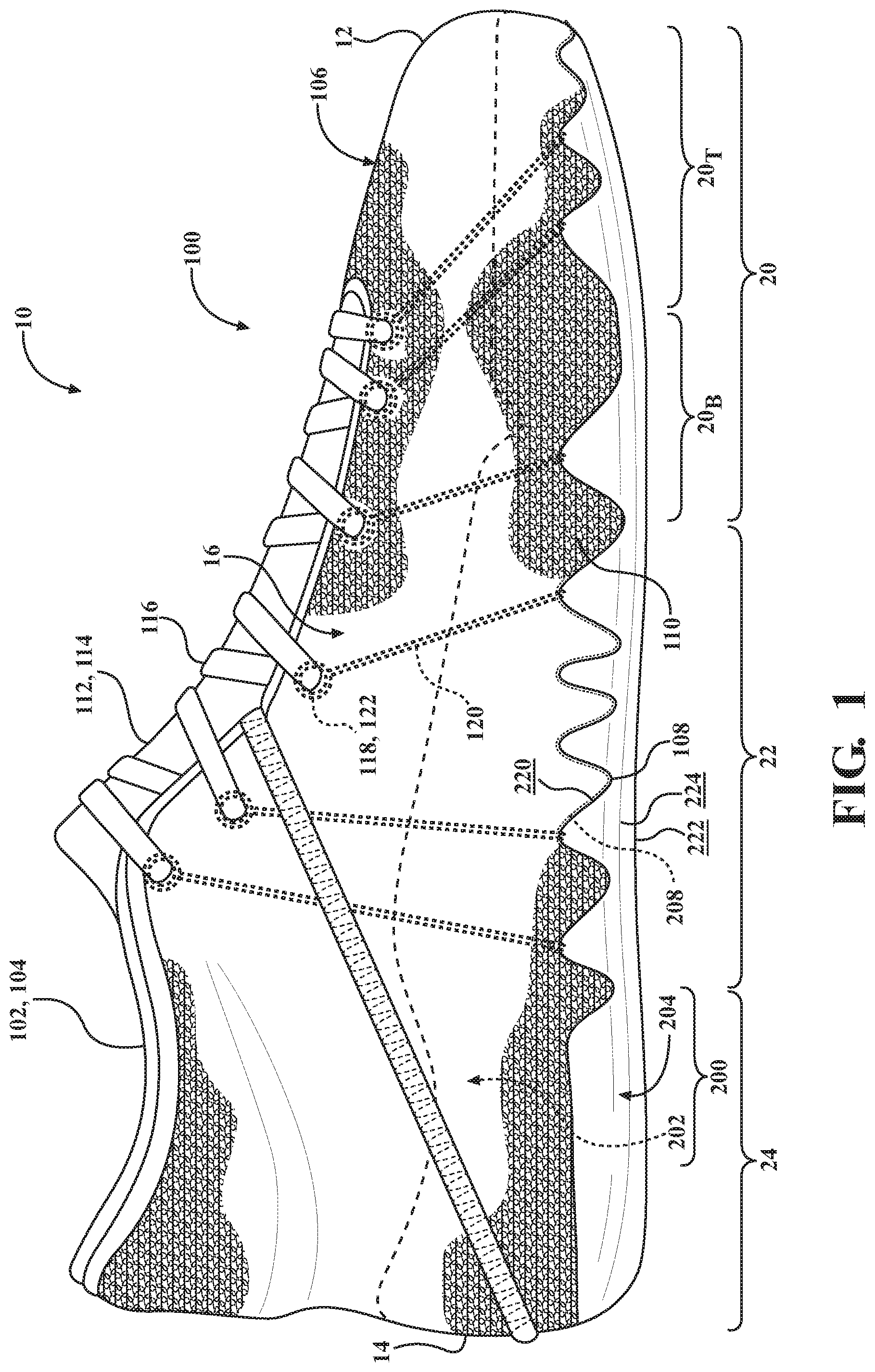
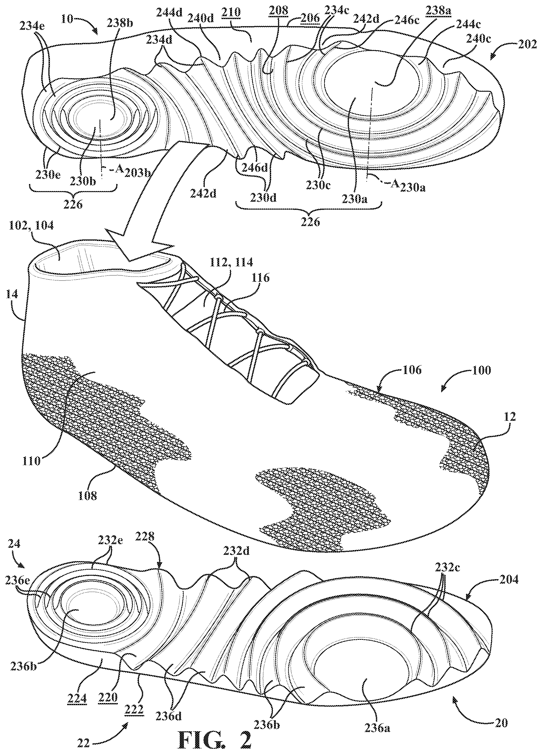
[0087] The upper 100 may be described as including a plurality of components that cooperate to define an interior void 102 and an ankle opening 104, which receive and secure a foot for support on the sole structure 200. As shown in FIG. 2, the upper 100 includes a bottom panel 108 defining a bottom of the interior void 102, and a peripheral wall 110 extending from the bottom panel 108 and surrounding the interior void 102. As discussed in greater detail below, when the footwear 10 is assembled, the bottom panel 108 will be interposed between and conform to the profiles of the inner sole element 202 and the outer sole element 204, as shown in FIG. 1.
[0088] In some examples, the upper 100 of the present disclosure includes a sock 106 formed of a single piece of a textile, such as a knitted, woven, braided, crocheted, or non-woven textile. Here, the panel 108 and the peripheral wall 110 are integrally formed in a substantially continuous sock-like structure. In other examples, the panel 108 is a strobel sock or panel formed separately from the peripheral sidewall 110, and attached to the peripheral sidewall 110 using what is commonly referred to as strobel construction, where the bottom panel 108 and the peripheral sidewall 110 are stitched together along a periphery of the bottom panel 108. Where strobel construction is used, the bottom panel 108 and the peripheral sidewall 110 may be formed of the same or different materials. Additionally or alternatively, one or both of the bottom panel 108 and the peripheral sidewall 110 may be formed of a textile, as discussed below.
[0089] In some examples, the bottom panel 108 may include an inner layer and an outer layer that cooperate to define a pocket within the bottom panel 108. The pocket 108 is configured to receive the inner sole element 202 therein, wherein the inner layer of the bottom panel 108 is disposed on a first side of the of the inner sole element 202 facing the interior void 102, and the outer layer 108 is disposed on an opposite side of the inner sole element 202, between the inner sole element 202 and the outer sole element 204.
[0090] With continued reference to the figures, the bottom panel 108 and/or the peripheral sidewall 110 may be formed from a textile. The textile can be formed by manipulating one or more fibers, filaments or yarns, using techniques such as knitting, weaving, braiding, felting, hydroentanglement, etc. Similarly, when one or more cables is included in the sole structure, the cable can be formed from one or more fibers, filaments or yarns using a knitting or braining technique. The filaments and/or fibers used to form the yarns or fibers can comprise a polymeric material such as, for example, a thermoplastic material. An exemplary thermoplastic material may include, for example, a thermoplastic polyurethane, a thermoplastic polyamide, a thermoplastic polyether, a thermoplastic polyester, a thermoplastic polyolefin, any combination thereof, or the like. In some instances, the panel is porous. In some examples, if the panel is a textile, the textile may include a polyester yarn. Furthermore, in other examples, if the panel is a textile including apertures or passages between overlapping or entangled filaments, fibers or yarns, each passage or aperture defining the structure of the textile may be at least 0.5 mm in length in a largest dimension or at least 1.0 mm in length in a largest dimension. In some instances, the panel includes an embroidered textile and has one or more first regions including embroidery and one or more second regions without embroidery or with a lower percentage of embroidered surface area as comparted to the one or more first regions. The embroidery can provide reduced stretch or a "lock down" feature to areas of the panel. In some examples, or in some portions of the upper, the panel may stretch in a single direction. In other examples, or in other portions, the panel may stretch multi-directionally.
[0091] The sock 106 of the upper 100 may include a throat opening 112 extending from the ankle opening 104 towards the forefoot region 20 between the lateral side 16 and the medial side 18 of the sock 106. A tongue 114 may be disposed within the throat opening 112 to cover the interior void 102. A plurality of fasteners 116 may extend between opposing edges of the throat opening 112 to adjust a fit of the interior void 102 around the foot and to accommodate entry and removal of the foot therefrom. The fasteners 116 may include laces, straps, cords, hook-and-loop, or any other suitable type of fastener. Accordingly, the peripheral wall 110 of the sock 106 may include a plurality of apertures 118 disposed along opposing sides of the throat opening 112, through which the fasteners 116 are routed.
[0092] In some examples, the apertures 118 may be formed through the material of the sock 106. However, in the example of the footwear 10 shown in FIGS. 1-7, at least a portion of the apertures 118 are formed at the ends of cables 120 that are integrated within the material of the sock 106. Each of the cables 120 includes at least one end 122 forming one of the apertures 118. In the illustrated example, each of the cables 120 includes a pair of ends 122 formed at opposite ends of the cable 120. As best shown in FIG. 3 and described in greater detail below, the cables 120 each extend from a first end 122 adjacent to the throat opening 112, along the peripheral wall 110 to the sole structure 200, along the bottom panel 108 between the inner sole element 202 and the outer sole element 204, and back up the peripheral wall 110 to a second end 122 adjacent to the throat opening 112. The cables 120 are formed of a material having a lower modulus of elasticity than the material forming the sock, whereby the cables 120 are configured to act as a tensile member between the sole structure 200 and the upper 100.
[0093] Referring now to FIG. 2, the sole structure 200 of the article of footwear 10 includes the inner sole element 202 and the outer sole element 204. Generally, the inner sole element 202 and the outer sole element 204 are configured to be disposed on opposite sides of the bottom panel 108 of the sock 106 so that the bottom panel 108 is interposed or sandwiched between the sole elements 202, 204. Particularly, the inner sole element 202 is disposed within the interior void 102 of the upper 100, while the outer sole element 204 is disposed on an exterior of the upper 100.
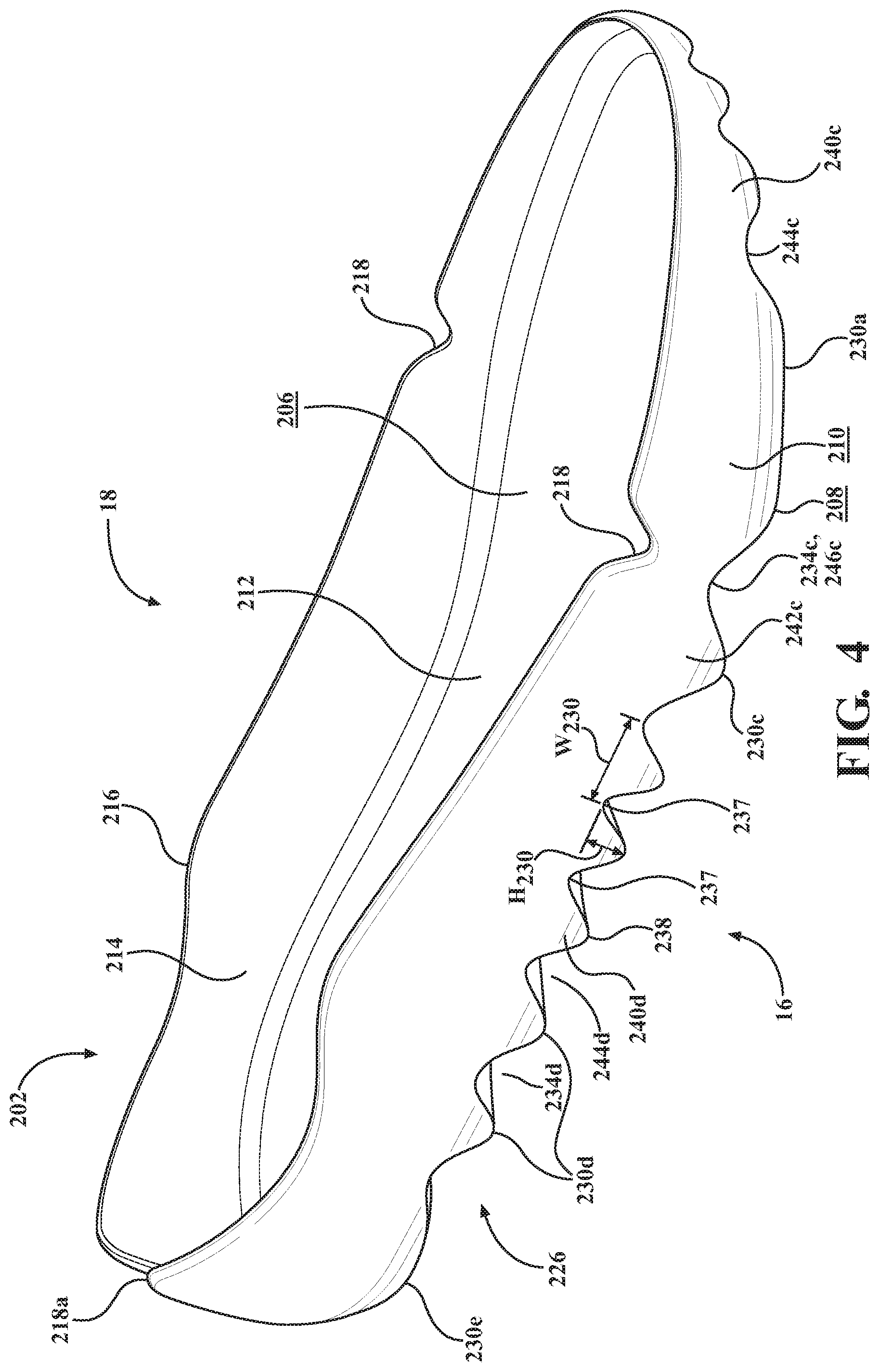
[0094] As shown in FIG. 2, the inner sole element 202 includes a top surface 206 formed on the top of the inner sole element 202, a lower surface 208 formed on an opposite side of the inner sole element 202 from the top surface 206, and a peripheral side surface 210 extending between the top surface 206 and the lower surface 208.
[0095] Referring to FIG. 4, the top surface 206 of the inner sole element 202 may be contoured to define a footbed 212 of the article of footwear 10. Furthermore, the top surface 208 and the peripheral side surface 210 may cooperate to define a sidewall 214 extending away from an outer periphery of the footbed 212 to a distal end 216. The sidewall 214 of the illustrated example extends continuously around the footbed 212. The distal end 216 of the sidewall 214 may include one or more reliefs or notches 218 formed therein, thereby providing sections of the sidewall 214 with a reduced height to improve flexibility of the sole structure 200. In the illustrated example, the inner sole element 202 includes notches 218 formed in the ball region 20.sub.B of the sidewall 214 on the lateral side 16 and the medial side 18, thereby allowing the forefoot region 20 of the sole structure to flex relative to the mid-foot region 22. The sidewall 214 further includes a notch 218a formed in the heel region 24 between the lateral side 16 and the medial side 18 to allow the lateral side 16 of the sole structure 200 to flex independently of the medial side 18 of the sole structure 200 in the heel region 24.
[0096] Referring again to FIG. 2, the outer sole element 204 includes an upper surface 220 formed on the top of the outer sole element 202, a bottom surface 222 formed on an opposite side of the outer sole element 202 from the upper surface 220, and a peripheral side surface 224 extending between the inner surface 220 and the outer surface 222.
[0097] With reference to FIG. 5, the bottom surface 222 of the outer sole element 204 may form a ground-engaging surface of the article of footwear 10. Accordingly, although the bottom surface 222 is illustrated as being substantially smooth, the bottom surface 222 may include a tread profile formed therein. In some examples, an outsole may be attached to the bottom surface 222 to form the ground-engaging surface of the article of footwear.
[0098] As best shown in FIG. 2, when the article of footwear 10 is assembled, the inner sole element 202 is inserted into the interior void 102 so that the lower surface 208 of the inner sole element 202 faces an interior surface of the bottom panel 108 of the sock 106. The outer sole element 204 is positioned on the opposite side of the bottom panel 108 of the sock 106 from the inner sole element 202, so that the upper surface 220 of the outer sole element 204 also faces the bottom panel 108. Accordingly, the bottom panel 108 of the sock 106 will be interposed or sandwiched between the lower surface 208 of the inner sole element 202 and the upper surface 220 of the outer sole element 202. Thus, the lower surface 208 of the inner sole element 202 and the upper surface 220 of the outer sole element 204 may be collectively referred to as the inner surfaces 208, 220 of the sole structure 200, while the top surface 206 of the inner sole element 202 and the bottom surface 222 of the outer sole element 204 may be collectively referred to as the outer surfaces 206, 222 of the sole structure 200.
[0099] With continued reference to FIG. 2, the inner surfaces 208, 220 of the sole elements 202, 204 are configured to interface with each other to form a substantially continuous sole structure 200, wherein the inner surfaces 208, 220 mate with each other when the article of footwear 10 is assembled. As shown, each of the inner surfaces 208, 220 of the sole elements 202, 204 includes a plurality of surface features 226, 228 that are configured to interface or mate with corresponding surface features 226, 228 of the other one of the inner surfaces 208, 220. For example, the surface features 226, 228 may be described as including a plurality of protrusions formed on the inner surface 208 of the inner sole element 202 that are configured to be received in corresponding depressions of the outer sole element 204. Alternatively, the inner sole element 202 may be described as including a plurality of depressions configured to receive corresponding protrusions of the outer sole element 204.
[0100] Generally, a configuration of the surface features 226, 228 is irregular or non-uniform, whereby profiles and arrangements of the surface features 226, 228 vary along the length of the sole structure 200. For example, the surface features 226, 228 may include one or more first surface features 226, 228 having a first size, shape, and/or orientation in a first region 20, 22, 24 of the sole structure 200, and one or more second surface features 226, 228 in a second region 20, 22, 24 of the sole structure 200. Additionally or alternatively, the surface features 226, 228 may vary within any one of the regions 20, 22, 24, from the lateral side 16 to the medial side 18, or a combination thereof.
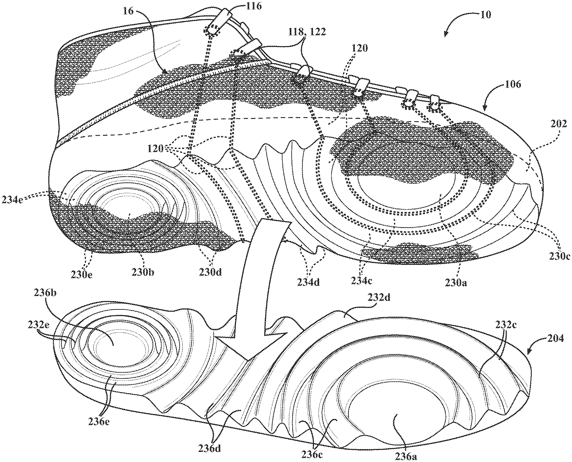
[0101] Referring now to FIG. 6, the surface features 226 of the inner sole element 202 include a first protrusion 230a, a second protrusion 230b, a plurality of third protrusions 230c, a plurality of fourth protrusions 230d, and a plurality of fifth protrusions 230e. Similarly, the outer sole element 204 includes corresponding depressions, including a first depression 236a, a second depression 236b, a plurality of third depressions 236c, a plurality of fourth depressions 236d, and a plurality of fifth depressions 236e, as illustrated in FIG. 7.
[0102] With continued reference to FIG. 6, the first protrusion 230a of the inner sole element 202 is disposed in the forefoot region 20, adjacent to the peripheral side surface 210 on the lateral side 16. As shown, the first protrusion 230a may be continuously formed and entirely disposed inside of the peripheral side surface 210 (i.e., does not intersect the peripheral side surface) of the inner sole element 202. In the illustrated example, the first protrusion 230a is cylindrical in shape and extends to a substantially planer distal end 238a. In other examples, the first protrusion 230a may be polygonal or irregularly shaped. The position of the first protrusion 230a of the inner sole element 202 is configured to correspond to a location of the metatarsophalangeal (MTP) joint on the lateral of the foot. Accordingly, the first protrusion 230a acts as a pad for the MTP joint of the foot during use.
[0103] The second protrusion 230b of the inner sole element 202 is disposed in a central portion of the heel region 24. As shown, the second protrusion 230b is continuously formed and entirely disposed inside of the peripheral side surface 210 (i.e., does not intersect the peripheral side surface) of the inner sole element 202. In the illustrated example, the second protrusion 230b is cylindrical in shape and extends to a substantially planer distal end 238b. In other examples, the second protrusion 230b may be polygonal or irregularly shaped. The position of the second protrusion 230b of the inner sole element 202 is configured to correspond to a location of the calcaneus bone of the foot. Thus, while the first protrusion 230a is offset towards the lateral side 16, the second protrusion 230b is substantially centrally disposed between the lateral side 16 and the medial side 18 of the inner sole element 202, whereby a central axis A.sub.230b of the second protrusion 230b is aligned with the longitudinal axis A.sub.F, as best shown in FIG. 6. Accordingly, the second protrusion 230b acts as a pad for the heel of the foot.
[0104] The plurality of third protrusions 230c includes a plurality of arcuate first ribs 230c that extend around the first protrusion 230a. In the illustrated example, each of the first ribs 230c extends from a first end 240c at the peripheral side surface 210 on the lateral side 16, and around the first protrusion 230a to a second end 242c at the peripheral side surface 210 on the lateral side 16. Accordingly, each of the first ribs 230c extends along a substantially arcuate path. The first end 240c of each first rib 230c is disposed between the first protrusion 230a and the anterior end 12, while the second end 242c is disposed between the first protrusion 230a and the posterior end 14, in the mid-foot region 22.
[0105] With continued reference to FIG. 6, the plurality of fourth protrusions 230d includes a plurality of elongate second ribs 230d that are disposed adjacent to the first ribs 230c and extend continuously from a first end 240d at the peripheral side surface 210 on the lateral side 16 to a second end 242d at the peripheral side surface 210 on the medial side 18. Thus, unlike the first ribs 230c, which are arcuate and extend around the first protrusion 230a from the lateral side 16 and back to the lateral side 16, the second ribs 230d are substantially elongate and extend from the lateral side 16 to the medial side 18. As described below, the second ribs 230d may extend along arcuate paths that are complementary to the paths of adjacent ones of the first ribs 230c, and the third ribs 230e.
[0106] The plurality of fifth protrusions 230e includes a plurality of annular third ribs 230e that extend continuously around the second protrusion 230b. Accordingly, unlike the first ribs 230c and the second ribs 230d, the third ribs 230d do not have ends. Instead, each of the third ribs 230e extends along a continuous circular path having a constant radius measured from a center point of the second protrusion 230b. Thus, the third ribs 230e are concentric with each other and the second protrusion 230b.
[0107] As shown, the second ribs 230d are serially arranged along the mid-foot region 22 between the first ribs 230c and the third ribs 230d. As discussed above, the one or more of the paths along which the second ribs 230d extend may be complementary in shape to the paths of adjacent ones of the first ribs 230c and/or the third ribs 230e. As shown, the second ribs 230d progressively transition from an anterior-facing concave curvature, complementing the arcuate paths of the first ribs 230c, to a posterior-facing concave curvature, complementing the circular paths of the third ribs 230e.
[0108] Each of the ribs 230c-230e may be described as being ridge-shaped, whereby a width W.sub.230 of each rib 230c-230e is measured from a first valley 237c-237e on a first side of the rib 230c-230e to a second valley 237c-237e on an opposite side of the rib 230c-230e, and tapers to a continuous distal end or peak 238c-238e. A height H.sub.230 of each rib 230c-230e is measured from one of the valleys 237 to the peak 238c-238e of the respective rib 230c-230e
[0109] As discussed above, size and spacing of the ribs 230c-230e may be variable, both between of the ribs 230c-230e and along individual ones of the ribs 230c-230e. For example, widths of the first ribs 230c that are adjacent to the first protrusion 230a may be smaller than widths of the first ribs 230c that are spaced apart from the first protrusion 230a. Furthermore, one or more of the first ribs 230c and/or the second ribs 230d may have a greater width at the first end 240c, 240d and/or the second end 242c, 242d than at an intermediate portion. Additionally or alternatively, one or more the ribs 230c-230e may have different cross-sectional shapes. For example, the ribs 230c-230e may have polygonal cross-sections, arcuate cross-sections, or a combination thereof.
[0110] As discussed above, the inner sole element 202 may be described as including a plurality of depressions 234c-234e defined by and disposed between adjacent ones of the protrusions 230a-230c. In the illustrated example, the depressions 234c-234e include a plurality of channels 234c-234e defined by the ribs 230c-230e. Particularly, the inner sole element 202 includes a plurality of first channels 234c defined by the first ribs 230c, which extend from first ends 244c at the peripheral side surface 210 on the lateral side 16 to second ends 246c at the peripheral side surface 210 on the lateral side 16. A plurality of second channels 234c are defined between adjacent ones of the second ribs 230d and each extend from a first end 244d at the peripheral side surface 210 on the lateral side 16 to a second end 246 at the peripheral side surface 210 on the lateral side 16. A plurality of third channels 234c are defined between the third ribs 230e, and each extend along a continuous, circular path in the heel region.
[0111] With reference to FIG. 7, the inner surface 220 of the outer sole element 204 includes a plurality of surface features 228 corresponding to the surface features 226 of the inner sole element 202. For example, the outer sole element 204 includes a plurality of depressions 236a-236e and protrusions 232c-232e configured to mate with the corresponding protrusions 230a-230e and depressions 234c-e of the inner sole element 202. Accordingly, the size, shape, and arrangement of the surface features 228 of the outer sole element 204 will be substantially similar to the size, shape, and arrangement of the corresponding surface features 226, whereby the inner surfaces 208, 220 of the inner sole element 202 and the outer sole element 204 mate with each other. Put another way, when the article of footwear 10 is assembled, peaks 238 of the inner sole element 202 oppose valleys 237 of the outer sole element 204, and vice versa.
[0112] In some examples, materials forming the inner sole element 202 and the outer sole element 204 may be anisotropic, whereby properties of a first portion of the sole structure 200 are different from properties of a second portion of the sole structure 200. In the illustrated example, the material forming the first protrusion 230a may be softer than a material forming the second protrusion 230b.
[0113] As best shown in FIG. 3, when the article of footwear 10 is assembled, the inner sole element 202 is inserted within the interior void 102 of the upper 100 and the bottom panel 108 of the sock 106 conforms to the surface features 226 of the inner sole element 202. Accordingly, the profiles of the protrusions 230a-230e and depressions 234c-234e will be imparted to the bottom panel 108. In some example, the bottom panel 108 may be pre-formed with the profile of the surface features 226, 228.
[0114] As shown, the cables 120 are routed through the sole structure 200 along the valleys 237 of the channels 234c, 234d of the inner sole element 202. Particularly, each of the cables 102 extend from the first end 122 adjacent to the throat opening 112, along the peripheral wall 110 of the sock 106 to the first end 244c, 244d of one of the channels 234c, 234d, through the one of the channels 234c, 234d to the second end 246c, 246c, and back up the peripheral wall 110 to the second end 122 adjacent to the throat opening 112. In the illustrated example, a first pair of the cables 122 are routed through the first channels 234c, whereby the first and second ends 122 of each cable 120 are routed along the lateral side 16 of the upper 100 and are disposed adjacent to the lateral side 16 of the throat opening 120. A second pair of the cables 122 are routed through the second channels 234d, whereby a first end 122 of each cable 120 is routed to the lateral side 16 of the throat opening and a second end 122 of each cable 120 is routed to the medial side 18 of the throat opening 112. Accordingly, the cable ends 122 form a greater number of the apertures 118 on the lateral side 16 of the footwear 10 than on the medial side 18. More particularly, apertures 118 in the forefoot region 20 on the lateral side 16 are formed by the cable ends 122, whereby the cables 120 routed along the lateral side 16 of the upper 100 provide increased responsiveness between the upper 100 and the sole structure 200. The cables 120 may be stitched or knitted or otherwise affixed to or integrated into the peripheral wall 110 of the upper 100.
[0115] With the cables 120 routed through the channels 234c, 234d of the inner sole element 202, the outer sole element 204 can be joined to the inner sole element 202, whereby the bottom panel 108 and the cables 120 will be interposed between the mated surface features 226, 228 of the sole elements 202, 204. Here, the outer sole element 204 may be joined to the inner sole element 202 through the bottom panel 108 using one or more bonding methods, such as adhesive bonding or melding.
[0116] With reference to FIGS. 8-13, an article of footwear 10a constructed according to the principles of the present disclosure is shown. In view of the substantial similarity in structure and function of the components associated with the article of footwear 10 with respect to the article of footwear 10a, like reference numerals are used hereinafter and in the drawings to identify like components while like reference numerals containing letter extensions are used to identify those components that have been modified.
[0117] The article of footwear 10a includes the upper 100 and a sole structure 200a. Referring to FIG. 9, the sole structure 200a of the article of footwear 10a includes the inner sole element 202a and the outer sole element 204a. Generally, the inner sole element 202a and the outer sole element 204a are configured to be disposed on opposite sides of the bottom panel 108 of the sock 106 so that the bottom panel 108 is interposed or sandwiched between the sole elements 202a, 204a.
[0118] As shown in FIG. 9, the inner sole element 202a includes the top surface 206 formed on the top of the inner sole element 202a, a lower surface 208a formed on an opposite side of the inner sole element 202a from the top surface 206, and the peripheral side surface 210 extending between the top surface 206 and the lower surface 208a. The outer sole element 204a includes an upper surface 220a formed on the top of the outer sole element 202a, the bottom surface 222 formed on an opposite side of the outer sole element 202a from the upper surface 220a, and the peripheral side surface 224 extending between the inner surface 220a and the outer surface 222.
[0119] As best shown in FIG. 9, when the article of footwear 10a is assembled, the inner sole element 202a is inserted into the interior void 102 so that the lower surface 208a of the inner sole element 202a faces an interior surface of the bottom panel 108 of the sock 106. The outer sole element 204a is positioned on the opposite side of the bottom panel 108 of the sock 106 from the inner sole element 202a, so that the upper surface 220a of the outer sole element 204a also faces the bottom panel 108. Accordingly, the bottom panel 108 of the sock 106 will be interposed or sandwiched between the lower surface 208a of the inner sole element 202a and the upper surface 220a of the outer sole element 202a. The lower surface 208a of the inner sole element 202a and the upper surface 220a of the outer sole element 204a may be collectively referred to as the inner surfaces 208a, 220a of the sole structure 200a, while the top surface 206 of the inner sole element 202a and the bottom surface 222 of the outer sole element 204a may be collectively referred to as the outer surfaces 206, 222 of the sole structure 200a.
[0120] With continued reference to FIG. 9, the inner surfaces 208a, 220a of the sole elements 202a, 204a are configured to interface with each other to form a substantially continuous sole structure 200a, wherein the inner surfaces 208a, 220a mate with each other when the article of footwear 10a is assembled. As shown, each of the inner surfaces 208a, 220a of the sole elements 202a, 204a includes a plurality of surface features 226, 228 that are configured to interface or mate with corresponding surface features 226, 228 of the other one of the inner surfaces 208a, 220a. For example, the surface features 226, 228 may be described as including a plurality of protrusions formed on the inner surface 208a of the inner sole element 202a that are configured to be received in corresponding depressions of the outer sole element 204a. Alternatively, the inner sole element 202a may be described as including a plurality of depressions configured to receive corresponding protrusions of the outer sole element 204a.
[0121] Generally, a configuration of the surface features 226, 228 is irregular or non-uniform, whereby profiles and arrangements of the surface features 226, 228 vary along the length of the sole structure 200a. For example, the surface features 226, 228 may include one or more first surface features 226, 228 having a first size, shape, and/or orientation in a first region 20, 22, 24 of the sole structure 200a, and one or more second surface features 226, 228 in a second region 20, 22, 24 of the sole structure 200a. Additionally or alternatively, the surface features 226, 228 may vary within any one of the regions 20, 22, 24, from the lateral side 16 to the medial side 18, or a combination thereof.
[0122] Referring now to FIGS. 9 and 12, the surface features 226 of the inner sole element 202a include a first protrusion 230f, a plurality of second protrusions 230g, and a plurality of third protrusions 230h. Similarly, the outer sole element 204a includes corresponding depressions, including a first depression 236f, a plurality of second depressions 236g, and a plurality of third depressions 236h, as illustrated in FIGS. 9 and 13.
[0123] With continued reference to FIG. 12, the first protrusion 230f of the inner sole element 202a is disposed in the forefoot region 20, adjacent to the peripheral side surface 210 on the medial side 18. As shown, the first protrusion 230f may be continuously formed. In the illustrated example, the first protrusion 230f has a frustoconical shape intersecting the peripheral sidewall 210 on the medial side 18, and extends to a substantially planer distal end 238f In other examples, the first protrusion 230f may be polygonal or irregularly shaped. The position of the first protrusion 230f of the inner sole element 202a is configured to correspond to a location of the first metatarsophalangeal (MTP) joint on the medial side 18 of the foot. Accordingly, the first protrusion 230f acts as a pad for the first MTP joint of the foot.
[0124] The plurality of second protrusions 230g includes a plurality of arcuate first ribs 230g that extend around the first protrusion 230f In the illustrated example, each of the first ribs 230g extends from a first end 240g at the peripheral side surface 210 on the medial side 18, and around the first protrusion 230f to a second end 242g at the peripheral side surface 210 on the medial side surface 18. Accordingly, each of the first ribs 230g extends along a substantially arcuate path concentric to a center axis A.sub.230f of the first protrusion 230f The first end 240g of each first rib 230g is disposed between the first protrusion 230f and the anterior end 12, while the second end 242g is disposed between the first protrusion 230f and the posterior end 14, in the mid-foot region 22.
[0125] With continued reference to FIG. 12, the plurality of third protrusions 230h includes a plurality of elongate second ribs 230h that are disposed adjacent to the first ribs 230g and each extend continuously from a first end 240h at the peripheral side surface 210 on the lateral side 16 to a second end 242h at the peripheral side surface 210 on the medial side 18. Thus, unlike the first ribs 230g, which extend from the medial side 18 to the medial side 18, the second ribs 232d are substantially elongate and extend from the lateral side 16 to the medial side 18. However, although the second ribs 230h are substantially elongate, each of the second ribs 230h may extend along an arcuate path from lateral side 16 to the medial side 18. The arcuate paths along which the second ribs 230g extend may be concentric with a center axis A.sub.230f of the first protrusion 230f and/or with the first ribs 230g.
[0126] Each of the ribs 230g, 230h may be described as being ridge-shaped, whereby a width whereby a width W.sub.230 of each rib 230g, 230h is measured from a first valley 237 on a first side of the rib 230g, 230h to a second valley 237 on an opposite side of the rib 230g, 230h, and tapers to a continuous distal end or peak 238.
[0127] As discussed above, size and spacing of the ribs 230g, 230h may be variable, both between the ribs 230g, 230h and along individual ones of the ribs 230g, 230h. As shown, the ribs 230g, 230h are arranged in series from the first protrusion 230f to the posterior end 14, and progressively increase in size along a radial direction away from the first protrusion 230f. For example, heights H.sub.230 and/or widths W.sub.230 of the first ribs 230g that are adjacent to the first protrusion 230f may be smaller than heights H.sub.230 and/or widths W.sub.230 of the first ribs 230g that are farther away from the first protrusion 230f. Likewise, one or more of the first ribs 230g and/or the second ribs 230h may have a greater height or width at the first end 240g, 240h than at the second end 242g, 242h. Additionally or alternatively, one or more the ribs 230g, 230h may have different cross-sectional shapes. For example, the ribs 230g, 230h may have polygonal cross-sections, arcuate cross-sections, or a combination thereof.
[0128] As discussed above, the inner sole element 202a may be described as including a plurality of depressions 234g, 234h defined by and disposed between adjacent ones of the protrusions 230f-230h. In the illustrated example, the depressions 234g, 234h include a plurality of channels 234g, 234h defined by adjacent ones of the ribs 230g, 230h. Particularly, the inner sole element 202a includes a plurality of first channels 234g defined by adjacent ones of the first ribs 230g. The first channels 234g extend from first ends 244g at the peripheral side surface 210 on the medial side 18 to second ends 246g at the peripheral side surface 210 on the medial side 18. A plurality of second channels 234h are defined by adjacent ones of the second ribs 230h, and each extend from a first end 244h at the peripheral side surface 210 on the lateral side 16 to a second end 246h at the peripheral side surface 210 on the medial side 18.
[0129] With reference to FIG. 13, the inner surface 220a of the outer sole element 204a includes a plurality of surface features 228 corresponding to the surface features 226 of the inner sole element 202a. For example, the outer sole element 204a includes a plurality of depressions 236f-236h and protrusions 232g, 232h configured to mate with the corresponding protrusions 230f-230h and depressions 234g, 234h of the inner sole element 202a. Accordingly, the size, shape, and arrangement of the surface features 228 of the outer sole element 204a will be substantially similar to the size, shape, and arrangement of the corresponding surface features 226 of the inner sole element 202a, whereby the inner surfaces 208a, 220a of the inner sole element 202a and the outer sole element 204a mate with each other. Put another way, when the article of footwear 10a is assembled, peaks 238 of the inner sole element 202a oppose valleys 237 of the outer sole element 204a, and vice versa.
[0130] In some examples, materials forming the inner sole element 202a and the outer sole element 204a may be anisotropic, whereby properties of a first portion of the sole structure 200a are different from properties of a second portion of the sole structure 200a. For example, the inner sole element 202a and/or the outer sole element 204a may have a first hardness in a first region 20, 22, 24 of the sole structure 200a and a second hardness in a second region 20, 22, 24 of the sole structure 200a.
[0131] As best shown in FIG. 8, when the article of footwear 10a is assembled, the inner sole element 202a is inserted within the interior void 102 of the upper 100 and the bottom panel 108 of the sock 106 conforms to the surface features 226 of the inner sole element 202a. Accordingly, the profiles of the protrusions 230f-230h and depressions 234g, 234h will be imparted to the bottom panel 108. The outer sole element 204a is then attached to the opposite side of the bottom panel 108 on the exterior of the upper 100, whereby the bottom panel 108 will be interposed between the mated surface features 226, 228 of the sole elements 202a, 204a. Here, the outer sole element 204a may be joined to the inner sole element 202a through the bottom panel 108 using one or more bonding methods, such as adhesive bonding or melding.
[0132] Although not shown in the illustrated example, the article of footwear 10a may include one or more of the cables 120 extending from a first end 122 adjacent to the throat opening 112, through one or more of the channels 234g, 230h of the inner sole element 202a, and back to a second end 122 adjacent to the throat opening 112.
[0133] With reference to FIGS. 14-19, an article of footwear 10b constructed according to the principles of the present disclosure is shown. In view of the substantial similarity in structure and function of the components associated with the article of footwear 10 with respect to the article of footwear 10b, like reference numerals are used hereinafter and in the drawings to identify like components while like reference numerals containing letter extensions are used to identify those components that have been modified.
[0134] The article of footwear 10b includes the upper 100 and a sole structure 200b. The sole structure 200b of the article of footwear 10b includes the inner sole element 202b and the outer sole element 204b. Generally, the inner sole element 202b and the outer sole element 204b are configured to be disposed on opposite sides of the bottom panel 108 of the sock 106 so that the bottom panel 108 is interposed or sandwiched between the sole elements 202b, 204b.
[0135] As shown in FIG. 14, the inner sole element 202b includes the top surface 206 formed on the top of the inner sole element 202b, a lower surface 208b formed on an opposite side of the inner sole element 202b from the top surface 206, and the peripheral side surface 210 extending between the top surface 206 and the lower surface 208b. The outer sole element 204b includes an upper surface 220b formed on the top of the outer sole element 202b, the bottom surface 222 formed on an opposite side of the outer sole element 202b from the upper surface 220b, and the peripheral side surface 224 extending between the inner surface 220b and the outer surface 222.
[0136] As best shown in FIG. 14, when the article of footwear 10b is assembled, the inner sole element 202b is inserted into the interior void 102 so that the lower surface 208b of the inner sole element 202b faces an interior surface of the bottom panel 108 of the sock 106. The outer sole element 204b is positioned on the opposite side of the bottom panel 108 of the sock 106 from the inner sole element 202b, so that the upper surface 220b of the outer sole element 204b faces an exterior surface of the bottom panel 108. Accordingly, the bottom panel 108 of the sock 106 will be interposed or sandwiched between the lower surface 208b of the inner sole element 202b and the upper surface 220b of the outer sole element 202b. The lower surface 208b of the inner sole element 202b and the upper surface 220b of the outer sole element 204b may be collectively referred to as the inner surfaces 208b, 220b of the sole structure 200b, while the top surface 206 of the inner sole element 202b and the bottom surface 222 of the outer sole element 204b may be collectively referred to as the outer surfaces 206, 222 of the sole structure 200b.
[0137] With continued reference to FIG. 14, the inner surfaces 208b, 220b of the sole elements 202b, 204b are configured to interface with each other to form a substantially continuous sole structure 200b, wherein the inner surfaces 208b, 220b mate with each other when the article of footwear 10b is assembled. As shown, each of the inner surfaces 208b, 220b of the sole elements 202b, 204b includes a plurality of surface features 226, 228 that are configured to interface or mate with corresponding surface features 226, 228 of the other one of the inner surfaces 208b, 220b. For example, the surface features 226, 228 may be described as including a plurality of protrusions formed on the inner surface 208b of the inner sole element 202b that are configured to be received in corresponding depressions of the outer sole element 204b. Alternatively, the inner sole element 202b may be described as including a plurality of depressions configured to receive corresponding protrusions of the outer sole element 204b.
[0138] Generally, a configuration of the surface features 226, 228 is irregular or non-uniform, whereby profiles and arrangements of the surface features 226, 228 vary along the sole structure 200b. For example, the surface features 226, 228 may include one or more first surface features 226, 228 having a first size, shape, and/or orientation in a first region 20, 22, 24 of the sole structure 200b, and one or more second surface features 226, 228 in a second region 20, 22, 24 of the sole structure 200b. Additionally or alternatively, the surface features 226, 228 may vary within any one of the regions 20, 22, 24, from the lateral side 16 to the medial side 18, or a combination thereof.
[0139] Referring now to FIG. 15, the surface features 226 of the inner sole element 202b include a plurality of first protrusions 230i in the heel region 24 and a plurality of second protrusions 230j serially arranged between the heel region 24 and the anterior end 12. Similarly, the outer sole element 204b includes corresponding depressions, including a plurality of first depressions 236i and a plurality of second depressions 236j, as illustrated in FIG. 15.
[0140] With reference to FIGS. 15 and 18, the first protrusions 230i of the inner sole element 202b are disposed in the heel region 24, adjacent to the peripheral side surface 210 on the medial side 18. The plurality of first protrusions 230i includes a plurality of annular first ribs 230i disposed in the heel region 24. As shown, the first ribs 230i are concentrically arranged about an axis A.sub.230i in a central portion of the heel region 24.
[0141] The plurality of second protrusions 230j includes a plurality of arcuate, elongate second ribs 230j that are disposed adjacent and concentric to the first ribs 230i. Each of the second ribs 230j extends continuously from a first end 240j at the peripheral side surface 210 on the lateral side 16 to a second end 242j at the peripheral side surface 210 on the medial side 18. Thus, unlike the first ribs 230i, which are annular and continuous, the second ribs 232d are substantially elongate and extend from the lateral side 16 to the medial side 18. Although, the second ribs 230j are substantially elongate, each of the second ribs 230j may extend along an arcuate path from the lateral side 16 to the medial side 18. In the illustrated example, the second ribs 230j are concentric with each other and the first ribs 230i about the axis A.sub.230i.
[0142] Each of the ribs 230i, 230j may be described as being ridge-shaped, whereby a width W.sub.230 of each rib 230i, 230j is measured from a first valley 237 on a first side of the rib 230g, 230h to a second valley 237 on an opposite side of the rib 230i, 230j, and tapers to a continuous distal end or peak 238. Additionally or alternatively, one or more the ribs 230i, 230j may have different cross-sectional shapes. For example, the ribs 230i, 230j may have polygonal cross-sections, arcuate cross-sections, or a combination thereof.
[0143] As discussed above, size, shape, and/or orientation of the ribs 230i, 230j may be variable between the ribs 230i, 230j. As shown, the second ribs 230j are arranged in series from the first ribs 230i to the anterior end 12, and progressively change in size along a radial direction from the first ribs 230i to the anterior end. For example, widths W.sub.230 of the second ribs 230j that are adjacent to the first ribs 230i may be smaller than widths W.sub.230 of the second ribs 230j that are farther away from the first ribs 230i, while heights H.sub.230 of the second ribs 230j that are adjacent to the first ribs 230i may be greater than heights H.sub.230 of the second ribs 230j that are farther away from the first ribs 230i. In this example, the height H.sub.230 and width W.sub.230 of each of the ribs 230i, 230j are substantially constant along the entire length of each rib 230i, 230j.
[0144] As discussed previously, the inner sole element 202b may be described as including a plurality of depressions 234i, 234j defined by and disposed between adjacent ones of the protrusions 230i, 230j. In the illustrated example, the depressions 234i, 234j include a plurality of channels 234i, 234j defined by adjacent ones of the protrusions 230i, 230j. Particularly, the inner sole element 202b includes a plurality of annular first channels 234i defined by the first ribs 230i. A plurality of second channels 234j are defined by the second ribs 230j, and each extend from a first end 244j at the peripheral side surface 210 on the lateral side 16 to a second end 246j at the peripheral side surface 210 on the medial side 18.
[0145] With reference to FIG. 19, the inner surface 220b of the outer sole element 204b includes a plurality of surface features 228 corresponding to the surface features 226 of the inner sole element 202b. For example, the outer sole element 204b includes a plurality of depressions 236i, 236j and protrusions 232i, 232j configured to mate with the corresponding protrusions 230i, 230j and depressions 234i, 234j of the inner sole element 202b. Accordingly, the size, shape, and arrangement of the surface features 228 of the outer sole element 204b will be substantially similar to the size, shape, and arrangement of the cooperating surface features 226 of the inner sole element 202b, whereby the inner surfaces 208b, 220b of the inner sole element 202b and the outer sole element 204b are configured to mate with each other. Put another way, when the article of footwear 10b is assembled, peaks 238 of the inner sole element 202b oppose valleys 237 of the outer sole element 204b, and vice versa.
[0146] In some examples, materials forming the inner sole element 202b and the outer sole element 204b may be anisotropic, whereby properties of a first portion of the sole structure 200b are different from properties of a second portion of the sole structure 200b. For example, the inner sole element 202b and/or the outer sole element 204b may have a first hardness in a first region 20, 22, 24 of the sole structure 200b and a second hardness in a second region 20, 22, 24 of the sole structure 200b.
[0147] As best shown in FIG. 14, when the article of footwear 10b is assembled, the inner sole element 202b is inserted within the interior void 102 of the upper 100 and the bottom panel 108 of the sock 106 conforms to the surface features 226 of the inner sole element 202b. Accordingly, the profiles of the protrusions 230i, 230j and depressions 234i, 234j will be imparted to the bottom panel 108. The outer sole element 204b is then attached to the opposite side of the bottom panel 108 on the exterior of the upper 100, whereby the bottom panel 108 will be interposed between the mated surface features 226, 228 of the sole elements 202b, 204b. Here, the outer sole element 204 may be joined to the inner sole element 202 through the bottom panel 108 using one or more bonding methods, such as adhesive bonding or melding. Although not shown in the illustrated example, the article of footwear 10b may include one or more of the cables 120 extending from a first end 122 adjacent to the throat opening 112, through one or more of the channels 234i, 230j of the inner sole element 202a, and back to a second end 122 adjacent to the throat opening 112.
[0148] With reference to FIGS. 20-25, an article of footwear 10c constructed according to the principles of the present disclosure is shown. In view of the substantial similarity in structure and function of the components associated with the article of footwear 10 with respect to the article of footwear 10c, like reference numerals are used hereinafter and in the drawings to identify like components while like reference numerals containing letter extensions are used to identify those components that have been modified.
[0149] The article of footwear 10c includes the upper 100 and a sole structure 200c. Referring to FIG. 20, the sole structure 200c of the article of footwear 10c includes the inner sole element 202c and an outer sole element 204c. Generally, the inner sole element 202c and the outer sole element 204c are configured to be disposed on opposite sides of the bottom panel 108 of the sock 106 so that the bottom panel 108 is interposed or sandwiched between the sole elements 202c, 204c.
[0150] As shown in FIG. 22, the inner sole element 202c includes the top surface 206 formed on the top of the inner sole element 202c, a lower surface 208c formed on an opposite side of the inner sole element 202c from the top surface 206, and the peripheral side surface 210 extending between the top surface 206 and the lower surface 208c. With reference to FIG. 23, the outer sole element 204c includes an upper surface 220c formed on the top of the outer sole element 202c, the bottom surface 222 formed on an opposite side of the outer sole element 202c from the upper surface 220c, and the peripheral side surface 224 extending between the inner surface 220c and the outer surface 222.
[0151] Referring to FIGS. 20 and 21, when the article of footwear 10c is assembled, the inner sole element 202c is inserted into the interior void 102 so that the lower surface 208c of the inner sole element 202c faces an interior surface of the bottom panel 108 of the sock 106. The outer sole element 204c is positioned on the opposite side of the bottom panel 108 of the sock 106 from the inner sole element 202c, so that the upper surface 220c of the outer sole element 204c faces an exterior surface of the bottom panel 108. Accordingly, the bottom panel 108 of the sock 106 will be interposed or sandwiched between the lower surface 208c of the inner sole element 202c and the upper surface 220c of the outer sole element 202c. The lower surface 208c of the inner sole element 202c and the upper surface 220c of the outer sole element 204c may be collectively referred to as the inner surfaces 208c, 220c of the sole structure 200c, while the top surface 206 of the inner sole element 202c and the bottom surface 222 of the outer sole element 204c may be collectively referred to as the outer surfaces 206, 222 of the sole structure 200c.
[0152] With continued reference to FIG. 20, the inner surfaces 208c, 220c of the sole elements 202c, 204c are configured to interface with each other to form a substantially continuous sole structure 200c, wherein the inner surfaces 208c, 220c mate with each other when the article of footwear 10c is assembled. The lower, inner surface 208c of the inner sole element 202c includes a plurality of surface features 226 that are configured to interface or mate with corresponding surface features 228 of the upper, inner surface 220c of the outer sole element 204c. For example, the surface features 226 of the inner sole element 202c may be described as including a plurality of protrusions formed on the inner surface 208c of the inner sole element 202c, while the surface features 228 of the outer sole element 204c includes a plurality of depressions corresponding to the protrusions of the inner sole element 202c. Additionally or alternatively, the inner sole element 202c may be described as including a plurality of depressions configured to receive corresponding protrusions of the outer sole element 204c.
[0153] Generally, a configuration of the surface features 226, 228 is irregular or non-uniform, whereby profiles and arrangements of the surface features 226, 228 vary along the sole structure 200c. For example, the surface features 226, 228 may include one or more first surface features 226, 228 having a first size, shape, and/or orientation in a first region 20, 22, 24 of the sole structure 200c, and one or more second surface features 226, 228 in a second region 20, 22, 24 of the sole structure 200c. Additionally or alternatively, the surface features 226, 228 may vary within any one of the regions 20, 22, 24, from the lateral side 16 to the medial side 18, or a combination thereof.
[0154] Referring now to FIG. 21, the surface features 226 of the inner sole element 202c include a plurality of first protrusions 230k in the heel region 24 and a plurality of second protrusions 230m serially arranged between the first protrusion 230k and the anterior end 12. Generally, the first protrusions 230k and the second protrusions 230m may be described as being arranged in a nautilus pattern, whereby the first protrusions 230k are radially arranged about an axis A.sub.230K in the heel region 24 and the second protrusions 230m are serially spaced along the mid-foot region 22 and the forefoot region 20. The outer sole element 204c includes corresponding depressions, including a plurality of first depressions 236k and a plurality of second depressions 236m, which are respectively configured to receive corresponding ones of the protrusions 230k, 230m.
[0155] With continued reference to FIG. 21, the plurality of first protrusions 230k includes a plurality of tapered, elongate first ribs 230k disposed in the heel region 24, while the plurality of second protrusions 230m includes a plurality of tapered, elongate second ribs 230m disposed in the mid-foot region 22 and the forefoot region 20. Each of the ribs 230k, 230m may be described as being ridge-shaped, whereby the width W.sub.230 of each rib 230k, 230m is measured from a first valley 237 on a first side of the rib 230k, 230m to a second valley 237 on an opposite side of the rib 230k, 230m, and tapers to a continuous distal end or peak 238.
[0156] As shown, the first ribs 230k are radially arranged about an axis A.sub.230k of a central portion 229 of the heel region 24. The region of the inner surface 208c formed by the central portion 229 is substantially planar, and free of the surface features 226. In some examples, the peaks 238 of the first ribs 230k are substantially coplanar with the central portion 229, while a depth D.sub.234 of the first depressions 234k defined by the first ribs 230k increases along a radial direction away from the central portion 229. Accordingly, an effective height H.sub.230 of the first ribs 230 also increases progressively or continuously along the radial direction away from the central portion 229.
[0157] In the illustrated example, a periphery of the central portion 229 is teardrop-shaped--tapering in a direction form the posterior end 14 to the anterior end 12--and the first protrusions 230k project radially outwardly therefrom. Particularly, a first one of the first ribs 230k extends from a first end 240k on a medial side 18 of the central portion 229 to a second end 242k at the peripheral sidewall 210 on the medial side 18 of the inner sole element 202c, while a last one of the first ribs 230k extends from a first end 240k on a lateral side 16 of the central portion 229 to a second end 242k at the peripheral sidewall 210 on the lateral side 16 of the inner sole element 202c. A series of intermediate ones of the first ribs 230k are spaced between the first and last ones of the first ribs 230k, whereby the central portion 229 is completely surrounded by the first ribs 230k. As discussed above, the height H.sub.230 of each of the first ribs 230k (i.e. a depth D.sub.234 of the channel 234k) increases continuously in a direction from the first end 240k to the second end 242k.
[0158] With continued reference to FIG. 21, the second ribs 230m are serially spaced along the mid-foot region 22 and the forefoot region 20. Each of the second ribs 230m extends continuously from a terminal first end 240m on the medial side 18 of the inner sole element 202c to a second end 242m at the peripheral side surface 210 on the lateral side 16. As shown, the first end 240m is spaced inwardly from the peripheral side surface 210 on the medial side 18. As with the first ribs 230k, a height H.sub.230 of each of the second ribs 230m (i.e. a depth D.sub.234 of the channel 234m) increases from the first end 240m to the second end 242m.
[0159] As indicated in FIG. 24, a first one of second ribs 230m is disposed adjacent to the last one of the first ribs 230k on the lateral side 16 in the heel region 24, while a last one of the second ribs 230m is disposed in the toe portion 20.sub.T of the forefoot region 20. A series of intermediate ones of the second ribs 230m are spaced between the first and the last ones of the second ribs 230m. In the illustrated example, the second ribs 230m each extend along a lateral direction of the article of footwear (i.e., from the lateral side to the medial side, transverse to the longitudinal axis A.sub.F). Two or more of the second ribs 230m may be parallel to each other.
[0160] As discussed above, the inner sole element 202c may be described as including a plurality of depressions 234k, 234m defined by and disposed between adjacent ones of the ribs 230k, 230m. In the illustrated example, the depressions 234k, 234m include a plurality of channels 234k, 234m defined by adjacent ones of the ribs 230k, 230m. Particularly, the inner sole element 202c includes a plurality of elongate first channels 234k defined by the first ribs 230k extending radially outwardly from a first end 244k at the central portion 229 to a second end 246k at the peripheral sidewall 210. A plurality of second channels 234m are defined by the second ribs 230m, and each extend from a first end 244m adjacent to the medial side 18 of the inner surface 208m to a second end 246m at the peripheral side surface 210 on the lateral side 16.
[0161] With reference to FIG. 25, the inner surface 220c of the outer sole element 204c includes a plurality of surface features 228 corresponding to the surface features 226 of the inner sole element 202c. For example, the outer sole element 204c includes a plurality of depressions 236k, 236m and protrusions 232k, 232m configured to mate with the corresponding protrusions 230k, 230m and depressions 234k, 234m of the inner sole element 202c. Accordingly, the size, shape, and arrangement of the surface features 228 of the outer sole element 204c will be substantially similar to the size, shape, and arrangement of the cooperating surface features 226 of the inner sole element 202c, whereby the inner surfaces 208c, 220c of the inner sole element 202c and the outer sole element 204c are configured to mate with each other. Put another way, when the article of footwear 10c is assembled, peaks 238 of the inner sole element 202c oppose valleys 237 of the outer sole element 204c, and vice versa.
[0162] In some examples, materials forming the inner sole element 202c and the outer sole element 204c may be anisotropic, whereby properties of a first portion of the sole structure 200c are different from properties of a second portion of the sole structure 200c. For example, the inner sole element 202c and/or the outer sole element 204c may have a first hardness in a first region 20, 22, 24 of the sole structure 200c and a second hardness in a second region 20, 22, 24 of the sole structure 200c.
[0163] As best shown in FIG. 20, when the article of footwear 10c is assembled, the inner sole element 202c is inserted within the interior void 102 of the upper 100 and the bottom panel 108 of the sock 106 conforms to the surface features 226 of the inner sole element 202c. Accordingly, the profiles of the protrusions 230k, 230m and depressions 234k, 234m will be imparted to the bottom panel 108. The outer sole element 204c is then attached to the opposite side of the bottom panel 108 on the exterior of the upper 100, whereby the bottom panel 108 will be interposed between the mated surface features 226, 228 of the sole elements 202c, 204c. Here, the outer sole element 204c may be joined to the inner sole element 202c through the bottom panel 108 using one or more bonding methods, such as adhesive bonding or melding. Although not shown in the illustrated example, the article of footwear 10c may include one or more of the cables 120 extending from a first end 122 adjacent to the throat opening 112, through one or more of the channels 234k, 230m of the inner sole element 202a, and back to a second end 122 adjacent to the throat opening 112.
[0164] With reference to FIGS. 26-31, an article of footwear 10d constructed according to the principles of the present disclosure is shown. In view of the substantial similarity in structure and function of the components associated with the article of footwear 10 with respect to the article of footwear 10d, like reference numerals are used hereinafter and in the drawings to identify like components while like reference numerals containing letter extensions are used to identify those components that have been modified.
[0165] The article of footwear 10d includes the upper 100 and a sole structure 200d. Referring to FIG. 27, the sole structure 200d of the article of footwear 10d includes the inner sole element 202d and an outer sole element 204d. Generally, the inner sole element 202d and the outer sole element 204d are configured to be disposed on opposite sides of the bottom panel 108 of the sock 106 so that the bottom panel 108 is interposed or sandwiched between the sole elements 202d, 204d.
[0166] As shown in FIG. 28, the inner sole element 202d includes the top surface 206 formed on the top of the inner sole element 202d, a lower surface 208d formed on an opposite side of the inner sole element 202d from the top surface 206, and the peripheral side surface 210 extending between the top surface 206 and the lower surface 208d. With reference to FIG. 29, the outer sole element 204d includes an upper surface 220d formed on the top of the outer sole element 202d, the bottom surface 222 formed on an opposite side of the outer sole element 202d from the upper surface 220d, and the peripheral side surface 224 extending between the inner surface 220d and the outer surface 222.
[0167] Referring to FIGS. 26 and 27, when the article of footwear 10d is assembled, the inner sole element 202d is inserted into the interior void 102 so that the lower surface 208d of the inner sole element 202d faces an interior surface of the bottom panel 108 of the sock 106. The outer sole element 204d is positioned on the opposite side of the bottom panel 108 of the sock 106 from the inner sole element 202d, so that the upper surface 220d of the outer sole element 204d faces an exterior surface of the bottom panel 108. Accordingly, the bottom panel 108 of the sock 106 will be interposed or sandwiched between the lower surface 208d of the inner sole element 202d and the upper surface 220d of the outer sole element 202d. The lower surface 208d of the inner sole element 202d and the upper surface 220d of the outer sole element 204d may be collectively referred to as the inner surfaces 208d, 220d of the sole structure 200d, while the top surface 206 of the inner sole element 202d and the bottom surface 222 of the outer sole element 204d may be collectively referred to as the outer surfaces 206, 222 of the sole structure 200d.
[0168] With continued reference to FIG. 26, the inner surfaces 208d, 220d of the sole elements 202d, 204d are configured to interface with each other to form a substantially continuous sole structure 200d, wherein the inner surfaces 208d, 220d mate with each other when the article of footwear 10d is assembled. The lower, inner surface 208d of the inner sole element 202d includes a plurality of surface features 226 that are configured to interface or mate with corresponding surface features 228 of the upper, inner surface 220d of the outer sole element 204d. For example, the surface features 226 of the inner sole element 202d may be described as including a plurality of protrusions 230n, 230p and depressions 234p, 234n formed on the inner surface 208d of the inner sole element 202d, while the surface features 228 of the outer sole element 204d includes a plurality of depressions 236p, 236n and protrusions 232p, 232n respectively configured to interface with the protrusions 230n, 230p and depressions 234p, 234n of the inner sole element 202d.
[0169] Generally, a configuration of the surface features 226, 228 is irregular or non-uniform, whereby profiles and arrangements of the surface features 226, 228 vary along the sole structure 200d. For example, the surface features 226, 228 may include one or more first surface features 226, 228 having a first size, shape, and/or orientation in a first region 20, 22, 24 of the sole structure 200d, and one or more second surface features 226, 228 in a second region 20, 22, 24 of the sole structure 200d. Additionally or alternatively, the surface features 226, 228 may vary within any one of the regions 20, 22, 24, from the lateral side 16 to the medial side 18, or a combination thereof.
[0170] Referring now to FIG. 27, the surface features 226 of the inner sole element 202d include a plurality of first protrusions 230n and a plurality of second protrusions 230p. The outer sole element 204d includes corresponding depressions 236n, 236p, including a plurality of first depressions 236n and a plurality of second depressions 236p, which are configured to receive the protrusions 230n, 230p when the inner sole element 202c and the outer sole element 204c are assembled.
[0171] Generally, the first protrusions 230n include a plurality of first tapered ribs 230n and the second protrusions 230p include a plurality of second tapered ribs 230p. Each of the ribs 230n, 230p may be described as being ridge-shaped, whereby the width W.sub.230 of each rib 230n, 230p is measured from a first valley 237 on a first side of the rib 230n, 230p to a second valley 237 on an opposite side of the rib 230n, 230p, and tapers to a continuous distal end or peak 238. The ribs 230n, 230p may be described as being arranged in a compound starburst pattern, whereby the first ribs 230n are arranged as a first radial array in the forefoot region 20 and converge with each other in a direction from the lateral side 16 to the medial side 18, and the second ribs 230p are arranged as a second radial array in the heel region 24 and converge with each other in a direction from the medial side 18 to the lateral side 16, as best shown in FIG. 30.
[0172] As shown, the first ribs 230n are arranged in a first starburst pattern in the forefoot region 20. Each of the first ribs 230n extends continuously across the inner surface 208c, from a first end 240n at the peripheral sidewall 210 on the lateral side 16 to a second end 242n at the peripheral sidewall 210 on the medial side 18. As discussed above, the first ribs 230n converge with each other along the direction from the lateral side 16 to the medial side 18. As shown in FIG. 30, a first one of the first ribs 230n is disposed at the anterior end 12 inner sole element 202d and a last one of the first ribs 230n is disposed in the mid-foot region 22 of the inner sole element 202d, while intermediate ones of the first ribs 230n are serially spaced between the first and last ribs 230n. The first ribs 230n may be arranged in a radial array about a first axis A.sub.230n on the medial side 18 of the inner sole element 202c.
[0173] As shown, the second ribs 230p are arranged in a second starburst pattern in the heel region 24, whereby the second ribs 230p extend continuously across the inner surface 208c, from a first end 240p at the peripheral sidewall 210 on the lateral side 16 to a second end 242p at the peripheral sidewall 210 on the medial side 18. In contrast to the first ribs 230n, the second ribs 230p converge with each other along the direction from the medial side 18 to the lateral side 16. As shown in FIG. 30, a first one of the second ribs 230p is disposed in the mid-foot region 22 adjacent to the last one of the first ribs 230n and a last one of the second ribs 230p is disposed at the anterior end 14, while intermediate ones of the second ribs 230p are serially spaced between the first and last ribs 230p. Two or more of the second ribs 230p may extend radially from a second axis A.sub.230p on the lateral side 16 of the inner sole element 202c.
[0174] As shown in FIG. 30, the inner sole element 202d may include a plurality of ribs 230n-p in the mid-foot region 22 that converge with the first ribs 230n or the second ribs 230p, but are not arranged about either of the axes A.sub.230n, A.sub.230p. These ribs 230n-p may be referred to as transitional ribs 230n-p that progressively transition from the lateral-to-medial convergence of first ribs 230n to the medial-to-lateral convergence of the second ribs 230p. Accordingly, the ribs 230n, 230p, 230n-p cooperate to define a compound radial array having a first portion and a reversed second portion.
[0175] As discussed above, the inner sole element 202d may be described as including a plurality of depressions 234n, 234p defined by and disposed between adjacent ones of the ribs 230n, 230p. In the illustrated example, the depressions 234n, 234p include a plurality of channels 234n, 234p defined by adjacent ones of the ribs 230n, 230p. Particularly, the inner sole element 202d includes a plurality of elongate first channels 234n defined by the first ribs 230n extending from a first end 244m at the peripheral sidewall 210 on the lateral side 16 to a second end 246m at the peripheral sidewall 210 on the medial side 18. A plurality of second channels 234p are defined by the second ribs 230p, and each extend from a first end 244m on the lateral side 16 of the inner surface 208m to a second end 246m at the peripheral side surface 210 on the medial side 18.
[0176] With reference to FIG. 31, the inner surface 220d of the outer sole element 204d includes a plurality of surface features 228 corresponding to the surface features 226 of the inner sole element 202d. For example, the outer sole element 204d includes a plurality of depressions 236n, 236p and protrusions 232n, 232p configured to mate with the corresponding protrusions 230n, 230p and depressions 234n, 234p of the inner sole element 202d. Accordingly, the size, shape, and arrangement of the surface features 228 of the outer sole element 204d will be substantially similar to the size, shape, and arrangement of the cooperating surface features 226 of the inner sole element 202d, whereby the inner surfaces 208d, 220d of the inner sole element 202d and the outer sole element 204d are configured to mate with each other. Put another way, when the article of footwear 10d is assembled, peaks 238 of the inner sole element 202d oppose valleys 237 of the outer sole element 204d, and vice versa.
[0177] In some examples, materials forming the inner sole element 202d and the outer sole element 204d may be anisotropic, whereby properties of a first portion of the sole structure 200d are different from properties of a second portion of the sole structure 200d. For example, the inner sole element 202d and/or the outer sole element 204d may have a first hardness in a first region 20, 22, 24 of the sole structure 200d and a second hardness in a second region 20, 22, 24 of the sole structure 200d.
[0178] As best shown in FIG. 26, when the article of footwear 10d is assembled, the inner sole element 202d is inserted within the interior void 102 of the upper 100 and the bottom panel 108 of the sock 106 conforms to the surface features 226 of the inner sole element 202d. Accordingly, the profiles of the protrusions 230n, 230p and depressions 234n, 234p will be imparted to the bottom panel 108. The outer sole element 204d is then attached to the opposite side of the bottom panel 108 on the exterior of the upper 100, whereby the bottom panel 108 will be interposed between the mated surface features 226, 228 of the sole elements 202d, 204d. Although not shown, the article of footwear 10d may incorporate one or more of the cables 120, whereby each cable 120 extends from lateral side 16 of the throat opening 112, along the peripheral wall 110 of the sock 106, through the sole structure 200d along one of the channels 234n, 234p, and back up the peripheral wall 110 to the lateral side 18 of the throat opening 112.
[0179] As described above, the sole elements 202-202d, 204-204d are formed of a resilient polymeric material, such as foam or rubber, to impart properties of cushioning, responsiveness, and energy distribution to the foot of the wearer. As discussed, the sole elements 202-202d, 204-204d may be anisotropic, whereby a first portion of the respective sole element 202-202d, 204-204d has different properties than a second portion of the sole element 202-202d, 204-204d. For example, one or more of the surface features 226, 228 may have a first hardness while a second one of the surface features 226, 228 has a second hardness.
[0180] Example resilient polymeric materials for sole elements 202-202d, 204-204d may include those based on foaming or molding one or more polymers, such as one or more elastomers (e.g., thermoplastic elastomers (TPE)). The one or more polymers may include aliphatic polymers, aromatic polymers, or mixtures of both; and may include homopolymers, copolymers (including terpolymers), or mixtures of both.
[0181] In some aspects, the one or more polymers may include olefinic homopolymers, olefinic copolymers, or blends thereof. Examples of olefinic polymers include polyethylene, polypropylene, and combinations thereof In other aspects, the one or more polymers may include one or more ethylene copolymers, such as, ethylene-vinyl acetate (EVA) copolymers, EVOH copolymers, ethylene-ethyl acrylate copolymers, ethylene-unsaturated mono-fatty acid copolymers, and combinations thereof.
[0182] In further aspects, the one or more polymers may include one or more polyacrylates, such as polyacrylic acid, esters of polyacrylic acid, polyacrylonitrile, polyacrylic acetate, polymethyl acrylate, polyethyl acrylate, polybutyl acrylate, polymethyl methacrylate, and polyvinyl acetate; including derivatives thereof, copolymers thereof, and any combinations thereof.
[0183] In yet further aspects, the one or more polymers may include one or more ionomeric polymers. In these aspects, the ionomeric polymers may include polymers with carboxylic acid functional groups, sulfonic acid functional groups, salts thereof (e.g., sodium, magnesium, potassium, etc.), and/or anhydrides thereof. For instance, the ionomeric polymer(s) may include one or more fatty acid-modified ionomeric polymers, polystyrene sulfonate, ethylene-methacrylic acid copolymers, and combinations thereof.
[0184] In further aspects, the one or more polymers may include one or more styrenic block copolymers, such as acrylonitrile butadiene styrene block copolymers, styrene acrylonitrile block copolymers, styrene ethylene butylene styrene block copolymers, styrene ethylene butadiene styrene block copolymers, styrene ethylene propylene styrene block copolymers, styrene butadiene styrene block copolymers, and combinations thereof.
[0185] In further aspects, the one or more polymers may include one or more polyamide copolymers (e.g., polyamide-polyether copolymers) and/or one or more polyurethanes (e.g., cross-linked polyurethanes and/or thermoplastic polyurethanes). Alternatively, the one or more polymers may include one or more natural and/or synthetic rubbers, such as butadiene and isoprene.
[0186] When the resilient polymeric material is a foamed polymeric material, the foamed material may be foamed using a physical blowing agent which phase transitions to a gas based on a change in temperature and/or pressure, or a chemical blowing agent which forms a gas when heated above its activation temperature. For example, the chemical blowing agent may be an azo compound such as adodicarbonamide, sodium bicarbonate, and/or an isocyanate.
[0187] In some embodiments, the foamed polymeric material may be a crosslinked foamed material. In these embodiments, a peroxide-based crosslinking agent such as dicumyl peroxide may be used. Furthermore, the foamed polymeric material may include one or more fillers such as pigments, modified or natural clays, modified or unmodified synthetic clays, talc glass fiber, powdered glass, modified or natural silica, calcium carbonate, mica, paper, wood chips, and the like.
[0188] The resilient polymeric material may be formed using a molding process. In one example, when the resilient polymeric material is a molded elastomer, the uncured elastomer (e.g., rubber) may be mixed in a Banbury mixer with an optional filler and a curing package such as a sulfur-based or peroxide-based curing package, calendared, formed into shape, placed in a mold, and vulcanized.
[0189] In another example, when the resilient polymeric material is a foamed material, the material may be foamed during a molding process, such as an injection molding process. A thermoplastic polymeric material may be melted in the barrel of an injection molding system and combined with a physical or chemical blowing agent and optionally a crosslinking agent, and then injected into a mold under conditions which activate the blowing agent, forming a molded foam.
[0190] Optionally, when the resilient polymeric material is a foamed material, the foamed material may be a compression molded foam. Compression molding may be used to alter the physical properties (e.g., density, stiffness and/or durometer) of a foam, or to alter the physical appearance of the foam (e.g., to fuse two or more pieces of foam, to shape the foam, etc.), or both.
[0191] The compression molding process desirably starts by forming one or more foam preforms, such as by injection molding and foaming a polymeric material, by forming foamed particles or beads, by cutting foamed sheet stock, and the like. The compression molded foam may then be made by placing the one or more preforms formed of foamed polymeric material(s) in a compression mold, and applying sufficient pressure to the one or more preforms to compress the one or more preforms in a closed mold. Once the mold is closed, sufficient heat and/or pressure is applied to the one or more preforms in the closed mold for a sufficient duration of time to alter the preform(s) by forming a skin on the outer surface of the compression molded foam, fuse individual foam particles to each other, permanently increase the density of the foam(s), or any combination thereof. Following the heating and/or application of pressure, the mold is opened and the molded foam article is removed from the mold.
[0192] The following Clauses provide an exemplary configuration for an article of footwear described above.
[0193] Clause 1: A sole structure having a forefoot region, a mid-foot region, a heel region, a lateral side and a medial side, the sole structure comprising a first sole element including a first inner surface having a plurality of first surface features, at least one of the first surface features having a different configuration than another one of the first surface features, a second sole element including a second inner surface having a plurality of second surface features configured to interface with the first surface features, and a panel disposed between the first sole element and the second sole element, the first sole element being disposed on a first side of the panel and the second sole element being disposed on a second side of the panel, opposite the first side.
[0194] Clause 2: The sole structure of Clause 1, wherein the first surface features include a plurality of protrusions and the second surface features include a plurality of depressions configured to mate with the protrusions.
[0195] Clause 3: The sole structure of Clause 1, wherein the first surface features include at least one first protrusion having a first configuration and at least one second protrusion having a second configuration different than the first configuration, the second surface features including at least one first depression having the first configuration and at least one second depression having the second configuration.
[0196] Clause 4: The sole structure of Clause 3, wherein the first configuration includes at least one of a first size, a first shape, and a first orientation, and the second configuration includes at least one of a second size, a second shape, and a second orientation.
[0197] Clause 5: The sole structure of Clause 3, wherein the at least one first protrusion and the at least one second protrusion respectively oppose the at least one first depression and the at least one second depression.
[0198] Clause 6: The sole structure of Clause 1, wherein the first surface features includes a first plurality of ribs having a first configuration and a second plurality of ribs having a second configuration different from the first configuration.
[0199] Clause 7: The sole structure of Clause 6, wherein each of the ribs extends from a first end to a second end.
[0200] Clause 8: The sole structure of Clause 7, wherein a width of each of the ribs tapers along a direction from the first end to the second end.
[0201] Clause 9: The sole structure of any of Clauses 6-8, wherein a spacing between adjacent ones of the ribs in the forefoot region is different from spacing between adjacent ones of the ribs in the heel region.
[0202] Clause 10: The sole structure of any of Clauses 6-9, wherein the first plurality of the ribs extend along a first direction and the second plurality of the ribs extend along a second direction transverse to the first direction.
[0203] Clause 11: The sole structure of Clause 1, wherein the first surface features include a first protrusion disposed within in the forefoot region, a second protrusion disposed within the heel region, a plurality of first ribs partially surrounding the first protrusion, a plurality of second ribs completely surrounding the second protrusion, and a plurality of third ribs extending between the first ribs and the second ribs.
[0204] Clause 12: The sole structure of Clause 11, wherein the first ribs, the second ribs, and the third ribs are ridge-shaped.
[0205] Clause 13: The sole structure of Clause 11 or 12, wherein the first ribs extend around the first protrusion from a first end on the lateral side of the first sole element to a second end on the lateral side of the first sole element.
[0206] Clause 14: The sole structure of any of Clauses 11-13, wherein the first ribs extend along an arcuate path and are concentric with each other and the first protrusion.
[0207] Clause 15: The sole structure of any of Clauses 11-14, wherein the second ribs each extend along a circular path and are concentric with each other and the second protrusion.
[0208] Clause 16: The sole structure of any of Clauses 11-15, wherein the third ribs extend from a first end on the lateral side of the first sole element to a second end on the medial side of the first sole element.
[0209] Clause 17: The sole structure of Clause 16, wherein each of the third ribs extends along an arcuate path.
[0210] Clause 18: The sole structure of any of Clauses 11-17, wherein the plurality of first ribs define a plurality of first channels each extending from a first end on the lateral side of the first sole element to a second end on the lateral side of the first sole element.
[0211] Clause 19: The sole structure of Clause 18, further comprising at least one cable extending through at least one of the first channels.
[0212] Clause 20: The sole structure of any of Clauses 11-19, wherein the plurality of second ribs define a plurality of second channels each extending from a first end on the lateral side of the first sole element to a second end on the medial side of the first sole element.
[0213] Clause 21: The sole structure of Clause 20, further comprising at least one cable extending through at least one of the second channels.
[0214] Clause 22: The sole structure of any of Clauses 11-21, wherein the first protrusion is cylindrical.
[0215] Clause 23: The sole structure of any of Clauses 11-22, wherein the second protrusion is cylindrical.
[0216] Clause 24: The sole structure of any of Clauses 11-23, wherein the first protrusion is offset to the lateral side of the first sole element.
[0217] Clause 25: The sole structure of any of Clauses 11-24, wherein the second protrusion is centrally disposed between the lateral side of the first sole element and the medial side of the first sole element.
[0218] Clause 26: The sole structure of any of Clauses 11-25, wherein the first protrusion has a different hardness than the second protrusion.
[0219] Clause 27: The sole structure of Clause 1, wherein the first surface features include a first protrusion disposed in the forefoot region, a plurality of arcuate first ribs partially surrounding the first protrusion, and a plurality of elongate second ribs disposed adjacent to the plurality of the first ribs.
[0220] Clause 28: The sole structure of Clause 27, wherein the first ribs and the second ribs are ridge-shaped.
[0221] Clause 29: The sole structure of Clause 27 or 28, wherein the first ribs extend around the first protrusion from a first end on the medial side of the first sole element to a second end on the medial side of the first sole element.
[0222] Clause 30: The sole structure of any of Clauses 27-29, wherein the first ribs extend along an arcuate path and are concentric with each other and the first protrusion.
[0223] Clause 31: The sole structure of any of Clauses 27-30, wherein the second ribs extend from a first end on the lateral side of the first sole element to a second end on the medial side of the first sole element.
[0224] Clause 32: The sole structure of any of Clauses 27-31, wherein the second ribs extend along an arcuate path and are concentric with each other and the first protrusion.
[0225] Clause 33: The sole structure of any of Clauses 27-32, wherein the first ribs and the second ribs are arranged in series from the first protrusion to a posterior end of the first sole element and progressively increase in size along a radial direction away from the first protrusion.
[0226] Clause 34: The sole structure of any of Clauses 27-33, wherein the first protrusion is cylindrical.
[0227] Clause 35: The sole structure of any of Clauses 27-34, wherein the first protrusion is disposed adjacent to the medial side of the first sole element.
[0228] Clause 36: The sole structure of any of Clauses 27-35, wherein the first ribs and the second ribs are ridge-shaped.
[0229] Clause 37: The sole structure of Clause 1, wherein the first surface features include a plurality of annular first ribs disposed in the heel region, and a plurality of elongate second ribs disposed in the mid-foot region and the forefoot region.
[0230] Clause 38: The sole structure of Clause 37, wherein the first ribs are concentric with each other.
[0231] Clause 39: The sole structure of Clause 37 or 38, wherein the second ribs extend from a first end on the lateral side of the first sole element to a second end on the medial side of the first sole element.
[0232] Clause 40: The sole structure of any of Clauses 37-39, wherein the second ribs each extend along an arcuate path.
[0233] Clause 41: The sole structure of any of Clauses 37-40, wherein the second ribs are concentric with each other.
[0234] Clause 42: The sole structure of any of Clauses 37-41, wherein the second ribs are concentric with the first ribs.
[0235] Clause 43: The sole structure of any of Clauses 37-42, wherein the second ribs are arranged in series between the first ribs and an anterior end of the first sole element.
[0236] Clause 44: The sole structure of Clause 43, wherein the second ribs progressively change in size along a direction from the first ribs to the anterior end.
[0237] Clause 45: The sole structure of Clause 43, wherein the second ribs progressively increase in width along a direction from the first ribs to the anterior end.
[0238] Clause 46: The sole structure of any of Clauses 37-45, wherein the first ribs and the second ribs are ridge-shaped.
[0239] Clause 47: The sole structure of Clause 1, wherein the first surface features include a plurality of first ribs extending radially outwardly from a central portion of the heel region, and a plurality of second ribs serially arranged between the first ribs and an anterior end of the first sole element.
[0240] Clause 48: The sole structure of Clause 47, wherein the first ribs and the second ribs cooperate to form a nautilus pattern.
[0241] Clause 49: The sole structure of Clause 47 or 48, wherein the central portion is substantially planar and peaks of the first ribs are coplanar with the central portion.
[0242] Clause 50: The sole structure of any of Clauses 47-49, wherein the first ribs extend from first ends at the central portion to second ends at a peripheral sidewall of the first sole element.
[0243] Clause 51: The sole structure of any of Clauses 47-50, wherein the first ribs each increase in height from the first end to the second end.
[0244] Clause 52: The sole structure of any of Clauses 47-51, wherein the second ribs are arranged in series from the first ribs to an anterior end of the first sole element.
[0245] Clause 53: The sole structure of any of Clauses 47-52, wherein the second ribs extend from a terminal first end adjacent to the medial side of the first sole element to a second end at the lateral side of the first sole element.
[0246] Clause 54: The sole structure of any of Clauses 47-53, wherein the second ribs each increase in height from the first end to the second end.
[0247] Clause 55: The sole structure of any of Clauses 47-54, wherein the central portion is teardrop-shaped.
[0248] Clause 56: The sole structure of any of Clauses 47-55, wherein the first ribs and the second ribs are ridge-shaped.
[0249] Clause 57: The sole structure of Clause 1, wherein the first surface features include a plurality of first ribs converging with each other along a first direction, and a plurality of second ribs converging with each other along a second direction.
[0250] Clause 58: The sole structure of Clause 57, where the first ribs are arranged in a first radial array and the second ribs are arranged in a second radial array.
[0251] Clause 59: The sole structure of Clause 57 or 58, wherein the first ribs converge with each other in a direction from the lateral side to the medial side.
[0252] Clause 60: The sole structure of any of Clauses 57-59, wherein the second ribs converge with each other along a direction from the medial side to the lateral side.
[0253] Clause 61: The sole structure of any of Clauses 57-60, wherein the first ribs are disposed in the forefoot region.
[0254] Clause 62: The sole structure of any of Clauses 57-61, wherein the second ribs are disposed in the heel region.
[0255] Clause 63: The sole structure of any of Clauses 57-62, further comprising a plurality of transitional ribs disposed between the first ribs and the second ribs.
[0256] Clause 64: The sole structure of any of Clauses 57-63, wherein the first ribs and the second ribs are ridge-shaped.
[0257] Clause 65: The sole structure of any of Clauses 57-64, wherein the first ribs each taper in width along a direction from the lateral side to the medial side.
[0258] Clause 66: The sole structure of any of Clauses 57-65, wherein the second ribs each taper in width along a direction from the medial side to the lateral side.
[0259] Clause 67: The sole structure of any of the preceding Clauses, wherein the first sole element defines a footbed of the sole structure and the outer sole element defines a ground-engaging surface of the sole structure.
[0260] Clause 68: The sole structure of any of the preceding Clauses, wherein each of the plurality of first surface features has a minimum height or depth of at least 2 mm.
[0261] Clause 69: The sole structure of any of the preceding Clauses, wherein each of the plurality of first surface features has a minimum height or depth of at least 11 mm.
[0262] Clause 70: The sole structure of any of the preceding Clauses, wherein each of the plurality of first surface features has a maximum height or depth of less than 28 mm.
[0263] Clause 71: The sole structure of any of the preceding Clauses, wherein each of the plurality of first surface features has a maximum height or depth of less than 23 mm.
[0264] Clause 72: The sole structure of any of the preceding Clauses, wherein the height or depth of each of the plurality of surface features ranges from about 2 mm to about 27 mm.
[0265] Clause 73: The sole structure of any of the preceding Clauses, further comprising an adhesive disposed between the first sole element and the second sole element, the adhesive being applied to at least one of the first sole element, the second sole element, an upper surface of the panel, and a lower surface of the panel.
[0266] Clause 74: The sole structure of any of the preceding Clauses, wherein the panel comprises a mesh textile.
[0267] Clause 75: The sole structure of any of the preceding Clauses, wherein the panel is a textile configured to stretch in in only one dimension.
[0268] Clause 76: The sole structure of any of the preceding Clauses, wherein the panel is a textile configured to stretch in two dimensions.
[0269] Clause 77: The sole structure of any of the preceding Clauses, wherein the panel is an embroidered textile.
[0270] Clause 78: The sole structure of any of the preceding Clauses, wherein at least one of the first sole element and the second sole element is formed of a polymeric material having a foam structure.
[0271] Clause 79: The sole structure of Clause 78, wherein the polymeric material having a foam structure is an injection-molded foam.
[0272] Clause 80: The sole structure of Clause 78, wherein the polymeric material having a foam structure is a compression-molded foam.
[0273] Clause 81: The sole structure of Clause 78, wherein the polymeric material having a foam structure is anisotropic.
[0274] Clause 82: The sole structure of any of the preceding Clauses, wherein the panel conforms to the shape of the first surface features and conforms to the shape of the second surface features.
[0275] Clause 83: An article of footwear including the sole structure of any of Clauses 1-82.
[0276] Clause 84: The article of footwear of Clause 83, further comprising an upper including the panel and a peripheral wall defining an interior void and a throat opening.
[0277] Clause 85: The article of footwear of Clause 84, wherein the first sole element is disposed within the interior void of the upper and the second sole element is disposed on an exterior of the upper.
[0278] Clause 86: The article of footwear of Clause 85, further comprising at least one cable extending from the throat opening and between the first sole element and the second sole element.
[0279] Clause 87: The article of footwear of Clause 86, wherein the cable comprises an end defining an aperture for receiving at least one fastener of the article of footwear.
[0280] Clause 88: A method of manufacturing an article of footwear, comprising providing the sole structure of any of Clauses 1-82, providing an upper for an article of footwear, and affixing the sole structure and the upper to each other to form the article of footwear.
[0281] Clause 89: An article of footwear comprising an upper having a bottom panel and a peripheral sidewall cooperating to define an interior void, a first sole element disposed on a first side of the panel within the interior void and including a first inner surface having a plurality of first surface features, at least one of the first surface features having a different configuration than another one of the first surface features, and a second sole element disposed on an opposite side of the panel from the first sole element and including a second inner surface having a plurality of second surface features configured to interface with the first surface features.
[0282] Clause 90: The article of footwear of Clause 89, wherein at least one of the bottom panel and the peripheral sidewall is formed of a textile, optionally a knitted, woven, braided, crocheted, or non-woven textile, optionally a knitted textile.
[0283] Clause 91: The article of footwear of Clause 89 or 90, wherein the upper is a sock having the bottom panel and the peripheral sidewall integrally formed.
[0284] Clause 92: The article of footwear of Clause 89 or 90, wherein the bottom panel is formed as a strobel panel.
[0285] Clause 93: The article of footwear of any of the preceding Clauses, wherein the bottom panel includes an inner layer on a first side of the first sole element and an outer layer disposed on an opposite side of the first sole element from the inner layer.
[0286] Clause 94: The article of footwear of any of the preceding Clauses, wherein the bottom panel defines a pocket receiving the first sole element.
[0287] Clause 95: The article of footwear of any of the preceding Clauses, wherein the bottom panel conforms to the plurality of first surface features.
[0288] Clause 96: A method of manufacturing an article of footwear, the method comprising forming a first sole element including a first inner surface having a plurality of first surface features, at least one of the first surface features having a different configuration than another one of the first surface features, forming a second sole element including a second inner surface having a plurality of second surface features configured to interface with the first surface features, and disposing a panel between the first inner surface of the first sole element and the second inner surface of the second sole element.
[0289] Clause 97: The method of Clause 96, further comprising forming the first sole element and the second sole element by injection molding.
[0290] Clause 98: The method of any of the preceding Clauses, further comprising forming the plurality of surface features to include at least one channel extending from a first end at a peripheral side surface of the first sole element to a second end at the peripheral side surface of the first sole element.
[0291] Clause 99: The method of Clause 98, further comprising positioning a first cable within the at least one channel.
[0292] Clause 100: The method of Clause 99, further comprising positioning the first cable between the panel and the first sole element.
[0293] Clause 101: The method of Clause 99, further comprising positioning the first cable between the panel and the second sole element.
[0294] Clause 102: The method of Clause 99, further comprising routing the cable from the first end of the channel to the second end of the channel.
[0295] Clause 103: The method of any of the preceding Clauses, further comprising affixing the panel to a peripheral sidewall to form an upper.
[0296] Clause 104: The method of Clause 103, further comprising integrally forming the panel and the peripheral sidewall of a textile.
[0297] Clause 105: The method of Clause 103, further comprising attaching the panel to the peripheral sidewall using strobel construction.
[0298] Clause 106: The method of any of the preceding Clauses, further comprising forming the panel with an inner layer and an outer layer.
[0299] Clause 107: The method of Clause 106, further comprising positioning the first sole element between the inner layer and the outer layer.
[0300] Clause 108: The method of any of the preceding Clauses, further comprising forming the panel with a pocket.
[0301] Clause 109: The method of Clause 108, further comprising positioning the first sole element within the pocket.
[0302] Clause 110: An article of footwear produced according to the method of any one of Clauses 96.
[0303] The foregoing description of the embodiments has been provided for purposes of illustration and description. It is not intended to be exhaustive or to limit the disclosure. Individual elements or feature of a particular embodiment are generally not limited to that particular embodiment, but, where applicable, are interchangeable and can be used in a selected embodiment, even if not specifically shown or described. The same may also be varied in many ways. Such variations are not to be regarded as a departure from the disclosure, and all such modifications are intended to be included within the scope of the disclosure.
* * * * *
D00000
D00001
D00002
D00003
D00004
D00005
D00006
D00007
D00008
D00009
D00010
D00011
D00012

D00013

D00014

D00015

D00016
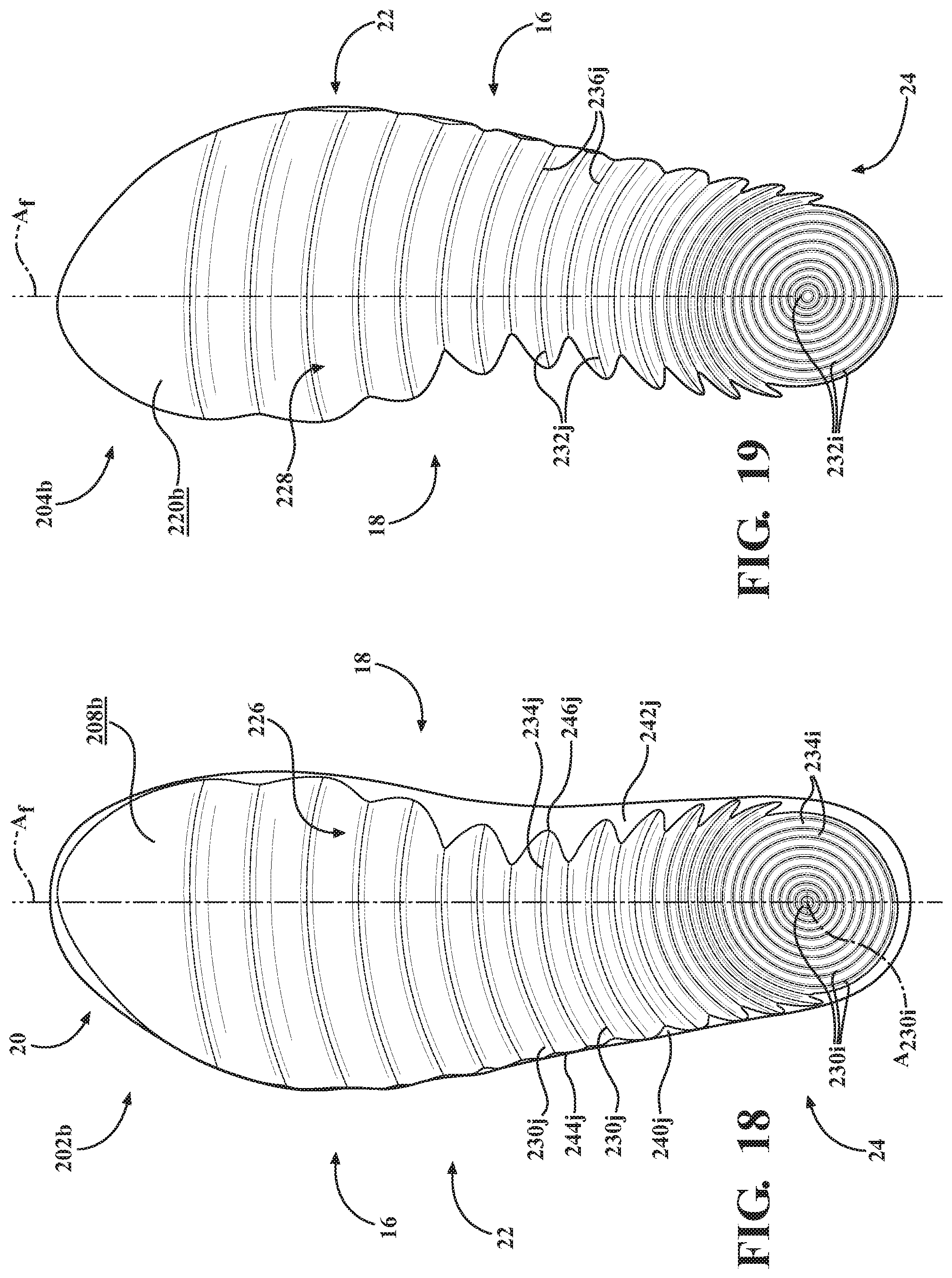
D00017

D00018

D00019

D00020

D00021

D00022

D00023

D00024

D00025
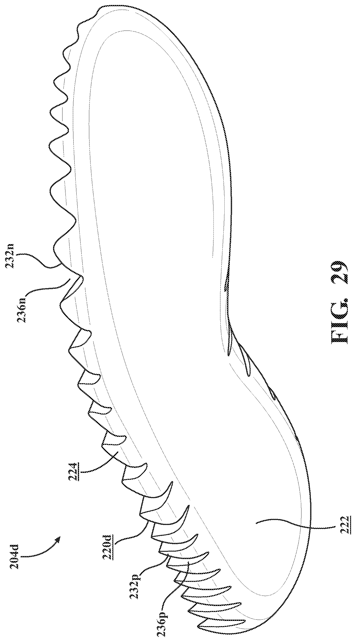
D00026

XML
uspto.report is an independent third-party trademark research tool that is not affiliated, endorsed, or sponsored by the United States Patent and Trademark Office (USPTO) or any other governmental organization. The information provided by uspto.report is based on publicly available data at the time of writing and is intended for informational purposes only.
While we strive to provide accurate and up-to-date information, we do not guarantee the accuracy, completeness, reliability, or suitability of the information displayed on this site. The use of this site is at your own risk. Any reliance you place on such information is therefore strictly at your own risk.
All official trademark data, including owner information, should be verified by visiting the official USPTO website at www.uspto.gov. This site is not intended to replace professional legal advice and should not be used as a substitute for consulting with a legal professional who is knowledgeable about trademark law.