Method For Three-dimensional Human Pose Estimation
Kong; Dehui ; et al.
U.S. patent application number 16/724608 was filed with the patent office on 2020-09-24 for method for three-dimensional human pose estimation. This patent application is currently assigned to Beijing University of Technology. The applicant listed for this patent is Beijing University of Technology. Invention is credited to Dehui Kong, Jinghua Li, Lichun Wang, Shaofan Wang, Yongpeng Wu.
| Application Number | 20200302621 16/724608 |
| Document ID | / |
| Family ID | 1000004576150 |
| Filed Date | 2020-09-24 |


View All Diagrams
| United States Patent Application | 20200302621 |
| Kind Code | A1 |
| Kong; Dehui ; et al. | September 24, 2020 |
METHOD FOR THREE-DIMENSIONAL HUMAN POSE ESTIMATION
Abstract
The invention discloses a method for three-dimensional human pose estimation, which can realize the real-time and high-precision 3D human pose estimation without high configuration hardware support and precise human body model. In this method for three-dimensional human pose estimation, including the following steps: (1) establishing a three-dimensional human body model matching the object, which is a cloud point human body model of visible spherical distribution constraint. (2) Matching and optimizing between human body model for human body pose tracking and depth point cloud. (3) Recovering for pose tracking error based on dynamic database retrieval.
| Inventors: | Kong; Dehui; (Beijing, CN) ; Wu; Yongpeng; (Beijing, CN) ; Wang; Shaofan; (Beijing, CN) ; Li; Jinghua; (Beijing, CN) ; Wang; Lichun; (Beijing, CN) | ||||||||||
| Applicant: |
|
||||||||||
|---|---|---|---|---|---|---|---|---|---|---|---|
| Assignee: | Beijing University of
Technology Beijing CN |
||||||||||
| Family ID: | 1000004576150 | ||||||||||
| Appl. No.: | 16/724608 | ||||||||||
| Filed: | December 23, 2019 |
| Current U.S. Class: | 1/1 |
| Current CPC Class: | G06T 2200/08 20130101; G06T 19/003 20130101; G06T 7/215 20170101; G06T 7/75 20170101; G06T 2207/30196 20130101; G06T 2207/10028 20130101; G06T 7/251 20170101; G06T 2200/04 20130101 |
| International Class: | G06T 7/246 20060101 G06T007/246; G06T 7/215 20060101 G06T007/215; G06T 7/73 20060101 G06T007/73; G06T 19/00 20060101 G06T019/00 |
Foreign Application Data
| Date | Code | Application Number |
|---|---|---|
| Mar 18, 2019 | CN | 201910201559.3 |
Claims
1. A method for three-dimensional human pose estimation, including the following steps: (1) establishing a three-dimensional human body model matching the object, which is a cloud point human body model of visible spherical distribution constraint. (2) Matching and optimizing between human body model for human body pose tracking and depth point cloud. (3) Recovering for pose tracking error based on dynamic database retrieval.
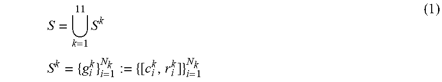
2. The method for three-dimensional human pose estimation according to the claim 1, in step (1): Representation of human body surface with 57 spherical sets. Each sphere is characterized by a radium and a center, which are initialized empirically. By corresponding all the spheres to 11 body components, we define the sphere set S to be the collection of 11 component sphere set models, each of which represents a body component. That is, S = 11 k = 1 S k S k = { g i k } i = 1 N k := { [ c i k , r i k ] ) i = 1 N k ( 1 ) ##EQU00017## Where c.sub.i.sup.k, r.sub.ik represent the center, the radius of the ith sphere in the kth component, respectively, and N.sub.k represents the number of spheres contained in the kth component, with k - 1 1 1 N k = 5 7 . ##EQU00018##
3. The method for three-dimensional human pose estimation according to the claim 2, in step (1), ignore wrist and ankle movements.
4. The method for three-dimensional human pose estimation according to the claim 3, in step (1), for all 57 spheres, we construct a directed tree, each node of which corresponds to a sphere. The root of the tree is g.sub.1.sup.1, and each of the other nodes has a unique parent node which is denoted by a black sphere. The definition of the parent nodes is given by: parent(S.sup.1)=g.sub.1.sup.1,parent(S.sup.2)=g.sub.1.sup.1,parent(S- .sup.3)=g.sub.2.sup.2,parent(S.sup.4)=g.sub.1.sup.3,parent(S.sup.5)=g.sub.- 1.sup.2,parent(S.sup.6)=g.sub.1.sup.5,parent(S.sup.7)=g.sub.2.sup.2,parent- (S.sup.8)=g.sub.2.sup.1,parent(S.sup.9)=g.sub.1.sup.8,parent(S.sup.10)=g.s- ub.2.sup.1,parent(S.sup.11)=g.sub.1.sup.10 (2) Based on this definition, the motion of each body part is considered to be determined by the rotation motion R.sub.k in the local coordinate system with its parent node as the origin plus the global translation vector t in the world coordinate system. Using Fibonacci spherical algorithm to get spherical point cloud by dense sampling, a cloud point human body model of visible spherical distribution constraint is the formula (3): V = 11 k = 1 v k := 11 k = 1 N k i = 1 Q k , i j = 1 { c i k + r i k d k , i j } d k , i j = [ x k , i j , y k , i j , z k , i j ] r x k , i j = 1 - ( z k , i j ) 2 cos ( 2 .pi. j .phi. ) y k , i j = 1 - ( z k , i j ) 2 sin ( 2 .pi. j .phi. ) z k , i j = ( 2 j - 1 ) / N i - 1 ( 3 ) ##EQU00019## Where Q.sub.k,i denotes the number of sampling points of the ith sphere of the kth component, and .PHI..apprxeq.0.618 is the golden section ratio. For example, d.sub.k,i.sup.j denotes the direction vector of the jth sampling point of the ith sphere of the kth component. Therefore, each point is assigned a visibility attribute, which is determined by the observation coordinate system of the point cloud, and whether each point is visible through visibility. detection. A point set consisting of all spherical visible points is used to represent the human body model. It is a cloud point human body model of visible spherical distribution constraint.
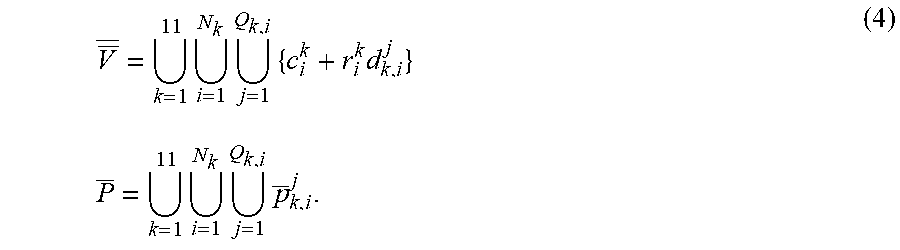
5. The method for three-dimensional human pose estimation according to claim 4, in step (2), the depth point cloud P transformed from the depth map is sampled to obtain P. Assuming that both the model and the depth point cloud are in the same camera coordinate system, The camera corresponding to the depth point cloud is used to constrain the angle of view, and the intersecting part and the occluding part are removed to retain the visible points V on the model under the current angle of view. These points represent the model in the current pose. Using Euclidean distance measure to get P the corresponding point V on V, redefining V: V _ _ = 11 k = 1 N k i = 1 Q k , i j = 1 { c i k + r i k d k , i j } P _ = 11 k = 1 N k i = 1 Q k , i j = 1 p _ k , i j . ( 4 ) ##EQU00020##
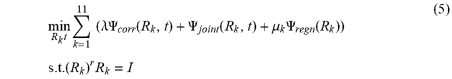
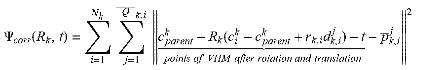
6. The method for three-dimensional human pose estimation according to claim 5, in step (2), After the correspondence between P and V is established, the movement of human body as a series of simultaneous and slow movements of all body component. Therefore, the matching and optimization of the model and point cloud convert a global translation t and a series of local rotation. Cost function is formula (5): min R k t k = 1 11 ( .lamda. .PSI. corr ( R k , t ) + .PSI. joint ( R k , t ) + .mu. k .PSI. regn ( R k ) ) s . t . ( R k ) r R k = I ( 5 ) ##EQU00021## Where .lamda., .mu..sub.k>0 and are weight parameters, the first term .PSI..sub.corr penalizes the distance between model surface point and input depth point cloud, .PSI. corr ( R k , t ) = i = 1 N k j = 1 Q _ k , i c parent k + R k ( c i k - c parent k + r k , i d k , i j ) + t points of VHM after rotation and translation - p _ k , i j 2 ##EQU00022## Where c.sub.parent.sup.k represents the center coordinate of the parent node of kth component. Based on this constraint, each point of the model is enforced to locate closer to the corresponding point cloud after rotation and translation. The second term .PSI..sub.joint is formula (6), using the joint position information and position direction information of the previous frame, it is used as a special marker information to restrict the excessive space movement and position rotation between the two frames, and to reduce the difference between the two frames to a certain extent .PSI..sub.joint(R.sub.k,t)=.SIGMA..sub.m=1.sup.M.sup.k(.alpha..sub.k,m.pa- rallel.j.sub.k,m+t-j.sub.k,m.sup.init.parallel..sup.2+.beta..sub.k,m.paral- lel.R.sub.kn.sub.k,m-n.sub.k,m.sup.init.parallel..sup.2 (6) Where j.sub.k,m, j.sub.k,m.sup.init represent the position of the mth joint of the kth component under current pose and initial pose, respectively. n.sub.k,m, n.sub.k,m.sup.init represent the position of the mth joint and its parent joint under current pose and initial pose, respectively. The weight .alpha..sub.k,m, .beta..sub.k,m for balancing the correspondence term and location is formula (7): .alpha. k , m = .tau. k 1 + e - ( j k , m - j k , m init - .omega. 2 ) .beta. k , m = .gamma. k 1 + e - ( arccos ( n k , m r n k , m init ) - .omega. 2 ) ( 7 ) ##EQU00023## Where .omega..sub.2, .omega..sub.3>0, and are weight parameters for controlling the range of error. .tau..sup.k,.gamma..sup.k are scaling parameters which defined by: .tau. k = .mu. 1 1 + e ( Dist ( P _ k , V _ _ k ) - .omega. 2 ) .gamma. k = .mu. 2 1 + e ( Dist ( P _ k , V _ _ k ) - .omega. 2 ) Dist ( P _ k , V _ _ k ) = 1 P _ k k = 1 11 i = 1 N k j = 1 Q k , i c i k + r i k d k , i j - p _ k , i j ( 8 ) ##EQU00024## Where Dist(P.sup.k, V.sup.k) represents the average distance between corresponding points of P.sup.k,V.sup.k. .omega..sub.1>0 is used to determine the distance error threshold. .tau..sup.k,.gamma..sup.k are only solved before optimization and after the first corresponding relationship is determined, and remains unchanged in the iterative process. .alpha..sub.k,m,.beta..sub.k,n, update when updating correspondence. The third term .PSI..sub.regu is formula (9). The large rotation of each part in the iterative process is constrained. The motion between two adjacent frames is regarded as the process of simultaneous change of each part .PSI..sub.ragu(R.sub.k)=.parallel.R.sub.k-I.parallel..sup.2 (9).
7. The method for three-dimensional human pose estimation according to claim 6, in step (3), Using the overlap rate .theta..sub.overlap and cost function value .theta..sub.cost of the input depth point cloud and the constructed human body model on the two-dimensional plane to determine whether the current tracking fails. Assuming that human limb motion segments have the repetitive characteristics in time series, the direction information of each body part is used to represent human three-dimensional motion, the upper and lower trunk parts are simplified into two mutually perpendicular main directions, each part of the limbs is represented by a direction vector, and the direction of the head is ignored, which is expressed as a formula (10): v=(v.sub.1.sup.r, . . . ,v.sub.10.sup.r).sup.r (10) Where v.sub.1,v.sub.2 correspond to the pairwise perpendicular unit directions of upper torso, lower torso, respectively, and v.sub.3, . . . , v.sub.10 correspond to the unit direction of all components except upper torso, lower torso, head.
8. The method for three-dimensional human pose estimation according to claim 7, in step (3), PCA is used to extract the main direction [e.sub.1, e.sub.2, e.sub.3] of the depth point cloud, and the minimum bounding box [w,d,h] of the main direction is used to represent the characteristics of the depth point cloud, which is formula (11): e=(we.sub.1.sup.r,de.sub.1.sup.r,he.sub.5.sup.r).sup.r (11) If the cost function of matching is less than the threshold value in the tracking process .theta..sub.overlap.ltoreq..theta..sub.1 and .theta..sub.cost.ltoreq..theta..sub.2, the tracking is successful and update the database model D by extracting feature s [e,v]. The extracted characteristics [e,v] are saved in database as a pair of characteristic vectors. When the tracking fails, the Euclidean distance is calculated by using the characteristics e of the corresponding depth point cloud in the database, the first five positions {[e.sup.(i), v.sup.(i)]}.sub.i=1.sup.5 with the smallest distance are found in the database, and the position with the highest overlap rate with the current input depth point cloud is retrieved by using v.sup.(i), i=1, . . . , 5 to recover the visible spherical distribution constraint point cloud manikin, so as to facilitate the recovery from the tracking failure.
Description
CROSS REFERENCE TO THE RELATED APPLICATIONS
[0001] This application is based upon and claims priority to Chinese Patent Application No. CN 201910201559.3, filed on Mar. 18, 2019, the entire contents of which are incorporated herein by reference.
TECHNICAL FIELD
[0002] The present invention relates to the technical field of computer vision and pattern recognition, and particularly to a method for three-dimensional human pose estimation.
BACKGROUND OF THE INVENTION
[0003] Three-dimensional (3D) human pose estimation based on computer vision technology has been widely used in many fields of human life, such as computer animation, medicine, human-computer interaction and so on. With the introduction of low-cost RGB-D sensors (such as Kinect), compared with RGB visual information, depth image can greatly avoid data defects caused by complex background and changes in light conditions. Therefore, the performance of 3D human pose estimation is improved obviously by using the depth information, which has become the current research hotspot. At present, many methods of 3D human pose estimation based on depth data have achieved better recognition results, but the further improvement of recognition accuracy still needs to overcome two inherent serious defects of depth data acquired by sensors: noise and occlusion.
[0004] There are two kinds of methods for 3D human pose estimation based on depth information: discriminant method and generating method. The former relies on a large number of training data, and therefore can adapt to the changes of different body types, but most of them can not get higher precision in the case of complex motion; the latter usually depends on complex and accurate human body model, and therefore can get high precision in the case of data loss, but in the case of fast and complex motion, it is easy to fall into local optimization and lose the global optimum solution. It can be seen that the implementation of high-performance 3D human pose estimation methods often depends on the following points: 1) a large number of accurate training data sets; 2) a huge pose database for tracking error recovery; 3) GPU acceleration support; 4) accurate 3D human model. These limitations limit the application of real-time human-computer interaction on the platform of general hardware configuration.
SUMMARY
[0005] The technical problem addressed by the present invention is to overcome the deficiency in the prior art, and to provide a method for three-dimensional human pose estimation, which can realize the real-time and high-precision 3D human pose estimation without high configuration hardware support and precise human body model.
[0006] The technical solution of the present invention is that, in this method for three-dimensional human pose estimation, including the following steps: [0007] (1) establishing a three-dimensional human body model matching the object, which is a cloud point human body model of visible spherical distribution constraint. [0008] (2) Matching and optimizing between human body model for human body pose tracking and depth point cloud. [0009] (3) Recovering for pose tracking error based on dynamic database retrieval.
[0010] The invention takes the depth map sequence as the input, optimizes and matches with the established 3D human body model and the 3D point cloud transformed from the depth map. The optimization process combines the global translation transformation and the local rotation transformation, and uses the dynamic database to recover the pose when the tracking error occurs, finally realizes the fast and accurate pose tracking, and obtains the estimated position of the joint points from the human body model. So the real-time and high-precision three-dimensional human pose estimation can be realized without high configuration hardware support and accurate human body model.
BRIEF DESCRIPTION OF THE DRAWINGS
[0011] FIG. 1 shows that the ball set represents the human body model and the spherical point set represents the human body model. FIG. 1a shows the ball set represents the human body model and the division of parts, and FIG. 1b shows the surface sampling of the ball set.
[0012] FIG. 2 shows 11 parts naming and parts parent node division diagram of human body. FIG. 2a shows 11 parts division and naming, and FIG. 2b shows parts parent node division.
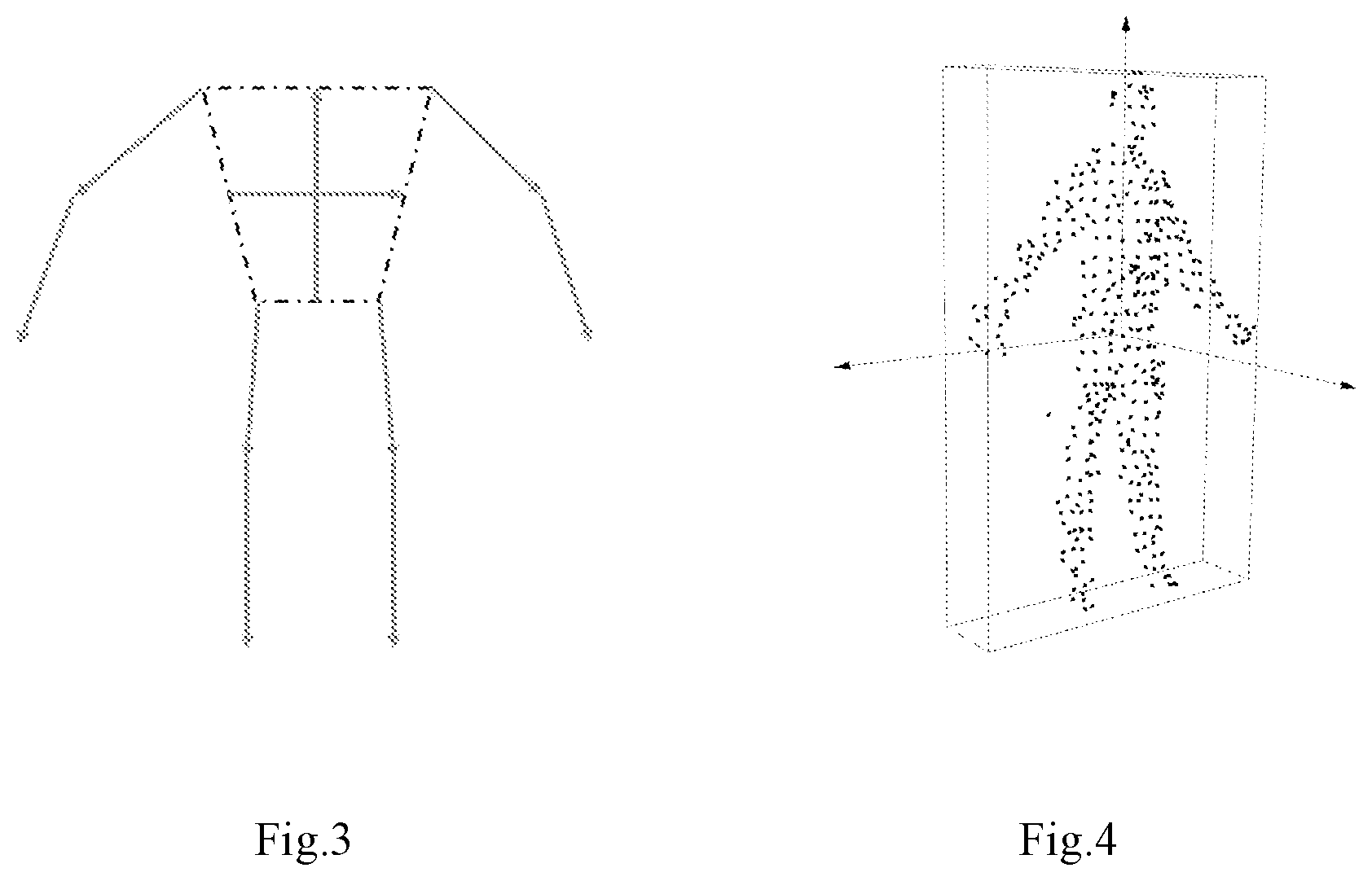
[0013] FIG. 3 shows the representation of human body direction characteristic.
[0014] FIG. 4 shows the minimum bounding box construction based on PCA main direction.
[0015] FIG. 5 shows the average error of the SMMC dataset.
[0016] FIG. 6 shows the PDT dataset mean error.
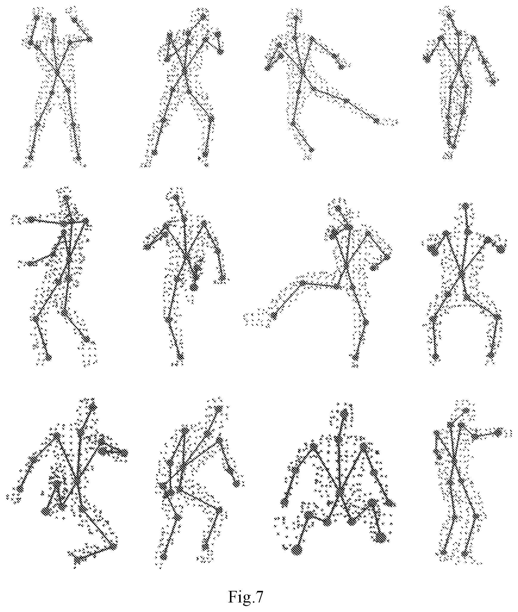
[0017] FIG. 7 shows the subjective effect display on the PDT database.
[0018] FIG. 8 shows a flow chart of the three-dimensional human pose estimation method according to the present invention.
DETAILED DESCRIPTION OF THE EMBODIMENTS
[0019] As shown as FIG. 8, in this method for three-dimensional human pose estimation, including the following steps: [0020] (1) establishing a three-dimensional human body model matching the object, which is a cloud point human body model of visible spherical distribution constraint. [0021] (2) Matching and optimizing between human body model for human body pose tracking and depth point cloud. [0022] (3) Recovering for pose tracking error based on dynamic database retrieval.
[0023] The invention takes the depth map sequence as the input, optimizes and matches with the established 3D human body model and the 3D point cloud transformed from the depth map. The optimization process combines the global translation transformation and the local rotation transformation, and uses the dynamic database to recover the pose when the tracking error occurs, finally realizes the fast and accurate pose tracking, and obtains the estimated position of the joint points from the human body model. So the real-time and high-precision three-dimensional human pose estimation can be realized without high configuration hardware support and accurate human body model.
[0024] Preferably, in step (1):
[0025] Representation of human body surface with 57 spherical sets. Each sphere is characterized by a radium and a center, which are initialized empirically. By corresponding all the spheres to 11 body components, we define the sphere set S to be the collection of 11 component sphere set models, each of which represents a body component. That is,
S = 11 k = 1 S k S k = { g i k } i = 1 N k := { [ c i k , r i k ] } i = 1 N k ( 1 ) ##EQU00001##
Where c.sub.i.sup.k,r.sub.i.sup.k represent the center, the radius of the ith sphere in the kth component, respectively, and N.sub.k represents the number of spheres contained in the kth component, with
k = 1 11 N k = 57. ##EQU00002##
[0026] Preferably, in step (1), ignore wrist and ankle movements.
[0027] Preferably, in step (1), for all 57 spheres, we construct a directed tree, each node of which corresponds to a sphere. The root of the tree is g.sub.1.sup.1, and each of the other nodes has a unique parent node which is denoted by a black sphere. The definition of the parent nodes is given by:
parent(S.sup.1)=g.sub.1.sup.1,parent(S.sup.2)=g.sub.1.sup.1,parent(S.sup- .3)=g.sub.2.sup.2,parent(S.sup.4=g.sub.1.sup.3,parent(S.sup.5)=g.sub.1.sup- .2,parent(S.sup.6)=g.sub.1.sup.5,parent(S.sup.7)=g.sub.2.sup.2,parent(S.su- p.8)=g.sub.8.sup.1,parent(S.sub.9)=g.sub.1.sup.8,parent(S.sup.10)=g.sub.2.- sup.1,parent(S.sup.11)=g.sub.1.sup.10 (2)
[0028] Based on this definition, the motion of each body part is considered to be determined by the rotation motion R.sub.k in the local coordinate system with its parent node as the origin plus the global translation vector t in the world coordinate system. Using Fibonacci spherical algorithm to get spherical point cloud by dense sampling, a cloud point human body model of visible spherical distribution constraint is the formula (3):
V = 11 k = 1 V k := 11 k = 1 N k i = 1 Q k , i j = 1 { c i k + r i k d k , i j } d k , i j = [ x k , i j , y k , i j z k , i j ] T x k , i j = 1 - ( z k , i j ) 2 cos ( 2 .pi. j .phi. ) y k , i j = 1 - ( z k , i j ) 2 sin ( 2 .pi. j .phi. ) z k , i j = ( 2 j - 1 ) / N i - 1 ( 3 ) ##EQU00003##
[0029] Where Q.sub.k,i denotes the number of sampling points of the ith sphere of the kth component, and .PHI..apprxeq.0.618 is the golden section ratio. For example, d.sub.k,i.sup.j denotes the direction vector of the jth sampling point of the ith sphere of the kth component. Therefore, each point is assigned a visibility attribute, which is determined by the observation coordinate system of the point cloud, and whether each point is visible through visibility. detection. A point set consisting of all spherical visible points is used to represent the human body model. It is a cloud point human body model of visible spherical distribution constraint.
[0030] Preferably, in step (2), the depth point cloud P transformed from the depth map is sampled to obtain P. Assuming that both the model and the depth point cloud are in the same camera coordinate system, The camera corresponding to the depth point cloud is used to constrain the angle of view, and the intersecting part and the occluding part are removed to retain the visible points V on the model under the current angle of view. These points represent the model in the current pose. Using Euclidean distance measure to get P the corresponding point V on v, redefining V:
V _ _ = 11 k = 1 N k i = 1 Q k , i j = 1 { c i k + r i k d k , i j } P _ = 11 k = 1 N k i = 1 Q k , i j = 1 p _ k , i j . ( 4 ) ##EQU00004##
[0031] Preferably, in step (2),
[0032] After the correspondence between P and V is established, the movement of human body as a series of simultaneous and slow movements of all body component. Therefore, the matching and optimization of the model and point cloud convert a global translation t and a series of local rotation. Cost function is formula (5):
min R k , t k = 1 11 ( .lamda. .PSI. corr ( R k , t ) + .PSI. joint ( R k , t ) + .mu. k .PSI. regn ( R k ) ) s . t . ( R k ) T R k = I ( 5 ) ##EQU00005##
[0033] Where .lamda., .mu..sub.k>0 and are weight parameters, the first term .PSI..sub.corr penalizes the distance between model surface point and input depth point cloud,
.PSI. corr ( R k , t ) = i = 1 N k j = 1 Q _ k , i c parent k + R k ( c i k - c parent k + r k , i d k , i j ) + t points of VHM after rotation and translation - p _ k , i j 2 ##EQU00006##
[0034] Where c.sub.parent.sup.k represents the center coordinate of the parent node of kth component. Based on this constraint, each point of the model is enforced to locate closer to the corresponding point cloud after rotation and translation. The second term .PSI..sub.joint is formula (6), using the joint position information and position direction information of the previous frame, it is used as a special marker information to restrict the excessive space movement and position rotation between the two frames, and to reduce the difference between the two frames to a certain extent
.PSI..sub.joint(R.sub.k,t)=.SIGMA..sub.m=1.sup.M.sup.k(.alpha..sub.k,m.p- arallel.j.sub.k,m+t-j.sub.k,m.sup.init.parallel..sup.2+.beta..sub.k,m.para- llel.R.sub.kn.sub.k,m-n.sub.k,m.sup.init.parallel..sup.2 (6)
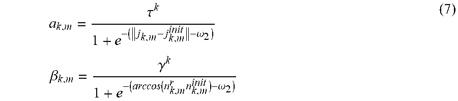
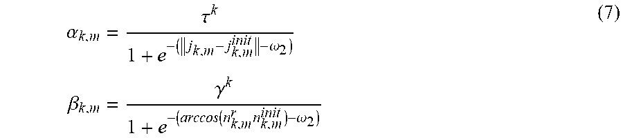
[0035] Where j.sub.k,m,j.sub.k,m.sup.init represent the position of the mth joint of the kth component under current pose and initial pose, respectively. n.sub.k,m, n.sub.k,m.sup.init, represent the position of the mth joint and its parent joint under current pose and initial pose, respectively. The weight .alpha..sub.k,m, .beta..sub.k,m for balancing the correspondence term and location is formula (7):
a k , m = .tau. k 1 + e - ( j k , m - j k , m init - .omega. 2 ) .beta. k , m = .gamma. k 1 + e - ( arccos ( n k , m r n k , m init ) - .omega. 2 ) ( 7 ) ##EQU00007##
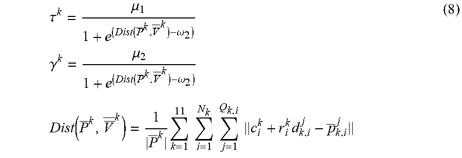
[0036] Where .omega..sub.2,.omega..sub.3, >0, and are weight parameters for controlling the range of error. .tau..sup.k,.gamma..sup.k are scaling parameters which defined by:
.tau. k = .mu. 1 1 + e ( Dist ( P _ k , V _ _ k ) - .omega. 2 ) .gamma. k = .mu. 2 1 + e ( Dist ( P _ k , V _ _ k ) - .omega. 2 ) Dist ( P _ k , V _ _ k ) = 1 P _ k k = 1 11 i = 1 N k j = 1 Q k , i c i k + r i k d k , i j - p _ k , i j ( 8 ) ##EQU00008##
[0037] Where Dist(P.sup.k, V.sup.k) represents the average distance between corresponding points of P.sup.k,V.sup.k. .omega..sub.1>0 is used to determine the distance error threshold. .tau..sup.k,.gamma..sup.k are only solved before optimization and after the first corresponding relationship is determined, and remains unchanged in the iterative process. .alpha..sub.k,m,.beta..sub.k,m update when updating correspondence.
[0038] The third term .PSI..sub.regu is formula (9). The large rotation of each part in the iterative process is constrained. The motion between two adjacent frames is regarded as the process of simultaneous change of each part
.PSI..sub.regu(R.sub.k)=.parallel.R.sub.k-I.parallel..sup.2(9).
[0039] Preferably, in step (3),
[0040] Using the overlap rate .theta..sub.overlap and cost function value .theta..sub.cost of the input depth point cloud and the constructed human body model on the two-dimensional plane to determine whether the current tracking fails. Assuming that human limb motion segments have the repetitive characteristics in time series, the direction information of each body part is used to represent human three-dimensional motion, the upper and lower trunk parts are simplified into two mutually perpendicular main directions, each part of the limbs is represented by a direction vector, and the direction of the head is ignored, which is expressed as a formula (10):
v=(v.sub.1.sup.r, . . . v.sub.10.sup.r).sup.r (10)
[0041] Where v.sub.1, v.sub.2 correspond to the pairwise perpendicular unit directions of upper torso, lower torso, respectively, and v.sub.3, . . . , v.sub.10 correspond to the unit direction of all components except upper torso, lower torso, head.
[0042] Preferably, in step (3),
[0043] PCA is used to extract the main direction [e.sub.1, e.sub.2, e.sub.3] of the depth point cloud, and the minimum bounding box [w,d,h] of the main direction is used to represent the characteristics of the depth point cloud, which is formula (11):
e=(we.sub.1.sup.r,de.sub.1.sup.r,he.sub.3.sup.r).sup.r (11)
[0044] If the cost function of matching is less than the threshold value in the tracking process .theta..sub.overlap.ltoreq..theta..sub.1 and .theta..sub.cost.ltoreq..theta..sub.2, the tracking is successful and update the database model D by extracting feature s [e,v]. The extracted characteristics [e,v] are saved in database as a pair of characteristic vectors. When the tracking fails, the Euclidean distance is calculated by using the characteristics e of the corresponding depth point cloud in the database, the first five positions {[e.sup.(i), v.sup.(i)]}.sub.i=1.sup.5 with the smallest distance are found in the database, and the position with the highest overlap rate with the current input depth point cloud is retrieved by using v.sup.(i), i=1, . . . , 5 to recover the visible spherical distribution constraint point cloud manikin, so as to facilitate the recovery from the tracking failure.
[0045] The invention is described in more detail below.
[0046] The invention takes the depth map sequence as the input, optimizes the matching between the established 3D human body model and the 3D point cloud transformed from the depth map. The optimization process combines the global translation transformation and the local rotation transformation, and uses the dynamic database to recover the pose when the tracking error occurs, finally realizes the fast and accurate pose tracking, and obtains the estimated joint position from the human body model. The invention mainly includes three key technical points: (1) establishing a three-dimensional human body model matching the object, which combines the advantages of geometric model and mesh model. (2) On the basis of the model, the matching optimization problem between the human body model and the point cloud is transformed into solving the global translation transformation matrix and the local rotation transformation matrix based on the determination of the corresponding relationship between the human body model and the depth point cloud. (3) Building a small dynamic database to track reinitialization in case of failure.
[0047] 1. A cloud point human body model of visible spherical distribution constraint:
[0048] As shown as FIG. 1a, representation of human body surface with 57 spherical sets. Each sphere is characterized by a radium and a center, which are initialized empirically. As shown as FIG. 2a, by corresponding all the spheres to 11 body components, we define the sphere set S to be the collection of 11 component sphere set models, each of which represents a body component. That is,
S = 11 k = 1 S k S k = { g i k } i = 1 N k := { [ c i k , r i k ] } i = 1 N k ( 1 ) ##EQU00009##
[0049] Where c.sub.i.sup.k, r.sub.i.sup.k represent the center, the radius of the ith sphere in the kth component, respectively, and N.sub.k represents the number of spheres contained in the kth component, with
S = 11 k = 1 S k S k = { g i k } i = 1 N k := { [ c i k , r i k ] ) i = 1 N k ( 1 ) ##EQU00010##
For simplification, ignore wrist and ankle movements.
[0050] For all 57 spheres, we construct a directed tree, each node of which corresponds to a sphere, as shown as FIG. 2b. The root of the tree is g.sub.1.sup.1, and each of the other nodes has a unique parent node which is denoted by a black sphere. The definition of the parent nodes is given by:
parent(S.sup.1)=g.sub.1.sup.1,parent(S.sup.2)=g.sub.1.sup.1,parent(S.sup- .3)=g.sub.3.sup.2,parent(S.sup.4=g.sub.1.sup.3,parent(S.sup.5)=g.sub.1.sup- .2,parent(S.sup.6)=g.sub.1.sup.5,parent(S.sup.7)=g.sub.2.sup.2,parent(S.su- p.8)=g.sub.z.sup.1,parent(S.sup.9)=g.sub.1.sup.8,parent(S.sup.10)=g.sub.2.- sup.1,parent(S.sup.11)=g.sub.1.sup.10 (2)
[0051] Based on this definition, the motion of each body part is considered to be determined by the rotation motion R.sub.k in the local coordinate system with its parent node as the origin plus the global translation vector t in the world coordinate system. FIG. 1b shows the surface sampling of the ball set. Using Fibonacci spherical algorithm to get spherical point cloud by dense sampling, a cloud point human body model of visible spherical distribution constraint is the formula (3):
V = 11 k = 1 v k := 11 k = 1 N k i = 1 Q k , i j = 1 { c i k + r i k d k , i j } d k , i j = [ x k , i j , y k , i j , z k , i j ] r x k , i j = 1 - ( z k , i j ) 2 cos ( 2 .pi. j .phi. ) y k , i j = 1 - ( z k , i j ) 2 sin ( 2 .pi. j .phi. ) z k , i j = ( 2 j - 1 ) / N i - 1 ( 3 ) ##EQU00011##
[0052] Where Q.sub.k,i denotes the number of sampling points of the ith sphere of the kth component, and .PHI..apprxeq.0.618 is the golden section ratio. For example, d.sub.k,i.sup.j denotes the direction vector of the jth sampling point of the ith sphere of the kth component. Therefore, each point is assigned a visibility attribute, which is determined by the observation coordinate system of the point cloud, and whether each point is visible through visibility. detection. A point set consisting of all spherical visible points is used to represent the human body model. It is a cloud point human body model of visible spherical distribution constraint. At this time, the model can not only control the shape of human body conveniently by changing the parameters of sphere definition, but also accurately represent the human body's pose by optimizing and matching with the input point cloud.
[0053] 2. Matching and optimizing between human body model for human body pose tracking and depth point cloud
[0054] The depth point cloud P transformed from the depth map is sampled to obtain P. Assuming that both the model and the depth point cloud are in the same camera coordinate system, The camera corresponding to the depth point cloud is used to constrain the angle of view, and the intersecting part and the occluding part are removed to retain the visible points V on the model under the current angle of view. These points represent the model in the current pose. Using Euclidean distance measure to get P. the corresponding point V on V, redefining V:
V _ _ = 11 k = 1 N k i = 1 Q k , i j = 1 { c i k + r i k d k , i j } P _ = 11 k = 1 N k i = 1 Q k , i j = 1 p _ k , i j . ( 4 ) ##EQU00012##
[0055] After the correspondence between P and V is established, the movement of human body as a series of simultaneous and slow movements of all body component. Therefore, the matching and optimization of the model and point cloud convert a global translation t and a series of local rotation. Cost function is formula (5):
min R k t k = 1 11 ( .lamda. .PSI. corr ( R k , t ) + .PSI. joint ( R k , t ) + .mu. k .PSI. regn ( R k ) ) s . t . ( R k ) r R k = I ( 5 ) ##EQU00013##
[0056] Where .lamda., .mu..sub.k>0 and are weight parameters, the first term .PSI..sub.corr penalizes the distance between model surface point and input depth point cloud,
.PSI. corr ( R k , t ) = i = 1 N k j = 1 Q _ k , i c parent k + R k ( c i k - c parent k + r k , i d k , i j ) + t points of VHM after rotation and translation - p _ k , i j 2 ##EQU00014##
[0057] Where c.sub.parent.sup.k represents the center coordinate of the parent node of kth component. Based on this constraint, each point of the model is enforced to locate closer to the corresponding point cloud after rotation and translation. The second term .PSI..sub.joint is formula (6), using the joint position information and position direction information of the previous frame, it is used as a special marker information to restrict the excessive space movement and position rotation between the two frames, and to reduce the difference between the two frames to a certain extent
.PSI..sub.joint(R.sub.k,t)=.SIGMA..sub.m=1.sup.M.sup.6(.alpha..sub.k,m.p- arallel.j.sub.k,m+t-j.sub.k,m.sup.init.parallel..sup.2+.beta..sub.k,m.para- llel.R.sub.kn.sub.k,m-n.sub.k,m.sup.init.parallel..sup.2 (6)
[0058] Where j.sub.k,m, j.sub.k,m.sup.init, represent the position of the mth joint of the kth component under current pose and initial pose, respectively. n.sub.k,m,n.sub.k,m.sup.init, represent the position of the mth joint and its parent joint under current pose and initial pose, respectively. The weight .alpha..sub.k,m, .beta..sub.k,m for balancing the correspondence term and location is formula (7):
.alpha. k , m = .tau. k 1 + e - ( j k , m - j k , m init - .omega. 2 ) .beta. k , m = .gamma. k 1 + e - ( arccos ( n k , m r n k , m init ) - .omega. 2 ) ( 7 ) ##EQU00015##
[0059] Where .omega..sub.2, .omega..sub.3>0, and are weight parameters for controlling the range of error. .tau..sup.k,.gamma..sup.k are scaling parameters which defined by:
.tau. k = .mu. 1 1 + e ( Dist ( P _ k , V _ _ k ) - .omega. 2 ) .gamma. k = .mu. 2 1 + e ( Dist ( P _ k , V _ _ k ) - .omega. 2 ) Dist ( P _ k , V _ _ k ) = 1 P _ k k = 1 11 i = 1 N k j = 1 Q k , i c i k + r i k d k , i j - p _ k , i j ( 8 ) ##EQU00016##
[0060] Where Dist(P.sup.k,V.sup.k) represents the average distance between corresponding points of P.sup.k,V.sup.k. .omega..sub.1>0 is used to determine the distance error threshold. .tau..sup.k, .gamma..sup.k are only solved before optimization and after the first corresponding relationship is determined, and remains unchanged in the iterative process. .alpha..sub.k,m, .beta..sub.k,m update when updating correspondence.
[0061] The third term .PSI..sub.regu is formula (9). The large rotation of each part in the iterative process is constrained. The motion between two adjacent frames is regarded as the process of simultaneous change of each part
.PSI..sub.ragu(R.sub.k)=.parallel.R.sub.k-I.parallel..sup.2 (9).
[0062] 3. Recovering for pose tracking error based on dynamic database retrieval
[0063] Since the invention belongs to the unsupervised attitude estimation method, the attitude recovery operation is required when the tracking error occurs. Using the overlap rate .theta..sub.overlap and cost function value .theta..sub.cost of the input depth point cloud and the constructed human body model on the two-dimensional plane to determine whether the current tracking fails. Assuming that human limb motion segments have the repetitive characteristics in time series, therefore, an attitude tracking recovery method based on small dynamic database is proposed. The direction information of each body part is used to represent human three-dimensional motion, as shown as FIG. 3, the upper and lower trunk parts are simplified into two mutually perpendicular main directions, each part of the limbs is represented by a direction vector, and the direction of the head is ignored, which is expressed as a formula (10):
v=(v.sub.1.sup.r, . . . v.sub.10.sup.r).sup.r (10)
[0064] Where v.sub.1, v.sub.2, correspond to the pairwise perpendicular unit directions of upper torso, lower torso, respectively, and v.sub.3, . . . , v.sub.10 correspond to the unit direction of all components except upper torso, lower torso, head.
[0065] As shown as FIG. 4, PCA is used to extract the main direction [e.sub.1, e.sub.2, e.sub.3] of the depth point cloud, and the minimum bounding box [w,d,h] of the main direction is used to represent the characteristics of the depth point cloud, which is formula (11):
e=(we.sub.1.sup.r,de.sub.1.sup.r,he.sub.3.sup.r).sup.r (11)
[0066] If the cost function of matching is less than the threshold value in the tracking process .theta..sub.overlap.ltoreq..theta..sub.1 and .theta..sub.cost.ltoreq..theta..sub.2, the tracking is successful and update the database model D by extracting feature s [e,v]. The extracted characteristics [e,v] are saved in database as a pair of characteristic vectors. When the tracking fails, the Euclidean distance is calculated by using the characteristics e of the corresponding depth point cloud in the database, the first five positions {[e.sup.(i), v.sup.(i)]}.sub.i=1.sup.5 with the smallest distance are found in the database, and the position with the highest overlap rate with the current input depth point cloud is retrieved by using v.sup.(i), i=1, . . . , 5 to recover the visible spherical distribution constraint point cloud manikin, so as to facilitate the recovery from the tracking failure.
[0067] The invention has been verified on the open data set SMMC and PDT data set, and good experimental results have been obtained. FIG. 5 shows the average error of the invention on the SMMC data set. The SMMC data set is relatively simple in operation. It can be seen that our method is equivalent to the result of the best method at present. FIG. 6 shows the average error of the PDT data set of the invention. The action of the PDT data set is complex and challenging, but the method of the invention can also achieve good results. Table 1 shows the efficiency comparison between PDT and SMMC database and other similar methods. Compared with other methods, the average speed of the invention can achieve real-time without GPU acceleration. FIG. 7 shows the subjective effects of some complex postures on the PDT dataset, and the experimental results show that the algorithm can still achieve better estimation results in complex actions.
TABLE-US-00001 TABLE 1 algorithm real-time (Y/N) GPU (Y/N) Ding&Fan N N Ye&Yang Y Y Vasileiadis et al Y Y The invention Y N
[0068] The above contents are only the preferable embodiments of the present invention, and do not limit the present invention in any manner. Any improvements, amendments and alternative changes made to the above embodiments according to the technical spirit of the present invention shall fall within the claimed scope of the present invention.
* * * * *
D00000
D00001
D00002
D00003
D00004
D00005


XML
uspto.report is an independent third-party trademark research tool that is not affiliated, endorsed, or sponsored by the United States Patent and Trademark Office (USPTO) or any other governmental organization. The information provided by uspto.report is based on publicly available data at the time of writing and is intended for informational purposes only.
While we strive to provide accurate and up-to-date information, we do not guarantee the accuracy, completeness, reliability, or suitability of the information displayed on this site. The use of this site is at your own risk. Any reliance you place on such information is therefore strictly at your own risk.
All official trademark data, including owner information, should be verified by visiting the official USPTO website at www.uspto.gov. This site is not intended to replace professional legal advice and should not be used as a substitute for consulting with a legal professional who is knowledgeable about trademark law.