Evaporative Heat Exchange Apparatus With Finned Elliptical Tube Coil Assembly
BUGLER, III; Thomas William ; et al.
U.S. patent application number 16/722199 was filed with the patent office on 2020-09-24 for evaporative heat exchange apparatus with finned elliptical tube coil assembly. The applicant listed for this patent is Evapco, Inc.. Invention is credited to Thomas William BUGLER, III, Davey Joe VADDER.
| Application Number | 20200300548 16/722199 |
| Document ID | / |
| Family ID | 1000004882070 |
| Filed Date | 2020-09-24 |


| United States Patent Application | 20200300548 |
| Kind Code | A1 |
| BUGLER, III; Thomas William ; et al. | September 24, 2020 |
EVAPORATIVE HEAT EXCHANGE APPARATUS WITH FINNED ELLIPTICAL TUBE COIL ASSEMBLY
Abstract
An improved finned coil tube assembly enhances evaporative heat exchanger performance, and includes tubes, preferably serpentine tubes, in the coil assembly. The tubes have a generally elliptical cross-section with external fins formed on an outer surface of the tubes. The fins are spaced substantially 1.5 to substantially 3.5 fins per inch (2.54 cm) along the longitudinal axis of the tubes, extend substantially 23.8% to substantially 36% of the nominal tube outside diameter in height from the tubes outer surface and have a thickness of substantially 0.007 inch (0.018 cm) to substantially 0.020 inch (0.051 cm). The tubes have a center-to-center spacing generally horizontally and normal to the longitudinal axis of the tubes of substantially 109% to substantially 125% of the nominal tube outside diameter, and a generally vertical center-to-center spacing of substantially 100% to about 131% of the nominal tube outside diameter.
| Inventors: | BUGLER, III; Thomas William; (Frederick, MD) ; VADDER; Davey Joe; (Manchester, MD) | ||||||||||
| Applicant: |
|
||||||||||
|---|---|---|---|---|---|---|---|---|---|---|---|
| Family ID: | 1000004882070 | ||||||||||
| Appl. No.: | 16/722199 | ||||||||||
| Filed: | December 20, 2019 |
Related U.S. Patent Documents
| Application Number | Filing Date | Patent Number | ||
|---|---|---|---|---|
| 15622729 | Jun 14, 2017 | |||
| 16722199 | ||||
| 12838003 | Jul 16, 2010 | |||
| 15622729 | ||||
| Current U.S. Class: | 1/1 |
| Current CPC Class: | F28F 1/02 20130101; F28F 1/30 20130101; F28D 5/02 20130101; F28F 1/36 20130101 |
| International Class: | F28D 5/02 20060101 F28D005/02; F28F 1/02 20060101 F28F001/02; F28F 1/30 20060101 F28F001/30; F28F 1/36 20060101 F28F001/36 |
Claims
1-37. (canceled)
38. An evaporative indirect heat exchanger comprising: a plenum having a generally vertical axis, a coil assembly, a distributor for distributing an external heat exchange liquid onto a coil assembly, an air mover for causing air to flow in a direction through the plenum, and said coil assembly mounted within the plenum such that the external heat exchange liquid flows externally through the coil assembly in a generally downward vertical flow direction, and the air flows externally through the coil assembly interacting with the external heat exchange liquid to evaporate and cool the external heat exchange liquid and internal process fluid within the coil assembly, wherein the coil assembly comprises inlet and outlet manifolds and a plurality of tubes connecting the manifolds, each tube comprising a plurality of horizontally oriented segments arranged vertically relative to one-another in a single vertical plane, wherein each segment has a longitudinal axis and a generally elliptical cross-sectional shape having a major axis and a minor axis where the average of the major axis length and the minor axis length is a nominal tube outside diameter, and where the major axis of each segment of a tube is aligned with the single vertical plane, wherein the tubes are arranged in the coil assembly in a staggered arrangement of a first and second set of alternating tubes in which each tube in said first set of tubes is fixed in the coil assembly at a first vertical position, and each of said second set of alternating tubes is fixed in the coil assembly at a second vertical position which is displaced from said first vertical position, wherein the tubes are serpentine tubes having a plurality of segments and a plurality of return bends, wherein the return bends are oriented in generally vertical planes, the segments of each tube connecting the return bends of each tube and extending between the return bends in a direction generally horizontally, and wherein all segments in said plurality of segments for each serpentine tube are vertically aligned with one-another, wherein the tubes have external elliptical spiral fins on an outer surface of the tubes, wherein the fins have: a spacing of 1.5 to 3.5 fins per inch (2.54 cm) along the longitudinal axis of the tubes, a height extending from the outer surface of the tubes a distance of substantially 23.8% to substantially 36% of the nominal tube outside diameter, and a thickness of substantially 0.007 inch (0.018 cm) to substantially 0.020 inch (0.051 cm), wherein each of the tubes of said first or second set of alternating tubes is horizontally spaced, center-to-center, from an adjacent tube in a same set of alternating tubes by a distance (DH) that is substantially 100% to substantially 131% of the nominal tube outside diameter, and wherein each of the tubes in said first set of tubes is vertically displaced, center-to-center, relative to adjacent tubes in said second set of tubes by a distance (DV) that is substantially 110% to substantially 300% of the nominal tube outside diameter.
39. An evaporative heat exchanger according to claim 38, wherein the fins have a spacing of substantially 2.75 to substantially 3.25 fins per inch (2.54 cm) along the longitudinal axis of the tubes.
40. An evaporative heat exchanger according to claim 39, wherein the fins have a spacing of substantially 3 fins per inch (2.54 cm) along the longitudinal axis of the tubes.
41. An evaporative heat exchanger according to claim 38, wherein each of the tubes of said first or second set of alternating tubes is horizontally spaced, center-to-center, from an adjacent tube in a same set of alternating tubes by a distance (DH) that is substantially 106% to substantially 118% of the nominal tube outside diameter.
42. An evaporative heat exchanger according to claim 41, wherein each of the tubes of said first or second set of alternating tubes is horizontally spaced, center-to-center, from an adjacent tube in a same set of alternating tubes by a distance (DH) that is substantially 112% of the nominal tube outside diameter.
43. An evaporative heat exchanger according to claim 38, wherein each of the tubes in said first set of tubes is vertically displaced, center-to-center, relative to adjacent tubes in said second set of tubes by a distance (DV) that is substantially 150% to substantially 205% of the nominal tube outside diameter.
44. An evaporative heat exchanger according to claim 43, wherein each of the tubes in said first set of tubes is vertically displaced, center-to-center, relative to adjacent tubes in said second set of tubes by a distance (DV) that is substantially 179% of the nominal tube outside diameter.
45. An evaporative heat exchanger according to claim 38, wherein the nominal tube outside diameter is substantially 1.05 inches (2.67 cm).
46. An evaporative heat exchanger according to claim 38, wherein the fins have a spacing of substantially 2.75 to substantially 3.25 fins per inch (2.54 cm) along the longitudinal axis of the tubes, a height of substantially 28% to substantially 33% of the nominal tube outside diameter, a thickness of substantially 0.009 inch (0.023 cm) to substantially 0.015 inch (0.038 cm), wherein each of the tubes of said first or second set of alternating tubes is horizontally spaced, center-to-center, from an adjacent tube in a same set of alternating tubes by a distance (DH) that is substantially 106% to substantially 118% of the nominal tube outside diameter, and wherein each of the tubes in said first set of tubes is vertically displaced, center-to-center, relative to adjacent tubes in said second set of tubes by a distance (DV) that is substantially 150% to substantially 205% of the nominal tube outside diameter.
47. An evaporative heat exchanger according to claim 46, wherein the nominal tube outside diameter is substantially 1.05 inches (2.67 cm).
48. An evaporative heat exchanger according to claim 38, wherein the fins have a spacing of substantially 3 fins per inch (2.54 cm) along the longitudinal axis of the tubes, a height of substantially 29.76% of the nominal tube outside diameter, a thickness of substantially 0.01 inch (0.025 cm) to substantially 0.013 inch (0.033 cm), and wherein each of the tubes of said first or second set of alternating tubes is horizontally spaced, center-to-center, from an adjacent tube in a same set of alternating tubes by a distance (DH) that is about 112% of the nominal tube outside diameter, and wherein each of the tubes in said first set of tubes is vertically displaced, center-to-center, relative to adjacent tubes in said second set of tubes by a distance (DV) that is about 179% of the nominal tube outside diameter.
49. An evaporative heat exchanger according to claim 48, wherein the nominal tube outside diameter is substantially 1.05 inches (2.67 cm).
50. An evaporative heat exchanger according to claim 38, wherein the nominal tube outside diameter is substantially 1.05 inches (2.67 cm), wherein the fins have a center-to-center spacing of substantially 0.286 inch (0.726 cm) to substantially 0.667 inch (1.694 cm), a height of substantially 0.25 inch (0.635 cm) to substantially 0.375 inch (0.953 cm), and wherein each of the tubes of said first or second set of alternating tubes is horizontally spaced, center-to-center, from an adjacent tube in a same set of alternating tubes by a distance (DH) that is substantially 1.05 inches (2.67 cm) to substantially 1.38 inches (3.51 cm), and wherein each of the tubes in said first set of tubes is vertically displaced, center-to-center, relative to adjacent tubes in said second set of tubes by a distance (DV) that is substantially 1.15 inches (2.92 cm) to substantially 3.15 inches (8.00 cm).
51. An evaporative heat exchanger according to claim 50, wherein the fins have a center-to-center spacing of substantially 0.308 inch (0.782 cm) to substantially 0.364 inch (0.925 cm), a height of substantially 0.294 inch (0.747 cm) to substantially 0.347 inch (0.881 cm), a thickness of substantially 0.009 inch (0.023 cm) to substantially 0.015 inch (0.038 cm), and wherein each of the tubes in said first set of tubes is vertically displaced, center-to-center, relative to adjacent tubes in said second set of tubes by a distance (DV) that is substantially 1.57 inches (3.99 cm) to about 2.15 inches (5.46 cm).
52. An evaporative heat exchanger according to claim 51, wherein the fins have a center-to-center spacing of substantially 0.333 inch (0.846 cm), a height of substantially 0.3125 inch (0.794 cm), a thickness of substantially 0.01 inch (0.025 cm) to substantially 0.013 inch (0.033 cm), and wherein each of the tubes of said first or second set of alternating tubes is horizontally spaced, center-to-center, from an adjacent tube in a same set of alternating tubes by a distance (DH) that is substantially 1.175 inches (2.985 cm), and wherein each of the tubes in said first set of tubes is vertically displaced, center-to-center, relative to adjacent tubes in said second set of tubes by a distance (DV) that is substantially 1.88 inches (4.78 cm).
53. An evaporative heat exchanger according to claim 38, wherein the major axes of the tubes are generally parallel to the vertical axis of the plenum.
54. An evaporative heat exchanger according to claim 38, wherein the return bends have a circular cross-section with an outside diameter of substantially 1.05 inches (2.67 cm) and wherein the nominal tube outside diameter is substantially 1.05 inches (2.67 cm).
55. An evaporative heat exchanger according to claim 38, wherein the return bends have a generally elliptical cross-section and the nominal tube outside diameter of substantially 1.05 inches (2.67 cm).
56. An evaporative heat exchanger according to claim 38, wherein the major axes of the segments are generally parallel to the plane of the return bends.
57. An evaporative heat exchanger according to claim 38, the fins having a spacing of substantially 2.75 to substantially 3.25 fins per inch (2.54 cm) along the longitudinal axis of the segments, the fins having a height of substantially 28% to substantially 33% of the nominal tube outside diameter, the fins having a thickness of substantially 0.009 inch (0.023 cm) to substantially 0.015 inch (0.038 cm), wherein each of the tubes of said first or second set of alternating tubes is horizontally spaced, center-to-center, from an adjacent tube in a same set of alternating tubes by a distance (DH) that is substantially 106% to substantially 118% of the nominal tube outside diameter, and wherein each of the tubes in said first set of tubes is vertically displaced, center-to-center, relative to each of said tubes in said second set of tubes by a distance (DV) that is 150% to substantially 205% of the nominal tube outside diameter.
58. An evaporative heat exchanger according to claim 38, the fins having a spacing of substantially 3 fins per inch (2.54 cm) along the longitudinal axis of the segments, the fins having a height of substantially 29.76% of the nominal tube outside diameter, the fins having a thickness of substantially 0.01 inch (0.025 cm) to substantially 0.013 inch (0.033 cm), wherein each of the tubes of said first or second set of alternating tubes is horizontally spaced, center-to-center, from an adjacent tube in a same set of alternating tubes by a distance (DH) that is substantially 112% of the nominal tube outside diameter, and wherein each of the tubes in said first set of tubes is vertically displaced, center-to-center, relative to each of said tubes in said second set of tubes by a distance (DV) that is substantially 179% of the nominal tube outside diameter.
Description
BACKGROUND OF THE INVENTION
[0001] The present invention relates to improvements in tubes in a coil assembly for use in an evaporative heat exchange apparatus in which the coil assembly is to be mounted in a duct or plenum of the apparatus in which external heat exchange fluids, typically a liquid, usually water, and a gas, usually air, flow externally through the coil assembly to cool an internal heat transfer fluid passing internally through the tubes of the coil assembly. The improvements concern the use of tubes or segments of the tubes having a generally elliptical cross-section, in combination with tube orientation, arrangement and spacing, and fin spacing, height and thickness, all of which must be carefully balanced, to provide increased heat transfer coefficients with an unexpected relatively low air pressure drop that produces high air volume that together produces very high heat exchange capacity.
[0002] Preferably, though not exclusively, the finned tube coil assembly of the present invention using tubes that have finned segments with generally elliptical cross-sections, is most effectively mounted in a counterflow evaporative heat exchanger so that water flows downwardly and externally through the coil assembly while air travels upwardly and externally through the coil assembly. The coil assembly of the present invention can be used also in a parallel flow evaporative heat exchanger in which the air travels in the same direction over the coil assembly as the water, as well as in a crossflow evaporative heat exchanger, where air travels over the coil in a direction transverse to the flow of the water. The evaporation of the water cools the coil assembly and the internal heat transfer fluid inside the tubes forming the coil assembly.
[0003] The tubes may be used in any type of evaporative heat exchange coil assembly made of an array of several, and preferably, many tubes that can have a variety of arrangements. The tubes are preferably arranged in generally horizontal rows extending across the flow path of the air and water which flow externally through the coil assembly, whether the air and water are in counterflow, parallel flow or crossflow pathways. The ends of the tubes may be connected to manifold or headers for appropriate distribution of the internal heat transfer fluid. The internal heat transfer fluid may be a heating fluid, a cooling fluid or a processing fluid used in various types of industrial processes, where the temperature of the internal heat transfer fluid needs to be modified, typically but not exclusively by cooling, and often but not exclusively by condensing, as a result of the heat transfer through the walls of the tubes by the external heat exchange fluids.
[0004] Typically, evaporative heat exchange apparatus use a number of serpentine tubes for the coil assemblies, and such serpentine tubes are often the preferred type of tubes used due to the ease of manufacture of effective coil assemblies from such tubes. While other types of tubes of the present invention useful for the evaporative heat exchange apparatus of the present invention, the tubes and coil assemblies of the present invention will primarily be described, without limitation, with respect to the preferred serpentine tubes. The following background information is provided to better understand the relationship of the tube and coil assembly components using serpentine tubes. Each serpentine tube comprises a plurality of two different types of portions, "segments" and "return bends." The segments are generally straight tube portions which are connected by the return bends, which are the curved portions, sometimes referred to as "bights," to give each tube its serpentine structure. In a preferred embodiment of the coil assembly of the present invention, the tubes, which may be generally straight in structure (referred to hereinafter as "straight tubes"), or the segments of each of the serpentine tubes, are generally elliptical in cross-section and the return bends can be any desired shape and are typically generally circular, generally elliptical, generally kidney-shaped or some other shape in cross-section. The generally horizontal maximum dimension of the generally elliptical segments is usually equal to or smaller than the generally horizontal cross-sectional dimension of the return bends, especially if the return bends have a circular cross-section. If desired, the return bends can have an elliptical cross-section, or a kidney-shaped cross-section, but it is usually easier to make the return bends with a circular cross-section. The segments of horizontally adjacent serpentine tubes are spaced from each other by the larger horizontal cross-section of the return bends when the return bends are in contact with each other, or may be spaced by vertically-oriented spacers between the return bends, depending on the design characteristics of the evaporative heat exchange apparatus in which the coil assemblies are used.
[0005] In the coil assemblies, the straight tubes or the segments of the serpentine tubes are preferably arranged in generally horizontal rows extending across the flow path of the air and water which flow externally through the coil assembly, whether the air and water are in counterflow, parallel flow or crossflow pathways.
[0006] Evaporative heat exchangers using coil assemblies using serpentine tubes having segments with generally elliptical cross-sections are also known, for example as disclosed in U.S. Pat. Nos. 4,755,331 and 7,296,620, the disclosures of which are hereby incorporated herein in their entireties, which are assigned to Evapco, Inc., the assignee of the present invention. These patents do not disclose or contemplate the use of finned tubes in the coil assembly in the evaporative heat exchange environment.
[0007] Finned tubes used in coil assemblies of dry (non-evaporative) heat exchangers are known and are used in view of the greater surface area provided by the fins to dissipate heat by conduction when exposed to air flowing externally through the coil assembly of the dry heat exchanger. Generally, the fins in such dry heat exchangers do not materially adversely affect the flow of air through the coil assembly of the dry heat exchanger. Finned coils are also used extensively in coil assemblies of products like home refrigerators to dissipate the heat to the ambient air.
[0008] Examples of coil assemblies for dry heat exchangers made using fins in the form of sheets or plates having holes though which segments having generally elliptical cross-sections pass are disclosed in Evapco, Inc.'s U.S. Pat. Nos. 5,425,414, 5,799,725, 6,889,759, and 7,475,719. However, such coil assemblies are not useful with evaporative heat exchangers, since the sheets or plates would adversely affect the mixing and turbulence of the air and water involved with evaporative heat exchange that must pass externally through the coil assembly.
[0009] Evapco, Inc. and others have used finned tube coil assemblies in evaporative heat exchangers where the segments of the tubes in the coil assemblies have circular cross-sections that include fins extending along the length of the individual segments of the tubes. The segments having circular cross-sections are relatively easy to provide with fins, such as by spirally wrapping the segments with strips of metal forming the fins. These finned tubes have been used in evaporative heat exchangers, but in limited circumstances and with limited success. First, round tube coils with fins have been employed in heat exchangers to enhance dry cooling capacity in cold weather applications when not much capacity is needed and when using water as an external heat exchange liquid could result in freezing and other problems. Such uses were rather rare and were provided to deal with a problem, as opposed to a way to improve the primary function of evaporative cooling according to the present invention. Second, though round tube coils with fins have also been employed to improve evaporative cooling, this has not been successful. While the presence of the fins increases the heat transfer coefficient, in prior attempts the increases were offset because the fins also caused decreased air flow over the coil, thus resulting in lower performance.
[0010] The finned tube coil assembly of the present invention provides a number of significant advantages. The combination of the shape of the tubes, the spacing of the tubes, the height of the fins, and the number of fins per inch have resulted in exceptional and unexpected increases in evaporative thermal performance. The geometry of the tubes and their orientation and arrangement with a coil assembly play an essential part in the turbulent mixing of the air and water. The generally elliptical cross-sectional shape of the segments provides the advantages of a large amount of surface area of the tubes in a coil assembly, effective flow and heat transfer of process fluid internally within the tubes and enhanced external air and water flow characteristics. With the present invention, the surprising result of less resistance to the air and water passing externally through the coil assembly allows the use of higher air volume that provides additional thermal capacity compared to the prior art systems without adding any fan energy. The finned tubes provide an enhanced surface area for conductive heat exchange with the tubes and aid in turbulent mixing of the air and water externally flowing through the coil assembly, enhancing convective heat exchange between the air and the water. The finned tubes take up space that may impede the water and air flow and thereby would be expected to cause a very significant air side pressure drop, with the need for stronger motors for fans to move the air through the coil assembly in the heat exchanger. However, the finned tubes with generally elliptical cross-sections having the characteristics of the present invention not only provide a careful balance of enhanced coil assembly surface area for conductive heat exchange with any fluid flowing within the interior of the tubes and mixing and turbulence of the air and water for the convective heat exchange but also provide a surprising reduction in the air side pressure drop through the coil assembly, while retaining a very large increase in external heat transfer coefficient.
[0011] The overall capacity of the coil assembly of the present invention and evaporative heat exchangers containing it are greatly improved at nominal, or in certain circumstances even reduced cost, compared to the increase in capacity. For example, the cost per cooling ton may be reduced by, for instance, replacing a coil assembly using more non-finned tubes with a coil assembly using fewer finned tubes of the present invention. Additionally, an evaporative heat exchanger of a given size using non-finned tubes of the prior art could be replaced with a smaller evaporative heat exchanger according to the present invention that achieves the same or better thermal performance. Moreover, using a coil assembly having the finned tubes of the present invention could significantly reduce required fan energy, and therefore overall power consumption, as compared to a non-finned coil assembly of the same size.
[0012] Various types of heat exchange apparatus are used in a variety of industries, from simple building air conditioning to industrial processing such as petroleum refining, power plant cooling, and other industries. Typically, in indirect heat exchange systems, a process fluid used in any of such or other applications is subject to heating or cooling by passing internally through a coil assembly made of heat conducting material, typically a metal, such as aluminum, copper, galvanized steel or stainless steel. Heat is transferred through the walls of the heat conducting material of the coil assembly to the ambient atmosphere, or in a heat exchange apparatus, to other heat exchange fluid, typically air and/or water flowing externally over the coil assembly where heat is transferred, usually from hot processing fluid internally within the coil assembly to the cooling heat exchange fluid externally of the coil assembly, by which the internal processing fluid is cooled and the external heat exchange fluid is warmed.
[0013] In evaporative indirect heat exchange apparatus in which the finned tube coil assembly of the present invention is used, heat is transferred using indirect evaporative exchange, where there are three fluids: a gas, typically air (accordingly, such gas will usually be referred to herein, without limitation, as "air"), a process fluid flowing internally through a coil assembly of tubes, and an evaporative cooling liquid, typically water (accordingly, such external heat exchange or cooling liquid will usually be referred to herein, without limitation, as "water"), which is distributed over the exterior of the coil assembly through which the process fluid is flowing and which also contacts and mixes with the air or other gas flowing externally through the coil assembly. The process fluid first exchanges sensible heat with the evaporative liquid through indirect heat transfer between the tubes of the coil assembly, since it does not directly contact the evaporative liquid, and then the air stream and the evaporative liquid exchange heat and mass when they contact each other, resulting in more evaporative cooling.
[0014] In other embodiments, direct evaporative heat exchange may be used together with the indirect evaporative heat exchange involving the finned tube coil assembly of the present invention, as explained in more detail hereinafter, to provide enhanced capacity. In direct evaporative heat exchange apparatus, air or other gas and water or other cooling liquid may be passed through direct heat transfer media, called wet deck fill, where the water or other cooling liquid is then distributed as a thin film over the extended fill surface for maximum cooling efficiency. The air and water contact each other directly across the fill surface, whereupon a small portion of the distributed water is evaporated, resulting in direct evaporative cooling of the water, which is usually collected in a sump for recirculation over the wet deck fill and any coil assembly used in the apparatus for indirect heat exchange.
[0015] Evaporative heat exchangers are commonly used to reject heat as coolers or condensers. Thus, the apparatus of the present invention may be used as a cooler, where the process fluid is a single phase fluid, typically liquid, and often water, although it may be a non-condensable gas at the temperatures and pressures at which the apparatus is operating. The apparatus of the present invention may also be used as a condenser, where the process fluid is a two-phase or a multi-phase fluid that includes a condensable gas, such as ammonia or FREON.RTM. refrigerant or other refrigerant in a condenser system at the temperatures and pressures at which the apparatus is operating, typically as part of a refrigeration system where the process fluid is compressed and then evaporated to provide the desired refrigeration. Where the apparatus is used as a condenser, the condensate is collected in one or more condensate receivers or is transferred directly to the associated refrigeration equipment having an expansion valve or evaporator where the refrigeration cycle begins again.
[0016] The present invention uses a finned tube coil assembly where the claimed combination of factors of tube shape, orientation, arrangement and spacing, and fin spacing, height and thickness, all of which must be carefully balanced, to provide increased heat transfer coefficients with an unexpected relatively low air pressure drop that produces high air volume. The combination of increased heat transfer coefficients with high air volume produces very high heat exchange capacity.
Definitions
[0017] As used herein, the singular forms "a", "an", and "the" include plural referents, and plural forms include the singular referent unless the context clearly dictates otherwise.
[0018] Certain terminology is used in the following description for convenience only and is not limiting. Words designating direction such as "bottom," "top," "front," "back," "left," "right," "sides," "up" and "down" designate directions in the drawings to which reference is made, but are not limiting with respect to the orientation in which the invention and its components and apparatus may be used. The terminology includes the words specifically mentioned above, derivatives thereof and words of similar import.
[0019] As used herein, the term "about" with respect to any numerical value, means that the numerical value has some reasonable leeway and is not critical to the function or operation of the component being described or the system or subsystem with which the component is used, and will include values within plus or minus 5% of the stated value.
[0020] As used herein, the term "generally" or derivatives thereof with respect to any element or parameter means that the element has the basic shape, or the parameter has the same basic direction, orientation or the like to the extent that the function of the element or parameter would not be materially adversely affected by somewhat of a change in the element or parameter. By way of example and not limitation, the segments having a "generally elliptical cross-sectional shape" refers not only to a cross-section of a true mathematical ellipse, but also to oval cross-sections or somewhat squared corner cross-sections, or the like, but not a circular cross-section or a rectangular cross-section.
[0021] Similarly, an element that may be described as "generally normal" to or "generally parallel to" another element can be oriented a few degrees more or less than exactly 90.degree. with respect to "generally normal" and a few degrees more or less than exactly perfectly parallel or 0.degree. with respect to "generally parallel," where such variations do not materially adversely affect the function of the apparatus.
[0022] As used herein, the term "substantially" with respect to any numerical value or description of any element or parameter means precisely the value or description of the element or parameter but within reasonable industrial manufacturing tolerances that would not adversely affect the function of the element or parameter or apparatus containing it, but such that variations due to such reasonable industrial manufacturing tolerances are less than variations described as being "about" or "generally." By way of example and not limitation, "fins having a height extending from the outer surface of the segments a distance of substantially 23.8% to substantially 36% of the nominal tube outside diameter" would not allow variations that adversely affect performance, such that the fins would be too short or too tall to allow the evaporative heat exchanger to have the desired enhanced performance.
[0023] As used herein, the term "thickness" with respect to the thickness of the fins, refers to the thickness of the fins prior to treatment after the fins are applied to the tubes to make the finned tubes, such as galvanizing the tubes or the coil assembly using the finned tubes, as such treatment would likely affect the nominal thickness of the fins, the nominal fin height and the nominal spacing of the fins. Thus, all of the dimensions set forth herein are of the finned tubes prior to any later treatment of the finned tubes themselves or of any coil assembly containing them.
[0024] As used herein, where specific dimensions are presented in inches and parenthetically in centimeters (cm), the dimensions in inches controls, as the centimeter dimensions were calculated based on the inches dimensions by multiplying the inches dimensions by 2.54 cm per inch and rounding the centimeter dimensions to no more than three decimal places.
BRIEF SUMMARY OF THE INVENTION
[0025] The present invention relates to an improvement in an evaporative heat exchanger comprising a plenum having a generally vertical longitudinal axis, a distributor for distributing an external heat exchange liquid into the plenum, an air mover for causing air to flow in a direction through the plenum in a direction generally countercurrent to, generally parallel to, or generally across the longitudinal axis of the plenum, and a coil assembly having a major plane and being mounted within the plenum such that the major plane is generally normal to the longitudinal axis of the plenum and such that the external heat exchange liquid flows externally through the coil assembly in a generally vertical flow direction, wherein the coil assembly comprises inlet and outlet manifolds and a plurality of tubes connecting the manifolds, the tubes extending in a direction generally horizontally and having a longitudinal axis and a generally elliptical cross-sectional shape having a major axis and a minor axis where the average of the major axis length and the minor axis length is a nominal tube outside diameter, the tubes being arranged in the coil assembly such that adjacent tubes are generally vertically spaced from each other within planes generally parallel to the major plane, the adjacent tubes in the planes generally parallel to the major plane being staggered and spaced with respect to each other generally vertically to form a plurality of staggered generally horizontal levels in which every other tube is aligned in the same generally horizontal level generally parallel to the major plane, and wherein the tubes are spaced from each other generally horizontally and generally normal to the longitudinal axis of the tube.
[0026] The improvement comprises the tubes having external fins formed on an outer surface of the tubes, wherein the fins have a spacing of substantially 1.5 to substantially 3.5 fins per inch (2.54 cm) along the longitudinal axis of the tubes, the fins having a height extending from the outer surface of the tubes a distance of substantially 23.8% to substantially 36% of the nominal tube outside diameter, the fins having a thickness of substantially 0.007 inch (0.018 cm) to substantially 0.020 inch (0.051 cm), the tubes having a center-to-center spacing generally horizontally and generally normal to the longitudinal axis of the tubes of substantially 100% to substantially 131% of the nominal tube outside diameter, and the horizontally adjacent tubes having a generally vertical center-to-center spacing of substantially 110% to substantially 300% of the nominal tube outside diameter.
[0027] Preferably, the tubes are serpentine tubes having a plurality of segments and a plurality of return bends, the return bends being oriented in generally vertical planes, the segments of each tube connecting the return bends of each tube and extending between the return bends in a direction generally horizontally, the segments having a longitudinal axis and a generally elliptical cross-sectional shape having a major axis and a minor axis where the average of the major axis length and the minor axis length is a nominal tube outside diameter, the segments being arranged in the coil assembly such that the segments of adjacent tubes are generally vertically spaced from each other within planes generally parallel to the major plane, the segments of adjacent tubes in the planes generally parallel to the major plane being staggered and spaced with respect to each other generally vertically to form a plurality of staggered generally horizontal levels in which every other segment is aligned in the same generally horizontal level generally parallel to the major plane, and wherein the segments are spaced from each other generally horizontally and generally normal to the longitudinal axis of the segment connected to the return bend.
[0028] Where the tubes are serpentine tubes, the improvement comprises the segments having external fins formed on an outer surface of the segments, wherein the fins have a spacing of substantially 1.5 to substantially 3.5 fins per inch (2.54 cm) along the longitudinal axis of the segments, the fins having a height extending from the outer surface of the segments a distance of substantially 23.8% to substantially 36% of the nominal tube outside diameter, the fins having a thickness of substantially 0.007 inch (0.018 cm) to substantially 0.020 inch (0.051 cm) %, the segments having a center-to-center spacing generally horizontally and generally normal to the longitudinal axis of the segments of substantially 100% to substantially 131% of the nominal tube outside diameter, and the horizontally adjacent segments having a generally vertical center-to-center spacing of substantially 110% to substantially 300% of the nominal tube outside diameter.
BRIEF DESCRIPTION OF THE SEVERAL VIEWS OF THE DRAWINGS
[0029] The foregoing summary, as well as the following detailed description of the preferred embodiments of the invention, will be better understood when read in conjunction with the appended drawings. For the purpose of illustrating the invention, there are shown in the drawings embodiments which are presently preferred. It should be understood, however, that the invention is not limited to the precise arrangements and instrumentalities shown.
[0030] FIG. 1 is an isometric view of one embodiment of a serpentine finned tube according to the present invention used with other such finned tubes in a coil assembly of an evaporative heat exchange apparatus.
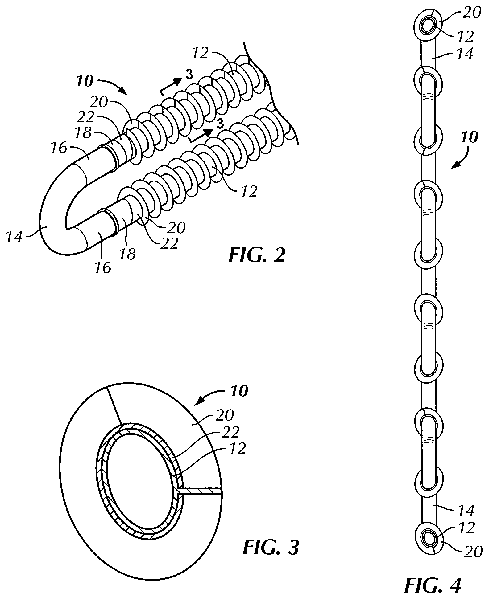
[0031] FIG. 2 is an enlarged view of a portion of the serpentine tube of FIG. 1, showing the area in FIG. 1 within the circle designated "FIG. 2."
[0032] FIG. 3 is a vertical cross-section view taken along lines 3-3 of the embodiment of FIG. 2.
[0033] FIG. 4 is an end elevation view taken along the left-hand end of FIG. 1, showing a serpentine tube having a generally vertical plane extending 90.degree. into the plane of the drawing sheet.
[0034] FIG. 5A is a first embodiment view, partly in end elevation and partly in vertical cross-section, of a portion of four tubes of a plurality of serpentine tubes of a coil assembly, taken along lines 5-5 of the embodiment of FIG. 1, showing the generally elliptical segments having their major axes generally vertically aligned and generally parallel to the plane of the return bends when the tubes are generally vertically oriented as shown with respect to the tube in FIG. 4.
[0035] FIG. 5B is a second embodiment view, partly in end elevation and partly in vertical cross-section, of a portion of four tubes of a plurality of serpentine tubes of a coil assembly, taken along lines 5-5 of the embodiment of FIG. 1, showing generally elliptical segments having their major axes of adjacent tubes on different levels angled in opposite directions with respect to each other and to the plane of the return bends as shown in FIG. 4.
[0036] FIG. 6 is an isometric view of one embodiment of an exemplary coil assembly made using the finned tubes of the present invention.
[0037] FIG. 6A is a schematic side elevation drawing of the embodiment of the exemplary coil assembly of FIG. 6 made using serpentine finned tubes of the present invention.
[0038] FIG. 6B is a schematic side elevation drawing of an alternative embodiment of an exemplary coil assembly made using the finned tubes of the present invention.
[0039] FIG. 6C is a schematic side elevation drawing of another alternative embodiment of an exemplary coil assembly made using the finned tubes of the present invention.
[0040] FIG. 7 is a schematic, vertical cross-section view of a first embodiment of an induced draft, counterflow, evaporative heat exchanger including an arrangement of two finned tube coil assemblies of the present invention within the evaporative heat exchanger.
[0041] FIG. 8 is a schematic, vertical cross-section view of an embodiment of a forced draft, counterflow, evaporative heat exchanger including an arrangement of two finned tube coil assemblies of the present invention within the evaporative heat exchanger, with some typical components removed for the sake of clarity.
[0042] FIG. 9 is a schematic, vertical cross-section view of an embodiment of an induced draft evaporative heat exchanger including an arrangement of a finned tube coil assembly of the present invention located directly below a direct contact heat transfer media section including wet deck fill within the evaporative heat exchanger, with some typical components removed for the sake of clarity.
[0043] FIG. 10 is a schematic, vertical cross-section view of another embodiment of an induced draft evaporative heat exchanger including an arrangement of a finned tube coil assembly of the present invention located directly above a direct contact heat transfer media section including wet deck fill within the evaporative heat exchanger, with some typical components removed for the sake of clarity.
[0044] FIG. 11 is a schematic, vertical cross-section view of an embodiment of an induced draft, counterflow evaporative heat exchanger including an arrangement of a finned tube coil assembly of the present invention located in a spaced configuration below fill within the evaporative heat exchanger, with some typical components removed for the sake of clarity.
[0045] FIG. 12 is a graph of results of testing of various embodiments of an evaporative heat exchanger using coil assemblies of the present invention as compared to other types of coil assemblies under equivalent conditions using test procedures as explained hereinafter.
DETAILED DESCRIPTION OF THE PREFERRED EMBODIMENTS
[0046] The present invention will be described with reference to the drawings, where like numerals indicate like elements throughout the several views, and initially with reference to FIGS. 1-4, 5A and 5B showing embodiments of a finned tube, together with FIGS. 6, 6A, 6B and 6C, showing various embodiments of a coil assembly made using a number of the finned tubes, as well as FIG. 7, showing one embodiment of an exemplary evaporative heat exchange apparatus containing the coil assembly of the finned tubes of the present invention.
[0047] While the preferred embodiments of the invention use finned tubes of the present invention for all of the tubes in a coil assembly of an evaporative heat exchange apparatus to provide the greatest advantages and benefits of the invention, and are the embodiments described in detail hereinafter, other embodiments of the invention include using at least one finned tube of the present invention in a coil assembly together with other, non-finned tubes in such a coil assembly. Preferably a plurality of finned tubes, such that at least some, more preferably the majority, and most preferably as mentioned above, all of the tubes in a coil assembly for an evaporative heat exchange apparatus are the finned tubes of the present invention. When finned tubes are used in such a coil assembly together with non-finned tubes, the finned tubes are used in any desired arrangement of finned and non-finned tubes, but preferably and without limitation, the finned tubes may usually be arranged to be on the top portion of a coil assembly and the non-finned tubes may be on the bottom portion of the coil assembly.
[0048] The basic component of the present invention is a finned tube 10, preferably but not exclusively in the form of a serpentine tube best seen in FIGS. 1-4, formed to provide the advantages of the invention when combined with other such finned tubes into a coil assembly 24 (see FIGS. 6 and 6A). The coil assembly 24 has a major plane 25, that in turn is used in an evaporative heat exchange apparatus, such as evaporative heat exchanger 26, for example (see FIG. 7). When the finned tube 10 is in the preferred form of a serpentine tube, it has a plurality of generally straight segments 12 that have a longitudinal axis 13 and which are interconnected by return bends 16. The tubes 10 may be made of any heat-conductive metal, such as galvanized steel, stainless steel, copper, aluminum or the like. Stainless steel and galvanized steel, where the zinc is applied to the steel to form galvanized steel after tubes are assembled into a coil assembly 24, are the presently preferred materials for the tubes 10 for most evaporative heat exchange applications.
[0049] The return bends 16 may be integrally and unitarily formed with the segments 12 to form the tubes 10. Alternatively, the fins can be included on the segments 12 and the return bends 14, having connector end portions 16 can be connected to connector end portions 18 of the segment 12 after fins 20 are formed on the outer surface of the segments 12. The connecting end portions 16 of the return bend 14 match the shape and are typically slightly larger in cross-sectional area than the connecting end portions 18 of the segments 12, such that the connecting end portions 18 of the segments fit within the connecting end portions 16 of the return bend 14, and may be conveniently substantially sealed in a substantially liquid-tight and preferably substantially gas-tight manner, such as by welding the connecting end portions 16 and 18 together. Alternatively, the connecting end portions 16 of the return bends 14 match the shape and may be slightly smaller in cross-sectional area than the connecting end portions 18 of the segments 12, such that the connecting end portions 18 of the segments fit over the connecting end portions 16 of the return bend 14, and may be conveniently substantially sealed in a substantially liquid-tight and preferably substantially gas-tight manner, such as by welding the connecting end portions 16 and 18 together. The connecting end portions 16 and 18 may have a generally elliptical or other cross-sectional shape. Preferably, for ease of manufacture and handling, the connecting end portions 16 and 18 have a generally circular cross-sectional shape, such that it is easier to orient and connect together the connecting end portions 16 and 18, and so that uniform return bends 14 can be used that preferably have a generally circular cross-sectional shape throughout their curved length from one connecting end portion 16 to the opposite connecting end portion 16. However, if desired, such as for creating a more tightly packed coil assembly of a plurality of generally horizontally arranged tubes 10, the return bends may have a generally elliptical cross-sectional shape, where major axes of the ellipses of the body of the return bends 14 between the connector end portions 16 are oriented in a generally vertical direction, for most applications within an evaporative heat exchanger. Alternatively, the return bends 14 may have a kidney-shaped cross-section throughout their length, with or without kidney-shaped connecting end portions 16 if the connecting end portions 18 of the segments 12 have matching kidney-shaped cross-sections. It is preferred to connect the return bends 14 to the segments 12 after the fins 20 have been applied to the segments, for ease of manufacture.
[0050] The tubes 10 are assembled into a coil assembly 24, best seen in FIGS. 6 and 6A, where the tubes 10 are serpentine tubes. Typically, a coil assembly 24 has a generally rectangular overall shape retained in a frame 28, and is made of multiple serpentine tubes 10, where the segments 12 are generally horizontal and closely spaced and arranged in levels in planes generally parallel to the major plane 25 of the coil assembly 24. The coil assembly 24 has an inlet 30 connected to an inlet manifold or header 32, which fluidly connects to inlet ends of the serpentine tubes 10 of the coil assembly, and an outlet 34 connected to an outlet manifold or header 36, which fluidly connects to the outlet ends of the serpentine tubes 10 of the coil assembly. Although the inlet 30 is shown at the top and the outlet 34 is shown at the bottom of the coil assembly 24, the orientation of the inlet and outlet could be reversed, such that the inlet is at the bottom and the outlet is at the top, if desired. The assembled coil assembly 24 may be moved and transported as a unitary structure such that it may be dipped, if desired, if its components are made of steel, in a zinc bath to galvanize the entire coil assembly.
[0051] FIG. 6B is a schematic side elevation drawing of another alternative embodiment of an exemplary coil assembly 24 made using the finned tubes 10 of the present invention, where the finned tubes 10 are generally straight tubes that extend across the major plane 25 (not shown). In this embodiment, an inlet 30 for the internal heat transfer or process fluid is connected to an inlet manifold or header 32. The internal fluid flows from the inlet manifold or header 32 into a plurality of finned tubes 10 that are fluidly connected at one end to the inlet manifold or header 32 at an upper level and into a second, upper manifold or header 33A to which the opposite ends of the upper level finned tubes 10 are fluidly connected. The internal fluid then flows from the second, upper manifold or header 33A through a lower level of finned tubes 10 fluidly connected at one end to the second, upper manifold or header 33A into a third, intermediate manifold or header 33B to which the opposite ends of the finned tubes 10 are fluidly connected. From the third, intermediate manifold or header 33B, the internal fluid flows into a still lower level of finned tubes 10 which are fluidly connected at one end to the third, intermediate manifold or header 33B to a fourth, lower manifold or header 33C to which the opposite ends of the finned tubes 10 are fluidly connected. Then the internal fluid flows from the fourth, lower manifold or header 33C to which the one end of the lowest level of the finned tubes 10 are fluidly connected to an outlet manifold or header 36 to which the opposite ends of the finned tubes 10 are fluidly connected. An outlet 34 for the internal heat transfer or process fluid is connected to the outlet manifold or header 36. As described above regarding the embodiment of FIGS. 6 and 6A, if desired for particular uses, the flow of the internal fluid can be reversed, such that the described inlet 30 would be an outlet and the described outlet 34 would be the inlet.
[0052] FIG. 6C is a schematic side elevation drawing of an alternative embodiment of an exemplary coil assembly 24 made using the finned tubes 10 of the present invention, where the finned tubes 10 are generally straight tubes that extend across the major plane 25 (not shown) and fluidly connect directly at respective opposite ends to an inlet manifold or header 32 and to an outlet manifold or header 36. An inlet 30 for the internal heat transfer or process fluid is connected to the inlet manifold or header 32. An outlet 34 for the internal heat transfer or process fluid is connected to the outlet manifold or header 36. As described above regarding the embodiment of FIGS. 6, 6A and 6B, if desired for particular uses, the flow of the internal fluid can be reversed, such that the described inlet 30 would be an outlet and the described outlet 34 would be the inlet.
[0053] The segments 12 of the finned tubes 10 shown in FIGS. 6 and 6A and the generally straight finned tubes 10 as shown in FIGS. 6B and 6C have external fins 20, which are preferably spiral fins, that contact the outer surface of the segments 12. The fins may be serrated, may have undulations or corrugations or may be of any other desired well-known structure. If desired, collars 22 may be integrally and unitarily formed with the fins 20, where the collars 22 provide a direct and secure contact with the surface of the tubes 10 or segments 12 over a greater surface area than if only the edges of the fins 20 were in contact with the outer surface of the tubes 10 or segments 12. The fins 20 and collars 22 may be formed simultaneously on the tubes 10 or segments 12 using commercially available equipment in a manner known to those involved with producing filmed tubes, and especially spiral finned tubes. Alternatively, the fins 20, with or without collars 20 may be applied individually onto the outer surface of the tubes 10 or segments 12, and then secured, such as by welding, into place, but this is an expensive and labor intensive manner of applying the fins 20 to the tubes 10 or segments 12.
[0054] Preferably, the fins 20 are applied spirally in a continuous manner to the tubes 10 or segments 12 by conventional equipment. The fins 20 are formed from a band of metal of the same type as used in for the tubes 10, and the band is fed from a source of the band at a rate and in a manner to spirally wrapped around the tube 10 or segment 12 as the tube 10 or segment 12 is advanced longitudinally along and rotated around its longitudinal axis 13 through the spiral fin forming equipment. As the fins 20 are wrapped around the tube 10 or segment 12, the inner radius of the fins 20 buckles while the outer radius does not, which creates minor corrugations or indentations in the fins themselves. This buckling occurs in a regular, repeating process in a left-to-right pattern to form undulations in and out of the plane of the material used to form the fins, not shown in FIGS. 2 and 3.
[0055] If collars 22 are desired, the band of metal of the same type as used in for the tubes 10, is fed from a source of the band at a rate and in a manner to be bent longitudinally to provide a flat portion that becomes the collars 22 and an upstanding portion that becomes the fins 20. The bent metal band is spirally wrapped around the segments 12 as the segments 12 are advanced longitudinally along and rotated around their longitudinal axis 13 through the spiral fin forming equipment. When the strip of metal is spirally applied to the segments to form the fins 20 with collars 22, the fins 20 typically have undulations in and out of their plane, rather than straight as shown in FIGS. 2 and 3 for the ease of illustration, while the collars 22 are flat against the surface of the segments 12, resulting from the metal deformation during the application of the strip of metal to the advancing and rotating segments.
[0056] FIGS. 5A and 5B show respective first and second embodiments, partly in end elevation and partly in vertical cross-section, of a portion of four serpentine tubes 10A or 10B, for FIGS. 5A and 5B, respectively, of a plurality of tubes 10 of a coil assembly 24, taken along lines 5-5 of the embodiment of FIG. 1. As shown, starting from the left-hand side of each of FIGS. 5A and 5B, the second and fourth tubes are shown in a preferred orientation as being staggered in height, or vertically (as shown, lower), with respect to their next generally horizontally adjacent first and third tubes. FIGS. 5A and 5B also illustrate alternative embodiments of orientations of the major axes of the generally elliptical segments 12A of serpentine tubes 10A in FIG. 5A and the generally elliptical segments 12B of serpentine tubes 10B in FIG. 5B. Otherwise, the embodiments of FIGS. 5A and 5B are similar to each other. In FIGS. 5A and 5B, the cross-section of FIG. 1 was selected such that the fins are not shown or described for the sake of clarity, but the orientations of the major and minor axes of the generally elliptical segments should be understood as relating to the entire length of the finned segments 12 until they connect with or are unitarily formed with the return bends 14A and 14B. Although each of the return bends 14A and 14B is shown as having a circular cross-sectional shape, as explained above, the return bends 14A and 14B may alternatively have a generally elliptical cross-sectional shape, a generally kidney-shaped cross-sectional shape, or other cross-sectional shape. For ease of explanation, the orientation of the major axes of the generally elliptical finned segments 12A and 12B will be described in the preferred embodiment of the serpentine tubes 10 as shown in the embodiment illustrated in FIGS. 6 and 6A, but in principle, the same orientation can be and, preferably, is provided for the generally straight and generally elliptical finned tubes 10 used in a coil assembly such as the coil assemblies shown in FIGS. 6B and 6C.
[0057] In both FIGS. 5A and 5B, the segments 12A or 12B of adjacent tubes are generally vertically spaced from each other within planes generally parallel to the major plane 25 of the coil assembly 24 at respective upper generally horizontal levels L1A and L1B and respective lower generally horizontal levels L2A and L2B. Thus, the segments 12A or 12B of adjacent tubes 10A or 10B are in planes generally parallel to the major plane 25 and are staggered and spaced with respect to each other generally vertically to form a plurality of staggered generally horizontal levels in which every other segment is aligned in the same generally horizontal level generally parallel to the major plane 25.
[0058] In the first embodiment of FIG. 5A, the generally elliptical segments 12A have their major axes generally vertically aligned and generally parallel to the plane of the return bends 14A when the tubes 10A are generally vertically oriented as shown with respect to the tube 10 in FIG. 4. This alignment or orientation is regardless of whether the segments are on an upper generally horizontal vertical level L1A or a lower horizontal level, such as the next adjacent generally horizontal level L2A.
[0059] In the second embodiment of FIG. 5B, the generally elliptical segments 12B have their major axes of the tubes 10B on the different, next adjacent generally horizontal levels L1B and L2B, angled in opposite directions with respect to the plane of the return bends 14B when the tubes 10B are generally vertically oriented as shown with respect to the tube 10 in FIG. 4. As shown in FIG. 5B, in a preferred embodiment where the major axes of the segments 12 are oriented in opposite directions on adjacent horizontal levels, the angle of all of the major axes on a first generally horizontal level L1B is about 20.degree. from the plane of the return bends and the angle of all of the major axes on the next adjacent generally horizontal level L2B is about 340.degree. from the plane of the return bends. In this configuration, each horizontal level L1B, the major axes of all of the segments 12B are oriented in the same angled direction and on the next adjacent lower level L2B, the major axes of all the segments are oriented in the same angled direction, but in an opposite angled orientation from the angled orientation of the major axes in level L1B. Where the major axes are angled in opposite directions on adjacent horizontal levels, they are sometimes known as a "ric-rac" arrangement or orientation, and this term is used in the Table below to designate this type of arrangement or orientation. If desired, however, on each level L1B or L2B, the major axes of the segments within the same generally horizontal level may be angled in opposite directions.
[0060] Thus, as represented in FIGS. 5A and 5B, the major axes of the finned segments 12A or 12B on a first generally horizontal level L1A or L1B, respectively, may be 0.degree. to about 25.degree. degrees from the plane of the return bends and the angle of the major axes of the finned segments 12B or 12A, respectively, on the next adjacent generally horizontal level L2B or L2A, respectively, may be about 335.degree. to 360.degree. from the plane of the return bends. FIG. 4 shows the oppositely angled major axes of the finned segments 12 as described with respect to FIG. 5B for a complete serpentine tube 10.
[0061] The return bends 14, 14A and 14B are shown as being generally circular in cross-section. The outside diameter of the circular cross-section of the return bends substantially equals the nominal tube outside diameter that is an average of the lengths of the major and minor axes of the segments 12, 12A and 12B having a generally elliptical cross-section. Preferably, but without limitation, the outside diameter of the return bends and the nominal tube outside diameter are about and preferably substantially 1.05 inches (2.67 cm), where the wall thickness of the tubes forming the segments 12 and the return bends 14 is about 0.055 inch (0.14 cm). The minor axis of the generally elliptical tube 10 or segments 12, 12A and 12B is about 0.5 to about 0.9 times, and preferably about 0.8 times the nominal tube outside diameter. Thus, the generally elliptical straight tubes 10 and segments 12, 12A and 12B having a nominal tube outside diameter of 1.05 inches (2.67 cm), would have a minor axis length of about and preferably substantially 0.525 inch (1.334 cm) to about and preferably substantially 0.945 inch (2.4 cm), and preferably about and preferably substantially 0.84 inch (2.134 cm). Tubes 10 with these dimensions have been found to have a good balance among an appropriate inner diameter or dimensions to allow the processing fluid in the form of any desired gas or liquid to easily flow within the tubes 10, proximity of such processing fluid to the tube wall for good heat transfer through the walls of the tubes with the elliptical cross-sectional shape that has a large effective surface area, and ability to provide an appropriate number of tubes 10 to be packed into a coil assembly 24. The tubes are strong, durable and when in serpentine form, able to be readily worked, including connecting the segments 12 and return bends 14 and placement within a coil assembly 24. Depending on the environment and intended use of the evaporative heat exchangers, such as the evaporative heat exchanger 26, in which the finned tubes 10 of the present invention are placed, the dimensions and cross-sectional shape of the tubes 10 may be varied considerably.
[0062] The spacing and orientation of the tubes 10 having the generally elliptical cross-sectional shape or segments having the generally elliptical cross-sectional shape within a coil assembly 24 are important factors for the performance of the evaporative heat exchanger containing the coil assembly 24. If the spacing between segments 12 is too tight, air and water flow through and turbulent mixing within the coil assembly will be adversely affected and fans with greater horsepower will be needed and there will be an increased pressure drop. If the spacing between segments 12 is too great, then there will be less tubes per surface area of the major plane 25 of the coil assembly 24, reducing the heat transfer capacity, and there may be inadequate, as in insufficient for example, mixing of the air and water, adversely affecting the degree of evaporation, and thereby heat exchange. The orientation of the segments 12, particularly with respect to the angle of the major axes of the segments, also affects the heat exchange ability of an evaporative heat exchanger with which they are used.
[0063] The spacing of the fins 20 around the outer surface of the segments 12 is critical. If the fin spacing is too close (too many fins per inch, for example), the ability of the external heat exchange liquid and the air to effectively mix turbulently is adversely affected and the fins 20 may block the space externally of the coil assembly 24, such that greater air mover power is needed. Similar concerns involve the critical determination of the height of the fins (the distance from the proximal point where the base of the fins 20 contact the outer surface of the segments 12 and the distal tip of the fins). While higher fins have greater surface area which the evaporating water may coat, longer fins may block the air passage. Thicker fins 20 also have similar critical concerns. Thicker fins are more durable and are better able to withstand the forces of water and air, as well as other material that may be entrained in either as they pass through a coil assembly, but thicker fins may also block the flow of water or air through the coil assembly and would be more expensive to manufacture. All of these factors adversely affect performance.
[0064] If the fin spacing is too great (not enough fins per inch, for example), the advantages of a sufficient number of fins 20 for the evaporative water to coat would not be present and there may be an adverse effect on the desired mixing of the water and air responsible for efficient evaporation. Similar concerns are present when the fin height is too low, as there is not enough structure of the fins to be coated with the water, and there may be less mixing of the water and air. Thinner fins may not be sufficiently durable to withstand the hostile environment to which they are subject in evaporative heat exchangers and if the fins are too thin, they could be bent during operation as they are subject to the forces of both the water and air impacting them, adversely affecting flow of both the water and air. In addition, and more significantly, thinner fins transfer less heat.
[0065] The present invention was conceived and developed in view of the foregoing factors of tube shape, orientation, arrangement and spacing, and fin spacing, height and thickness, all of which must be carefully balanced, and which was a difficult task requiring considerable testing and experimentation. Based on such work, the appropriate parameters of tube shape, arrangement, orientation and spacing, as well as fin spacing, height and thickness were determined.
[0066] The orientation and spacing, within a coil assembly 24 and an evaporative heat exchanger, of the tubes 10 with their segments 12 and return bends 14 will be described primarily with reference to FIGS. 5A and 5B. The center-to-center spacing D.sub.H generally horizontally (which will be generally parallel to the major plane 25 in FIG. 6) and generally normal to the longitudinal axis 13 of the segments 12, 12A and 12B is substantially 100% to substantially 131%, preferably substantially 106% to substantially 118%, and more preferably substantially 112% of the nominal tube outside diameter. The vertical straight tube or segment spacing D.sub.V generally is not as critical to the performance of an evaporative heat exchanger as the horizontal tube or segment spacing D.sub.H. The segments 12, 12A and 12B have a generally vertical center-to-center spacing of substantially 110% to substantially 300% of the nominal tube outside diameter, preferably substantially 150% to substantially 205% of the nominal tube outside diameter, and more preferably, substantially 179% of the nominal tube outside diameter. This generally vertical center-to center spacing is indicated by the distance D.sub.V between the upper generally horizontal levels L1A and L1B and the lower generally horizontal levels L2A and L2B, respectively.
[0067] These parameters may be applied as follows to the presently preferred embodiment, where the nominal tube outside diameter is substantially 1.05 inches (2.67 cm). The center-to-center spacing D.sub.H of the finned straight tubes 10 or segments 12, 12A and 12B of the serpentine finned tubes 10 would be substantially 1.05 inches (2.67 cm) to substantially 1.38 inches (3.51 cm), preferably substantially 1.11 inches (2.82 cm) to substantially 1.24 inches (3.15 cm), and more preferably substantially 1.175 inches (2.985 cm). The finned tubes 10 or the finned segments 12, 12A and 12B would have a generally vertical center-to-center spacing D.sub.V of substantially 1.15 inches (2.92 cm) to substantially 3.15 inches (8.00 cm), preferably substantially 1.57 inches (3.99 cm) to substantially 2.15 inches (5.46 cm), and more preferably substantially 1.88 inches (4.78 cm). In some embodiments, the major axes of the finned tubes 10 or the finned segments 12, 12A are oriented substantially vertically, so that they are generally parallel to the plane of the return bends 14 as shown in FIG. 4. In other embodiments, the major axes of the finned tubes 10 or the finned segments 12B may be greater than 0.degree. to about 25.degree., and preferably about 20.degree., from the plane of the return bends 14 and the angle of the major axes of the finned tubes 10 or the finned segments 12B on the next vertically adjacent generally horizontal level, may be about 335.degree. to less than 360.degree., and preferably about 340.degree. from the plane of the return bends 14, such that the major axes of the finned tubes 10 or the finned segments 12 are oriented in opposite directions on vertically adjacent horizontal levels.
[0068] The parameters relating to the fins 20, namely fin spacing along the longitudinal axis 13 of the segments 12, the fin height from the outer surface of the segments 12 and the fin thickness are as follows according to the present invention.
[0069] The fins 20 are preferably spiral fins and have a spacing of substantially 1.5 to substantially 3.5 fins per inch (2.54 cm) along the longitudinal axis 13 of the segments 12, preferably substantially 2.75 to substantially 3.25 fins per inch (2.54 cm) and more preferably substantially 3 fins per inch (2.54 cm). Expressed alternatively, the center-to-center distance between the fins is therefore, respectively, substantially 0.667 inch (1.694 cm) to substantially 0.286 inch (0.726 cm), preferably substantially 0.364 inch (0.925 cm) to substantially 0.308 inch (0.782 cm), and more preferably substantially 0.333 inch (0.846 cm).
[0070] The fins 20 have a height of substantially 23.8% to substantially 36% of the nominal tube outside diameter, preferably substantially 28% to substantially 33% of the nominal tube outside diameter, and more preferably substantially 29.76% of the nominal tube outside diameter. These parameters may be applied as follows to the presently preferred embodiment, where the nominal tube outside diameter is substantially 1.05 inches (2.667 cm). In this embodiment, the fins 20 have a height of substantially 0.25 inch (0.635 cm) to substantially 0.375 inch (0.953 cm), preferably substantially 0.294 inch (0.747 cm) to substantially 0.347 inch (0.881 cm), and more preferably 0.3125 inch (0.794 cm).
[0071] The fins 20 have a thickness of substantially 0.007 inch (0.018 cm) to substantially 0.020 inch (0.051 cm), preferably substantially 0.009 inch (0.023 cm) to substantially 0.015 inch (0.038 cm), and more preferably substantially 0.01 inch (0.025 cm) to substantially 0.013 inch (0.033 cm). As noted above in the "Definitions" section, dimensions for the thickness of the fins are for the fins on the finned tubes prior to any later treatment of the finned tubes themselves or of any coil assembly containing them. Where the finned tubes or coil assembly are subjected to a later treatment, typically by galvanizing steel finned tubes or more typically, galvanizing the entire coil assembly containing them, the thickness of the fins increases by the thickness of the zinc coating applied during galvanization. Also typically, the fins after galvanization are thicker at a base proximal to the outer surface of the tube than at a tip of the fins distal from the outer surface of the tube. Because the fins are thicker after galvanizing, the spacing between the fins is reduced accordingly. Usually this is not of concern concerning the thermal performance or heat capacity of the evaporative heat exchangers and the rust or other corrosion inhibition of the galvanizing is important in providing the finned tubes and coil assemblies with greater longevity than if they were not galvanized.
[0072] The coil assembly 24 of any desired configuration, such as shown in any of FIG. 6, 6A, 6B or 6C, is then installed into an evaporative heat exchanger apparatus, such as evaporative heat exchanger 26, as shown in FIG. 7. Evaporative heat exchangers have many varied configurations, and several are shown schematically in FIGS. 7-11. Typical evaporative heat exchangers in which the coil assembly 24 of the present invention may be used are, for example without limitation, any of several available from Evapco, Inc., such as Models ATWB or ATC, which may include the components and operate as disclosed in Evapco, Inc.'s U.S. Pat. No. 4,755,331. Evaporative heat exchange apparatus, though they many variations, have the basic structure and operation described below, initially with reference to FIG. 7.
[0073] FIG. 7 is a schematic, vertical cross-section view of an embodiment of an induced draft, counterflow, evaporative heat exchanger 26, where water flows generally vertically downwardly and air flows generally vertically upwardly through the plenum and coil assembly, including an arrangement of two finned tube coil assemblies 24 of the present invention within the evaporative heat exchanger. The evaporative heat exchanger 26 has a housing 38 enclosing a plenum 40 having a generally vertical longitudinal axis 42. One or more coil assemblies 24 are mounted within the plenum 40 such that the major plane 25 of each coil assembly is generally normal to the longitudinal axis 42 of the plenum. In this way, the generally vertical plane of the return bends 14 in the preferred embodiment using serpentine tubes 10, as shown in FIG. 4 and as indicated by the generally vertical alignment of the tubes 10 in the coil assemblies as shown in FIG. 7, are also generally normal to the major plane 25 of the coil assemblies 24 and parallel to the longitudinal axis 42 of the plenum. Based on this alignment, the finned segments 12, with their longitudinal axes 13, of the tubes 10 are also in generally horizontal staggered planes parallel to the major plane 25 of the coil assemblies 24 and generally normal to the longitudinal axis 42 of the plenum 40. If generally straight finned tubes 10 are used as shown in FIGS. 6B and 6C, then the finned tubes with their longitudinal axes also are in generally horizontal staggered planes parallel to the major plane 25 of the coil assemblies 24 and generally normal to the longitudinal axis 42 of the plenum 40.
[0074] Air flows from the ambient atmosphere around the heat exchanger 26 via air inlets 44 which may, and preferably do, have louvers, or more preferably, selectively openable and closeable air inlet dampers 45 that may be closed or partially or fully opened based on various atmospheric and operating conditions, in a well-known manner, and to protect the plenum 40 from inclusion of unwanted objects. In the embodiment of FIG. 7, air is drawn into the plenum 40, passes though the coil assemblies 24 and exits an air outlet 46 by the action of an air mover located in an air outlet housing 50. The air mover in this embodiment is shown as a fan 48, in the form of a propeller fan, which is preferred for use as an induced draft fan to draw air from the ambient atmosphere. Other types of fans, such as centrifugal fans, could be, but usually are not used as induced draft fans. A grating or screen (not shown) is placed over the fan 48 for safety and to keep debris away from the fan 48 and out of the evaporative heat exchanger 26.
[0075] A bottom wall of the evaporative heat exchanger 26, together with the adjoining front, back and side walls, defines a sump 52 for the water or other external heat exchange liquid. If desired, a drain pipe with an appropriate valve and a fill pipe with an appropriate valve (none of which is shown) may be included for draining and filling or replenishing the sump 52. Water in the sump 52 is circulated to a liquid distributor assembly 54, which when turned on distributes, via spray nozzles, orifices in a pipe or via other known devices and techniques, the water as the evaporative heat transfer liquid above the coil assemblies 24. The distributor assembly 54 is connected to one end of a conduit 56 in fluid connection at the other end to the water in the sump. The distributor assembly 54 is activated or turned on typically when a pump 58 is turned on to pump water from the sump 52 to the distributor assembly 54 through the conduit 56.
[0076] The evaporative heat exchanger 26 also preferably includes drift eliminators 60 above the liquid distributor assembly 54 and below the fan 48 and air outlet 46. The drift eliminators very significantly reduce water droplets or mist entrained in the air exiting the outlet 46. Many drift eliminators of various materials are available commercially. The presently preferred drift eliminators are PVC drift eliminators available from Evapco, Inc. as disclosed in Evapco, Inc.'s U.S. Pat. No. 6,315,804, the disclosure of which is hereby incorporated by reference herein in its entirety.
[0077] In operation, as air is drawn into the plenum 40 through the air inlets 44 and any associated louvers or dampers 45, it is also drawn through the coil assemblies 24. Water is distributed over the coil assemblies 24 by the liquid distributor 54. As the air travels upwardly through the coil assemblies 24 it is mixed with the water, with an appropriate degree of turbulence as provided by the orientation and arrangement of the finned segments 12 having the fins 20 with the characteristics, dimensions and parameters disclosed above. The water coats the outer surfaces of the tubes 10, including the segments 12 having the generally elliptical cross-sectional shape, as well as the fins 20. The air causes the water to evaporate, thereby cooling the water, such that the cooled water exchanges heat with the tubes 10 of the coil assembly and the process fluid contained internally within the tubes 10. Water ultimately passes through the coil assemblies 24 and is collected in the sump 52, and recycled into the liquid distributor 54 through the conduit 56 by the pump. The air with any entrained water is drawn upwardly through the drift eliminators 60, whereby most, and preferably almost all, of the water is removed from the air stream, before the air is exhausted through the air outlet 46 by the fan 48.
[0078] As noted above, the coil assemblies 24 having the finned tubes 10 of the present invention may be used in a large variety and types of evaporative heat exchange apparatus. FIGS. 8-11 schematically illustrate a small sample of such various evaporative heat exchangers, with some typical components shown in FIG. 7 removed for the sake of clarity. In FIGS. 8-11, components that are shown and that are the same as those in FIG. 7 are not described again, but are identified by like numerals used in FIG. 7, except that a letter designation common to the embodiments of each of FIGS. 8-11 is used, where, for example, the coil assemblies 24A are used in the evaporative heat exchanger 26A of FIG. 8, the coil assembly 24B is used in the evaporative heat exchanger 26B of FIG. 9, the coil assembly 24C is used in the evaporative heat exchanger 26C of FIG. 10 and the coil assembly 24D is used in the evaporative heat exchanger 26D of FIG. 11. Any new components not used in a previous Fig. are identified by a different numeral.
[0079] FIG. 8 is a schematic, vertical cross-section view of an embodiment of a forced draft, counterflow, evaporative heat exchanger 26A including an arrangement of two finned tube coil assemblies 24A of the present invention within the plenum 40A of the evaporative heat exchanger. Here, compared to the induced draft evaporative heat exchanger 26 of FIG. 7, instead of using a propeller fan 48 mounted in an air outlet housing 50, the forced draft evaporative heat exchanger 26A of FIG. 8 uses a centrifugal fan 62 type of air mover to force air, entering the plenum 40A within the housing 38A through a screen 47 covering the air inlet. The air is then forced generally vertically upwardly and through the coil assemblies 24A, through which water is flowing generally vertically downwardly. Thereafter, the air moves through the drift eliminators 60A and out of the evaporative heat exchanger 26A through the air outlet 46A. The centrifugal fan 62 is typically mounted within a lower portion at one side of the housing 38A adjacent an air inlet typically covered by a screen 47. The sump for the water is not shown in FIG. 8, but would be present below the coil assemblies 24A such that the water in the sump is blocked from reaching the centrifugal fan 62.
[0080] FIG. 9 is a schematic, vertical cross-section view of an embodiment of an induced draft evaporative heat exchanger 26B including an arrangement of a finned tube coil assembly 24B of the present invention located directly below a direct contact heat transfer media section including wet deck fill 64, described below, within the plenum 40B of the evaporative heat exchanger. In the evaporative heat exchanger 26B of FIG. 9, air is drawn into the plenum 40B through an air inlet 44B and any associated louvers or dampers 45B, where the air inlet 44B is laterally adjacent to the coil assembly 24B. The evaporative heat exchanger 26B of FIG. 9 differs in a first respect from the evaporative heat exchanger 26 of FIG. 7, in that the air is drawn through the coil assembly 24B in a direction generally normal, transverse or horizontally with respect to the generally vertical downwardly flow of water externally through the coil assembly 24B, known in the industry as a crossflow arrangement. The mixing and turbulence of the air and water externally through the coil assembly 24B in a crossflow arrangement is somewhat different than but still quite effective, compared to the mixing and turbulence of the air and water externally through the coil assembly 24 of FIG. 7 in a counterflow arrangement.
[0081] The evaporative heat exchanger 26B of FIG. 9 differs in a second respect from the evaporative heat exchanger 26 of FIG. 7 in that the evaporative heat exchanger 26B of FIG. 9 includes a direct contact heat exchange section containing wet deck fill 64 below the liquid distributor 54B and above the coil assembly 24B, which provides direct, evaporative heat exchange when the air flow and the evaporative water or other cooling liquid come into direct contact with each other and are mixed with some desired degree of turbulence within the wet deck fill 64 resulting in additional evaporative cooling. The turbulent mixing of the air and water in the wet deck fill 64 allows for greater heat transfer between the air and water, but the benefits of the increased turbulent mixing in the wet deck fill 64 should not be overcome by potential adverse effects on the energy requirements of a larger fan motor or fan size or air flow reduction. As noted above, there is a fine balance among these factors when deciding whether and what type of wet deck fill heat transfer media to use. That is why the use of the wet deck fill 64 is optional in evaporative heat exchangers using the coil assembly of the present invention. The wet deck fill may be any standard fill media, such as plastic fill, typically PVC, as well as wood or ceramic fill media, or any other fill media known in the art. The presently preferred fill media is Evapco, Inc.'s EVAPAK.RTM. PVC fill, disclosed in Evapco, Inc.'s U.S. Pat. No. 5,124,087, the disclosure of which is hereby incorporated by reference herein, in its entirety. When wet deck fill 64 is used, it may be located above the coil assembly 24B as shown in FIG. 9, or below the coil assembly 24C as shown in FIG. 10, since in either location, the additional heat transfer in the wet deck fill 64 will further evaporatively cool the water draining into the sump 52B or 52C.
[0082] In the embodiment of FIG. 9, louvers 65 are built into the inlet side of the wet deck fill 64, such that the air may be drawn through the louvers 65 into the wet deck fill in a crossflow manner as described above with respect to the crossflow arrangement concerning the coil assembly 24B.
[0083] The embodiment of the evaporative heat exchanger 26B of FIG. 9 operates as follows. Ambient air in the environment of the evaporative heat exchanger is drawn into the plenum 40B through the air inlets 44B and any associated louvers or dampers 45B, and in a crossflow manner externally through the coil assembly 24B, though which water, pre-cooled in the wet deck fill 64 of the direct contact heat exchange section, externally flows generally vertically downwardly. Ambient air is also drawn into the wet deck fill 64 in a crossflow manner with respect to the water flowing generally vertically downwardly through the louvers 65, where the water is evaporatively cooled before it contacts the coil assembly 24B below the wet deck fill 64. The air is then drawn from the wet deck fill 64 into the plenum 40B.
[0084] Water is distributed over the wet deck fill 64 by the liquid distributor 54B where it is initially cooled evaporatively by mixing with the air flowing through the wet deck fill 64 before draining into the coil assembly 24B where it is turbulently mixed with the air and thereafter is drained from the coil assembly 24B and collected in the sump 52B. The water is recycled from the sump 52B into the liquid distributor 54B through the conduit 56B by the pump 58B. The air, with any entrained water, in the plenum 40B is drawn upwardly through drift eliminators 60 (not shown in FIG. 9) by the fan 48B in the air outlet housing 50B, before the air is exhausted through the air outlet 46B.
[0085] FIG. 10 is a schematic, vertical cross-section view of another embodiment of an induced draft evaporative heat exchanger 26C including an arrangement of a finned tube coil assembly 24C of the present invention located directly above a direct contact heat transfer media section including wet deck fill 64C within the plenum 40C of the evaporative heat exchanger. The embodiment of the evaporative heat exchanger 26C of FIG. 10 operates as follows. One portion of ambient air in the environment of the evaporative heat exchanger is drawn into the apparatus through an inlet 44C at the top of the apparatus aligned above the coil assembly 24C and flows downwardly externally through the coil assembly in a generally vertical direction concurrent with the flow of water distributed over the coil assembly by the liquid distributor 54C. Another portion of ambient air is also drawn into apparatus through the direct contact heat exchange section containing the wet deck fill 64C through the optional louvers 65C. The air traveling through the wet deck fill 64C moves in a crossflow manner to water draining generally vertically from the coil assembly 24C.
[0086] Water is distributed over the coil assembly 24C by the liquid distributor 54C where it is mixed with the concurrently flowing air, thereby being cooled evaporatively in the coil assembly, exchanging heat with the coil assembly 24C, before draining into and through the wet deck fill 64C. In the wet deck fill 64C, the water is further turbulently mixed with the cross-flowing air where it is further evaporatively cooled, and thereafter is drained from the wet deck fill 64C and collected in the sump 52C. The water is recycled from the sump 52C into the liquid distributor 54C through the conduit 56C by the pump 58C. The air with any entrained water is drawn into the plenum 40C and then upwardly through drift eliminators 60 (not shown in FIG. 10) by the fan 48C in the air outlet housing 50C, before the air is exhausted through the air outlet 46C.
[0087] FIG. 11 is a schematic, vertical cross-section view of an embodiment of an induced draft, counterflow, evaporative heat exchanger 26D including an arrangement of a finned tube coil assembly 24D located in a spaced configuration below wet deck fill 64D within the plenum 40D in the housing 38D in the evaporative heat exchanger.
[0088] The embodiment of the evaporative heat exchanger 26D of FIG. 11 operates as follows. Air in the environment of the evaporative heat exchanger is drawn into the plenum 40D through the air inlets 44D and any associated louvers or dampers 45D, and then is drawn into the wet deck fill 64D in a counterflow manner with respect to the water flowing generally vertically downward through the wet deck fill 64D. The liquid distributor 54 (not shown in FIG. 11), located above the wet deck fill 64D and below the drift eliminators (not shown in FIG. 11), distributes the water over the wet deck fill 64D where it is turbulently mixed with the air, thereby being cooled evaporatively. Then, the cooled water drains over the coil assembly 24D, exchanging heat with the coil assembly 24D, before draining into and being collected in the sump 52D. If desired, the water draining from the wet deck fill 64D may be concentrated to flow directly over the coil assembly 24D as disclosed in Evapco, Inc.'s U.S. Pat. No. 6,598,862, the disclosure of which is hereby incorporated by reference herein, in its entirety, to more efficiently direct the cooled water to the coil assembly 24D. The water is recycled from the sump 52D into the liquid distributor 54 through the conduit 56 (not shown in FIG. 11) by the pump 58 (not shown in FIG. 11). The air with any entrained water is drawn upwardly through drift eliminators by the fan 48D in the air outlet housing 50D, before the air is exhausted through the air outlet 46D.
[0089] The performance of evaporative heat exchange apparatus is measured by the amount of heat transfer, typically but not exclusively during cooling. The measurements are affected by several factors. First, the measurements are affected by the amount and temperature of the process fluid flowing internally though the tubes 10 of the apparatus coil assembl(ies) 24 and the water or other cooling liquid flowing externally through the coil assembly. The flow rates are measured using flow meters and the temperature is measured using thermometers. The rate and temperature of the air flowing through the system is also significant, as well as the force required to drive the air mover 48 that moves the air through the apparatus. The air flow is typically measured by an anemometer in feet per minute through a tube, although other well-known air flow measuring devices could also be used, and is typically determined by the rating of the motor driving the fan of the air mover, usually expressed in horsepower (HP).
[0090] In one embodiment of the evaporative heat exchange apparatus using the coil assemblies 24 having the finned tubes 10 of the present invention, typically, but without limitation, the process fluid, in the form of water, is pumped into the inlet 30 and flows internally through the coil assembly at a rate of approximately 0.75 gpm to approximately 16.5 gpm per tube present in the coil assemblies, and preferably approximately 10 gpm per tube. The amount and rate of water that passes externally through the coil assembl(ies) 24 supplied through the water supply conduit 56 as distributed by the liquid distributor 54 is approximately 1.5 gpm/sq. ft. to approximately 7 gpm/sq. ft. of coil plan area determined with respect to the major plane 25, and is preferably approximately 3 gpm/sq. ft. to approximately 6 gpm/sq. ft. Evaporative heat exchange apparatus using the coil assemblies 24 having the finned tubes 10 of the present invention typically, but without limitation, have an air flow rate of approximately 300 feet per minute to approximately 750 feet per minute, and preferably approximately 600 feet per minute to approximately 650 feet per minute. The power of the fan motors is dependent upon the size of the evaporative heat exchanger housing, the size of the coil assemblies used, the number and configuration of tubes in the coil assemblies, the number of coil assemblies used, the presence and orientation of any optional wet deck fill, the size and type of fan used, and several other factors, so no absolute values can be presented for the power of the fan motors required. In general, and without limitation, the power of the fan motors varies within a very broad range, such as approximately 0.06 HP to approximately 0.5 HP per square foot of plan area of the coil assemblies used in the evaporative heat exchangers, corresponding to the area of the major plane 25 coextensive with the length and width of the coil assembly.
[0091] In evaporative heat exchange apparatus using the finned tube coil assemblies 24 of the present invention, performance has been shown to be enhanced by an increased air flow rate even compared to similar coil assemblies using tubes having segments 12 with a generally elliptical cross-sectional shape but not containing fins 20 as in the present invention. In view of the space occupied by the fins 20 on the segments 12 of the tubes 10 used in coil assemblies 24 of the present invention, it would have been expected that the air flow rate would have decreased, as the fins 20 would have been expected to block the flow of both air and water, so that it was unexpected and surprising when the air flow rate increased. The increase in air flow rate provided a surprising enhancement of the thermal performance in evaporative heat exchange apparatus using the coil assemblies with the finned tubes 10 of the present invention.
[0092] The enhanced thermal performance of evaporative heat exchange apparatus using the coil assemblies 24 having finned tubes of the present invention will be described in greater detail with respect to the following non-limiting test procedure whereby various coil assemblies were tested, including those of the present invention, under equivalent test conditions.
[0093] The test procedure included mounting various single coil assemblies in an Evapco, Inc. Model ATWB induced draft, counterflow, evaporative cooler in a test facility. The general arrangement of the Model ATWB induced draft, counterflow, evaporative cooler is shown in FIG. 7, except that only one coil assembly 24 was used, instead of two coil assemblies 24 as shown in FIG. 7. The tested coil assemblies all had a plan area of 6 feet (1.83 m) long (corresponding to serpentine tubes having segments with return bends fitting within frames of this length with the appropriate spacing) by 4 feet (1.22 m) wide (corresponding to 37 adjacent tubes that were packed within frames of this width with the appropriate spacing) and had ten generally horizontal rows of segments 12 with generally elliptical cross-sectional shapes connected by return bends having a circular cross-sectional shape, where the major axes of segments were arranged in various orientations. All tested coil assemblies used tubes with return bends having an outside diameter of substantially 1.05 inches (2.67 cm) and segments having a nominal tube outside diameter of substantially 1.05 inches (2.67 cm), with a substantially horizontal center-to-center spacing D.sub.H of 1.0625 inches (2.699 cm) (designated "Narrow" in the Table below) or 1.156 inches (2.936 cm) (designated "Wide" in the Table below) and a substantially vertical center-to-center spacing D.sub.V of about 1.875 inches (4.763 cm). One tested coil assembly had no fins 20 on the segments (Test ID "A" in the Table below and the graph of FIG. 12) and represented a base line against which other finned coil assemblies were compared. Other tested coil assemblies identified in the Table below and the graph of FIG. 12 had spiral fins 20 with the parameters of fin spacing and height as described and claimed herein, and some had spiral fins 20 but not having the parameters of fin spacing and height as described and claimed herein. All of the coil assemblies including fins used fins of the same thickness, namely, 0.013 inch (0.033 cm), which is within the range of fin thickness described and claimed herein. Certain other coil assemblies, namely, those having the parameters associated with the Test ID "B" and "C" (tested in a different rig) and Test ID "D" (tested using 5 HP motor) in the Table below and the graph of FIG. 12, were tested in a different manner, but the performance data presented in the graph of FIG. 12 were derived using industry calculations for standardizing performance data from apparatus of different configurations. The performance of the coil assemblies was tested over varying water flow rates internally through the coils of 60 gpm to 360 gpm, water flow rates externally through the coils of approximately 5.9 gpm per square foot, and air flow rates of 300 feet per minute (91.44 meters per minute) to 750 feet per minute (228.6 meters per minute), generated by a fan driven by a 3 HP motor (except as noted above regarding Test ID "C"). The coil assemblies tested had the parameters as set forth in the following Table:
TABLE-US-00001 Major Axes D.sub.H Tube Fin Spacing Fin Height Test ID Orientation Spacing Fins (Fins/Inch) (Inch) A 20.degree. & 340.degree. Wide No -- -- Ric-rac B 0.degree. Wide Yes 3 0.25 C 20.degree. & 340.degree. Wide Yes 1.5 0.3125 Ric-rac D 0.degree. Narrow Yes 3 0.3125 E 20.degree. & 340.degree. Wide Yes 3 0.3125 Ric-rac F 0.degree. Wide Yes 3 0.3125 G 20.degree. & 340.degree. Wide Yes 1.5 0.5 Ric-rac H 20.degree. & 340.degree. Wide Yes 3 0.5 Ric-rac
[0094] FIG. 12 is a graph of results of testing of the coil assemblies identified in the Table in the evaporative heat exchanger under the same conditions set forth in the procedure described above, with respect to preferred internal process fluid (water) flow rates from 6 to 9.8 gpm per tube (where each tube is identified as a "circuit" in the x-axis legend on the graph. The graph show curves based on the heat transferred as measured in thousands of BTU/hour (MBH) versus the water flow internally through the coil assembly in gallons/minute/tube (GPM). Each curve A to H in FIG. 12 corresponds to the respective coil assembly A to H of the above Table.
[0095] With reference to FIG. 12, the baseline performance of Curve A relates to coil assembly A, with a 20.degree. to 340.degree. ric-rac major axes segment orientation and no fins. Curves B to F above Curve A indicate that at the indicated internal water flow rate along the X-axis, such curves have a better thermal performance than the baseline performance, with increasingly better thermal performance from Curve B to Curve F.
[0096] Test ID "G" and "H" with a 20.degree.-340.degree. ric-rac major axes orientation, respective fin spacing of 1.5 and 3 fins/inch (2.54 cm) and fin height of 0.5 inch (1.27 cm) (outside the fin height parameter of the present invention) had consistently lower thermal performance (MBH) as indicated by Curves G and H, respectively.
[0097] In general, the test results show that an orientation of the major axes of the generally elliptical finned segments in a generally vertical direction (0.degree.) provides better thermal performance than a ric-rac orientation of the major axes for tubes having the same fin height and fin spacing. Nevertheless arranging the major segments in a ric-rac orientation still provides a very considerable increase in thermal performance of a coil assembly having all of the other parameters within the scope of the present invention. For tubes having the same angle of orientation, namely a ric-rac or generally vertical orientation of the generally elliptical segments, fins having a height of 0.3125 inch (0.794 cm) provided the better thermal performance. For tubes having the same orientation angle of their major axes and fin height, less spacing within the parameters of the present invention provide better thermal performance.
[0098] The practical effect of the results shown in FIG. 12 is that coil assemblies made using the finned tubes of the present invention, having the combination of factors of tube shape, orientation, arrangement and spacing, and fin spacing, height and thickness, all of which must be carefully balanced, provide a dramatic increase in thermal capacity and performance compared to other coil assemblies having the same footprint (plan area). Thus, based on the present invention, among the other benefits and advantages described above, a significantly more cost-effective coil assembly can be produced by providing a smaller coil assembly that results in the same heat capacity demand. This is important not only for increased initial commercial sales, but also for later more cost-effective operation of evaporative heat exchange apparatus using the coil assemblies of the present invention. For coil assemblies of the same plan area, the graph of FIG. 12 very significantly shows enhanced thermal performance, for the embodiments tested and the results shown in FIG. 12, up to about an 18.3% increase in MBH, comparing the results of Curve F to the baseline Curve A, as measured at a rate of flow of internal process fluid (water) of 8 gpm per tube (calculated as 504-426=78/426.times.100=18.3%).
[0099] It will be appreciated by those skilled in the art that changes could be made to the embodiments described above without departing from the broad inventive concept thereof. It is understood, therefore, that this invention is not limited to the particular embodiments disclosed, but it is intended to cover modifications within the spirit and scope of the present invention as defined by the appended claims.
* * * * *
D00000
D00001
D00002
D00003
D00004
D00005
D00006
D00007
D00008
XML
uspto.report is an independent third-party trademark research tool that is not affiliated, endorsed, or sponsored by the United States Patent and Trademark Office (USPTO) or any other governmental organization. The information provided by uspto.report is based on publicly available data at the time of writing and is intended for informational purposes only.
While we strive to provide accurate and up-to-date information, we do not guarantee the accuracy, completeness, reliability, or suitability of the information displayed on this site. The use of this site is at your own risk. Any reliance you place on such information is therefore strictly at your own risk.
All official trademark data, including owner information, should be verified by visiting the official USPTO website at www.uspto.gov. This site is not intended to replace professional legal advice and should not be used as a substitute for consulting with a legal professional who is knowledgeable about trademark law.