Horizontal Water Boiler
Hou; Quanduo
U.S. patent application number 16/445287 was filed with the patent office on 2020-09-24 for horizontal water boiler. The applicant listed for this patent is Xiamen Cheari Eco Technology Co., Ltd. Invention is credited to Quanduo Hou.
| Application Number | 20200300504 16/445287 |
| Document ID | / |
| Family ID | 1000004173982 |
| Filed Date | 2020-09-24 |


| United States Patent Application | 20200300504 |
| Kind Code | A1 |
| Hou; Quanduo | September 24, 2020 |
HORIZONTAL WATER BOILER
Abstract
A horizontal water boiler is disclosed. The water boiler comprises a tank assembly, an expansion assembly, a control assembly, and a casing assembly. The tank assembly comprises a tank body having a water storage cavity, a tank cover, an insulation component for preventing the passage of heat, a heating tube for heating up the water entering the water storage cavity, and a water flow assembly for allowing water inflow and outflow. The casing assembly is configured for supporting the tank assembly and the expansion assembly; and the casing assembly comprises an installation portion for connecting to a waste disposer. Water from the outside is introduced into the water storage cavity through the inflow pipe and the first pipe, and heated water is led out from the second pipe and the outflow pipe for use.
| Inventors: | Hou; Quanduo; (Xiamen, CN) | ||||||||||
| Applicant: |
|
||||||||||
|---|---|---|---|---|---|---|---|---|---|---|---|
| Family ID: | 1000004173982 | ||||||||||
| Appl. No.: | 16/445287 | ||||||||||
| Filed: | June 19, 2019 |
| Current U.S. Class: | 1/1 |
| Current CPC Class: | F24H 1/182 20130101; F24H 1/20 20130101 |
| International Class: | F24H 1/18 20060101 F24H001/18; F24H 1/20 20060101 F24H001/20 |
Foreign Application Data
| Date | Code | Application Number |
|---|---|---|
| Mar 22, 2019 | CN | 201920376119.7 |
Claims
1. A horizontal water boiler, comprising (a) a tank assembly, wherein the tank assembly comprises a tank body having a water storage cavity and arranged horizontally, a tank cover, an insulation component for preventing passage of heat, a heating tube for heating up water entering the water storage cavity, and a water flow assembly for allowing water inflow and outflow; a first pipe is located on a bottom of the tank body, and in communication with the water storage cavity; the tank body further comprises a first opening which is in communication with the water storage cavity; the tank cover comprises a second pipe which is in communication with the water storage cavity; the tank cover is configured for covering the first opening; the water flow assembly comprises an inflow pipe which is in communication with the first pipe, and an outflow pipe which is in communication with the second pipe; (b) an expansion assembly, wherein the expansion assembly comprises an expansion tank which is connected to and in communication with the inflow pipe and the outflow pipe; (c) a control assembly, wherein the control assembly comprises a temperature detector located on the tank assembly and configured for detecting a temperature of water within the water storage cavity; and (d) a casing assembly; wherein he casing assembly is configured for supporting the tank assembly and the expansion assembly; the casing assembly comprises an installation portion for connecting to a waste disposer; wherein an outside water is introduced into the water storage cavity through the inflow pipe and the first pipe; and heated water is led out from the second pipe and the outflow pipe for use.
2. The horizontal water boiler according to claim 1, wherein the heating tube comprises two support pins; and the heating tube is arranged in the water storage cavity with bilateral symmetry through the two support pins.
3. The horizontal water boiler according to claim 1, wherein the insulation component is made of thermal insulation material and comprises a thermal insulation cavity; and the tank body and the tank cover are both arranged within the thermal insulation cavity.
4. The horizontal water boiler according to claim 1, wherein the casing assembly comprises a support plate located on the bottom of the tank body and partially extends out from the insulation component; and an overhang of the support plate extending through the insulation component is connected to the casing assembly.
5. The horizontal water boiler according to claim 1, wherein the casing assembly comprises a casing seat for support the tank assembly, and a grounded plate which is located on and removable to the casing seat.
6. The horizontal water boiler according to claim 4, wherein the support plate and the tank body are in welding connection.
7. The horizontal water boiler according to claim 5, wherein the grounded plate comprises an attachment clip adapted for the casing seat.
8. The horizontal water boiler according to claim 1, wherein the tank cover and the second pipe are integrally formed.
9. The horizontal water boiler according to claim 1, wherein the expansion tank and the water flow assembly are integrally formed.
Description
CROSS-REFERENCE TO RELATED APPLICATIONS
[0001] The present application claims the benefit of Chinese Patent Application No. 201920376119.7, filed on Mar. 22, 2019. The above is hereby incorporated by reference.
TECHNICAL FIELD
[0002] The subject matter herein relates to a technical field of water boilers, in particularly to a horizontal water boiler.
BACKGROUND
[0003] A water boiler is designed and developed to meet the needs of people drinking in public places. It is usually a drinking fountain which supplies boiled/hot/warm water produced by the heat converted from electric energy or other fuels.
[0004] At present, most of the water boilers on the market are vertical water boilers. With the waste disposer being more and more widely used, it becomes difficult for the vertical water boiler to meet the installation of the waste disposer.
SUMMARY
[0005] The present disclosure provides a horizontal water boiler, which aims to make a great improvement to the existing water boilers and address the installation problem of the waste disposer.
[0006] In order to prevent the aforementioned technical problems, the present disclosure provides a horizontal water boiler. The water boiler comprises a tank assembly, an expansion assembly, a control assembly, and a casing assembly as follows.
[0007] The tank assembly comprises a tank body having a water storage cavity, a tank cover, an insulation component for preventing the passage of heat, a heating tube for heating up water entering the water storage cavity, and a water flow assembly for allowing water inflow and outflow. A first pipe is located on a bottom of the tank body, and in communication with the water storage cavity. The tank body further comprises a first opening which is in communication with the water storage cavity. The tank cover comprises a second pipe which is in communication with the water storage cavity. The tank cover is configured for covering the first opening. The water flow assembly comprises an inflow pipe which is in communication with the first pipe, and an outflow pipe which is in communication with the second pipe.
[0008] The expansion assembly comprises an expansion tank which is connected to and in communication with the inflow pipe and the outflow pipe.
[0009] The control assembly comprises a temperature detector located on the tank assembly and configured for detecting a temperature of water within the water storage cavity.
[0010] The casing assembly is configured for supporting the tank assembly and the expansion assembly. The casing assembly comprises an installation portion for connecting to a waste disposer.
[0011] Water from the outside can be introduced into the water storage cavity through the inflow pipe and the first pipe. The heated water can flow out from the second pipe and the outflow pipe for use.
[0012] In some embodiments, the heating tube comprises two support pins. The heating tube is arranged in the water storage cavity with bilateral symmetry through the two support pins.
[0013] In some embodiments, the insulation component is made of thermal insulation material and comprises a thermal insulation cavity. The tank body and the tank cover are both arranged within the thermal insulation cavity.
[0014] In some embodiments, the casing assembly comprises a support plate located on the bottom of the tank body, and the support plate partially extends out from the insulation component. The out-extended part of the support plate is connected to the casing assembly.
[0015] In some embodiments, the casing assembly comprises a casing seat for support the tank assembly, and a grounded plate which is located on and is removable to the casing seat.
[0016] In some embodiments, the support plate and the tank body are welded together.
[0017] In some embodiments, the grounded plate comprises an attachment clip adapted for the casing seat.
[0018] In some embodiments, the tank cover and the second pipe are integrally formed.
[0019] In some embodiments, the expansion tank and the water flow assembly are integrally formed.
[0020] By means of the aforementioned technical solution, the present disclosure may reach the following technical effects.
[0021] The provided water boiler comprises a tank assembly, an expansion assembly, a control assembly, and a casing assembly. Such design is simple in structure and can facilitate the installation of the waste disposer. More specifically, the tank assembly comprises a tank body, a tank cover, an insulation component, and a water flow assembly, wherein a second pipe is connected to the tank cover, and a first pipe is located on the bottom of the tank body. The first pipe is configured for introducing water inflow, and the second pipe is configured for water outflow. The connection between the water cover and the second pipe facilitate the installation of the water boiler. The design of locating the inflow port in the lower part while the outflow port in the upper part improves the cleanliness of outflow. Moreover, the tank body in the present disclosure is horizontally arranged, increasing the stability of the tank body and providing enough side space for the installation of the waste disposer. Additionally, the horizontal tank body can improve the stability of the installation of the water boiler.
[0022] Through the aforementioned disclosure, the water boiler can be simple in structure and at the same time facilitates the installation of the waste disposer.
BRIEF DESCRIPTION OF THE DRAWINGS
[0023] In order to illustrate the technical solutions of the embodiments of the present disclosure more clearly, the drawings used in the embodiments will be briefly described below. It shall be understood that the following drawings illustrate only certain embodiments of the present disclosure. Therefore, it should not be deemed as limiting the scope, and those skilled in the art may obtain other related drawings according to these drawings without any creative work.
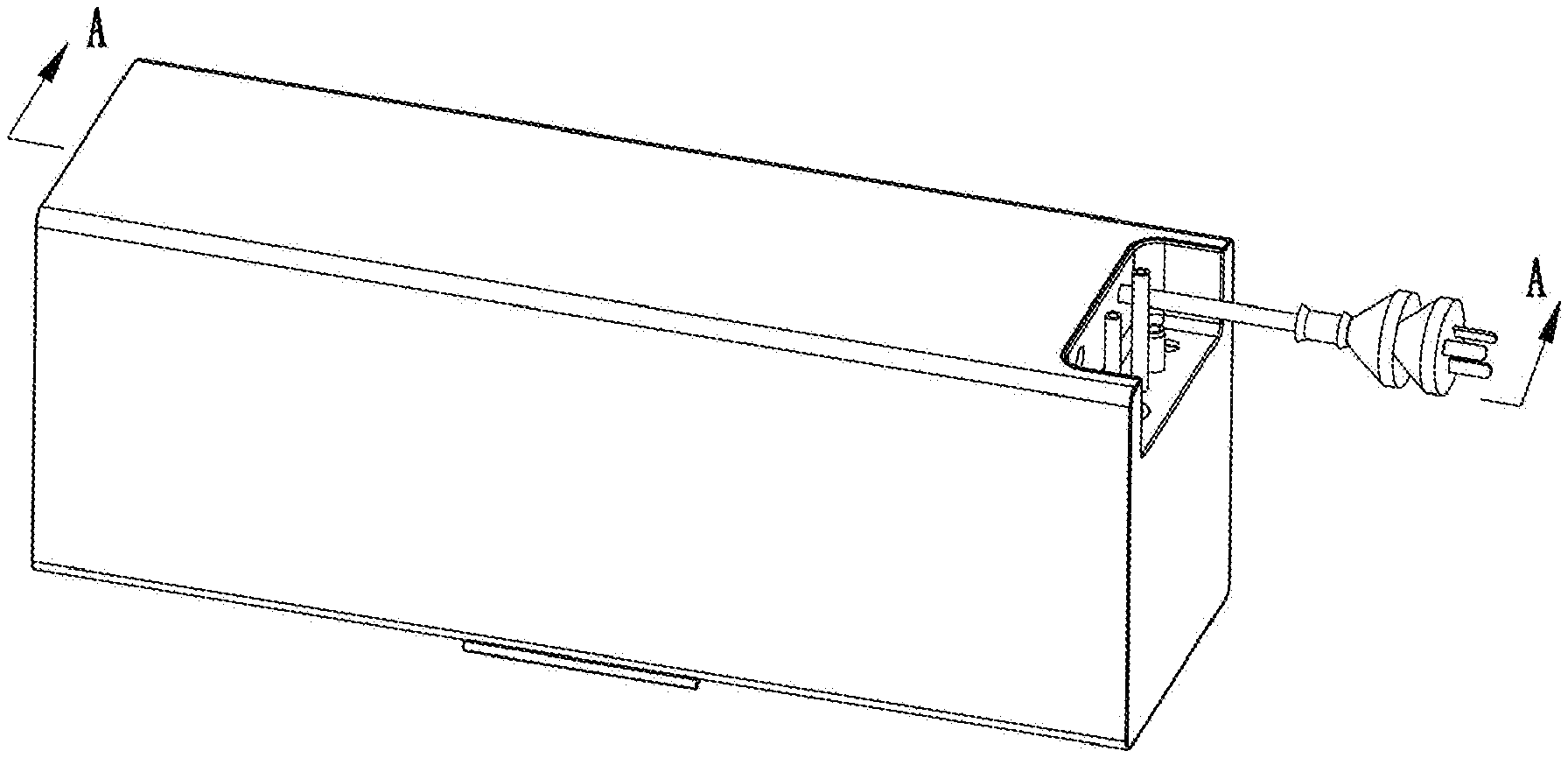
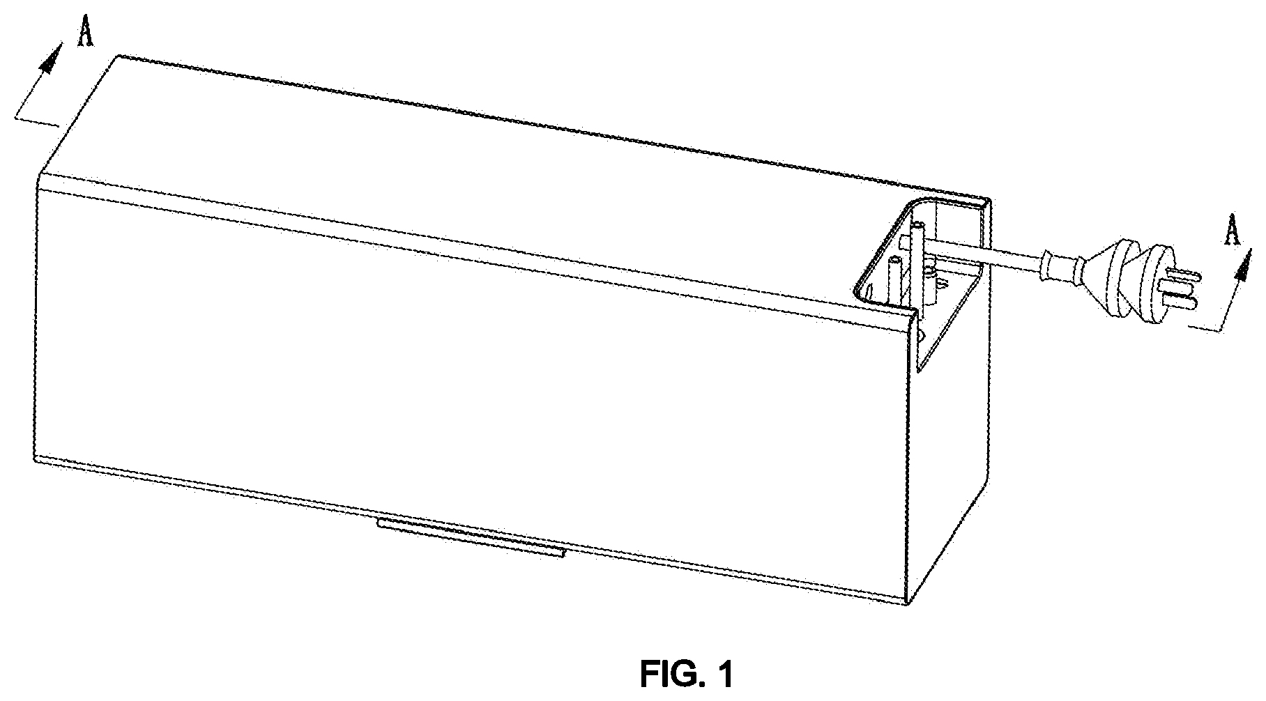
[0024] FIG. 1 is a schematic diagram of a horizontal water boiler according to one embodiment of the present disclosure.
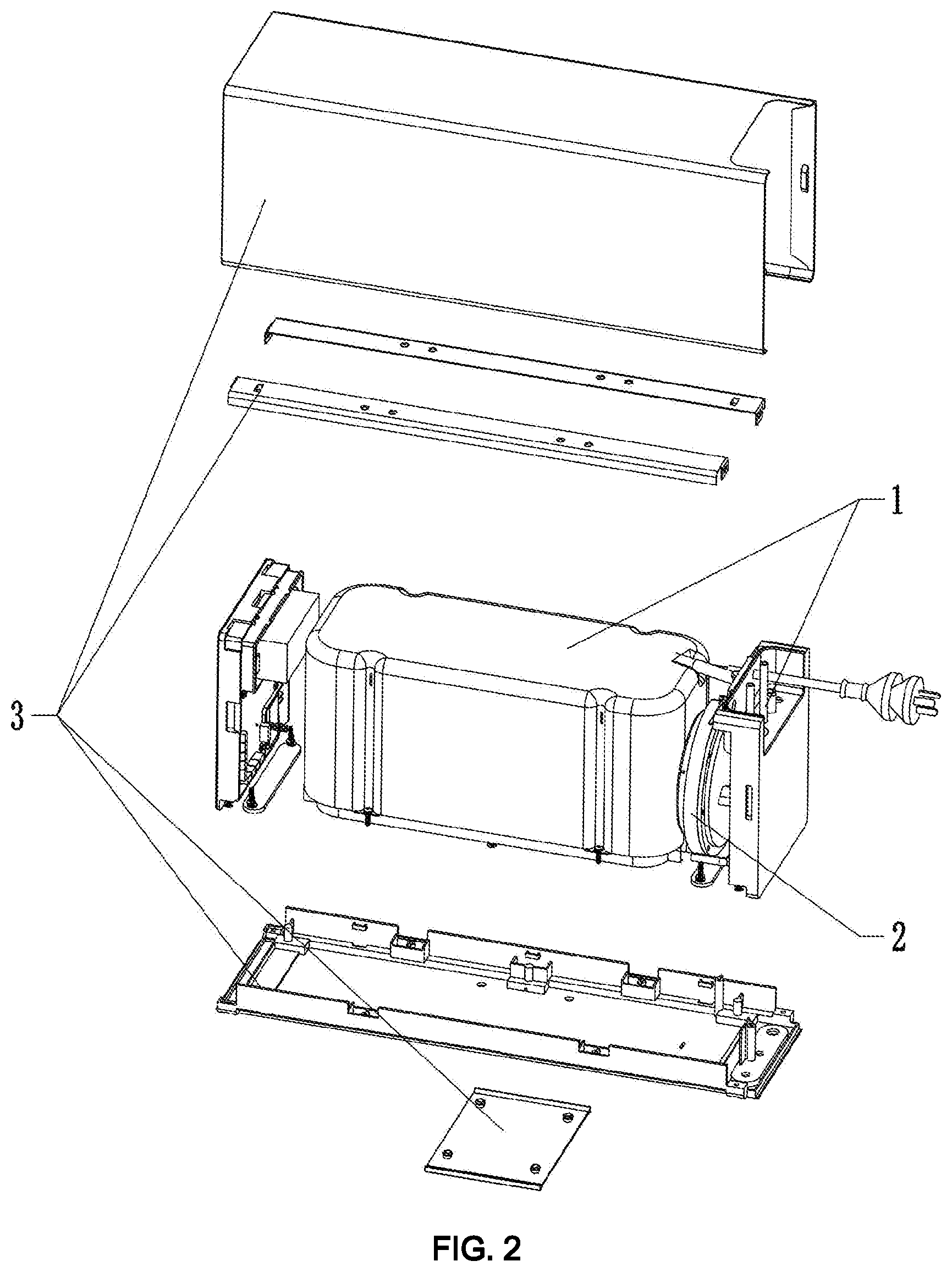
[0025] FIG. 2 is a first exploded view of the water boiler according to one embodiment of the present disclosure.
[0026] FIG. 3 is a second exploded view of the water boiler according to one embodiment of the present disclosure.
[0027] FIG. 4 is cross-sectional view of the water boiler according to one embodiment of the present disclosure.
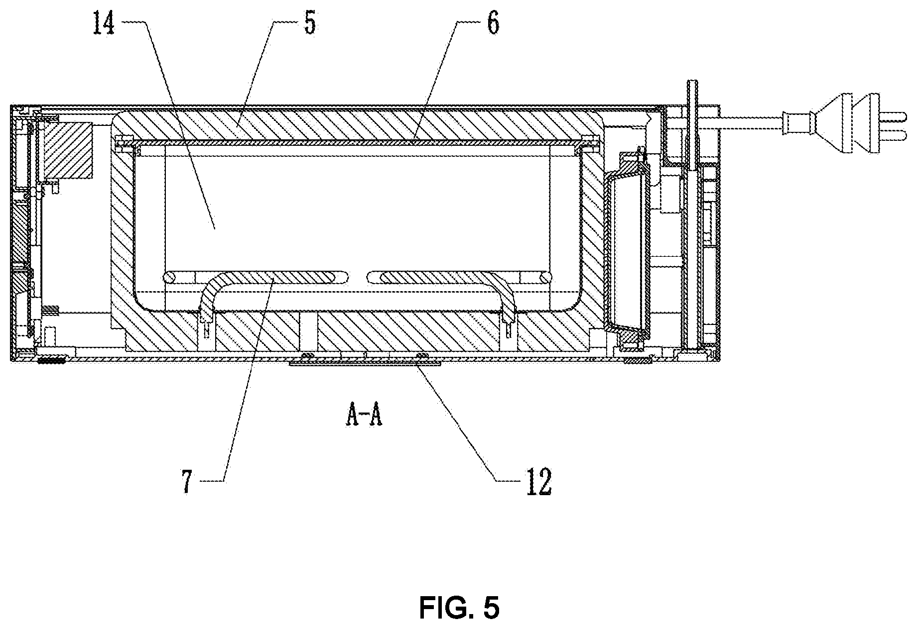
[0028] FIG. 5 is a cross-sectional view of the water boiler along lines A-A in FIG. 1.
DETAILED DESCRIPTION OF THE INVENTION
[0029] The present disclosure will be further described in detail below with reference to the drawings and specific embodiments, in order to better understand the objective, the technical solution, and the advantage of the present disclosure. It should be understood that the specific embodiments described herein are merely illustrative and are not intended to limit the scope of the disclosure.
[0030] It should be noted that when an element is referred to as being "fixed" to another element, it may be directly attached to the other element or a further element may be presented between them. When an element is considered to be "connected" to another element, it may be directly connected to the other element or connected to the other element through a further element (e.g., indirectly connected). The terms as used herein "vertical," "horizontal," "left," "right," "upper," "lower," and the like, are for illustrative purposes only and are not meant to be the only orientation.
[0031] Moreover, the terms "first" and "second" are used for descriptive purposes only and are not to be construed as indicating or implying relative importance or implicitly indicating the number of technical features indicated. Thus, features defining "first" and "second" may include one or more of the features either explicitly or implicitly. In the description of the present disclosure, the meaning of "a plurality of" is two or more unless specifically defined otherwise.
[0032] In the present disclosure, the terms "installation," "connected," "attached," fixed," and the like shall be interpreted broadly, and, for example, may be fixed, detachable, or integrated, unless otherwise explicitly defined. The term "connection" or "connect" could be a mechanical connection or electrical connection, and may be directly connected or indirectly connected through an intermediate medium. For those skilled in the art, the specific meanings of the above terms in the present disclosure can be conceivable.
[0033] In the present disclosure, the first feature "on" or "under" the second feature may include direct contact or indirect contact of the first and second features, unless otherwise specifically defined. Moreover, the first feature "above," "over," or "onto" the second feature includes the first feature directly or indirectly above or onto the second feature. The first feature "below," "under," or "beneath" the second feature includes the first feature directly or indirectly below or beneath the second feature, or merely the first feature level being less than the second feature.
[0034] With the development of technology and the improvement of living standards, waste disposer as a modern kitchen appliance has also been widely used. However, most of the water boilers available in the current market are vertical water boilers, which cannot meet the installation requirement of the waste disposer and has a complicated structure.
[0035] The disclosure will be further described accompany with the following figures and detailed embodiments.
[0036] As shown in FIGS. 1-5, in this disclosure, the horizontal water boiler comprises a tank assembly 1, an expansion assembly 2, a control assembly (no labeled), and a casing assembly 3 as follows.
[0037] (a) The tank assembly 1 comprises a tank body 9 having a water storage cavity 14, a tank cover 6, an insulation component 5 for preventing the passage of heat, a heating tube 7 for heating up water entering the water storage cavity 14, and a water flow assembly 19 for allowing water inflow and outflow. The water storage cavity 14 is paced horizontally. A first pipe 15 is located on a bottom of the tank body 9 and in communication with the water storage cavity 14. The tank body 9 further comprises a first opening which is in communication with the water storage cavity 14. The tank cover 6 comprises a second pipe 13 which is in communication with the water storage cavity 14. The tank cover 6 is configured for covering the first opening. The water flow assembly 19 comprises an inflow pipe 18 which is in communication with the first pipe 15, and an outflow pipe 17 which is in communication with the second pipe 13.
[0038] (b) The expansion assembly 2 comprises an expansion tank 16, which is connected to and in communication with the inflow pipe 18 and the outflow pipe 17.
[0039] (c) The control assembly comprises a temperature detector 8 located on the tank assembly 1 and configured for detecting a temperature of water within the water storage cavity 14.
[0040] (d) The casing assembly 3 is configured for supporting the tank assembly 1 and the expansion assembly 2. The casing assembly 3 comprises an installation portion 20 for connecting to a waste disposer.
[0041] Water from the outside can be introduced into the water storage cavity 14 through the inflow pipe 18 and the first pipe 15. The heated water can flow out from the second pipe 13 and the outflow pipe 17 for use. In some embodiments, the installation portion 20 is located on the bottom of the casing assembly 3, for facilitating the installation of the waste disposer.
[0042] More specifically, the first pipe 15 is used for water inflow, and the second pipe 13 is used for water outflow. The connection between the tank cover 6, and the second pipe 13 facilitates the installation of the water boiler greatly. It may increase the cleanliness of the water in the water storage cavity 14 by inletting the water from the lower part and outputting the water from the upper part. In some embodiments, the tank body 9 is horizontally arranged, and the casing assembly 3 comprises an installation portion 20 for attaching the waste disposer. The horizontally arranged tank body 9 not only increases the stability of the tank body but also creates enough side space for the installation of the waste disposer. Additionally, the horizontally arranged tank body 9 utilizes the side space of the water bath, so that the placement of the water boiler could be steadier. In some embodiments, the control assembly further comprises a chip component (not shown) and a display component (not shown). The temperature detector 8 and the display component both are electrically connected to the chip component, wherein the display component is configured to display a temperature information detected by the temperature detector 8 and a work status information of the tank assembly 1.
[0043] As shown in FIGS. 2-5, in some embodiments, the insulation component 5 is made of thermal insulation material and comprises a thermal insulation cavity. The tank body 9 and the tank cover 6 are both arranged within the thermal insulation cavity. In some embodiments, the insulation component 5 is made of polyurethane, and the tank body 9 is made of stainless steel.
[0044] As shown in FIGS. 3-5, in some embodiments, the heating tube 7 comprises two support pins. The heating tube 7 is arranged in the water storage cavity 14 with bilateral symmetry through the two support pins. The heating tube 7 has more stability and vibration of the water boiler during transportation can be significantly reduced. More specifically, as shown in FIG. 4, in some embodiments, the heating tube 7 has a curve structure. The curve structure is shaped as a Chinese character "". As shown in FIG. 3, in some embodiments, the tank cover 6 and the second pipe 13 are formed in integrity, and therefore the tank assembly 1 has a simpler structure.
[0045] As shown in FIG. 2, in some embodiments, the connection between the expansion tank 16 and the water flow assembly 19 are detachable. In other embodiments, the expansion tank 16 and the water flow assembly 19 are formed in integrally, and therefore reducing the complicity of the water boiler, and facilitating the installation of the water boiler. The expansion tank 16 is configured to absorb the expansion water, which is caused when the water in the tank assembly 1 is heated and expanded. The exist of the expansion tank 16 avoids the spillover of the heated water and protects the users from getting hurt.
[0046] As shown in FIGS. 2-5, in some embodiments, the casing assembly 3 comprises a casing seat 11, a casing cover 4, and a casing side plate. The casing seat 11 is configured to support and attach the tank assembly 1. As shown in FIG. 3 and FIG. 5, in some embodiments, the casing assembly 3 further comprises a grounded plate 12, which is located on and removable to the casing seat 11. As shown in FIG. 3, in some embodiments, the grounded plate 12 comprises an attachment clip 21. The casing seat 11 comprises a through hole adapted to the attachment clip 21. The grounded plate 12 is connected to the casing seat 11 via the coupling of the attachment clip 21 and the through hole.
[0047] As shown in FIG. 3, in some embodiments, the casing assembly 3 comprises a support plate 10, which is located on the bottom of the tank body 9 and extended through the insulation component 5. An overhang of the support plate 10 extending through the insulation component 5 is connected to the casing assembly 3. The support plate 10 and the tank body 9 are NI-Au welded, so as to reduce the effect of the welding on the tank body 9.
[0048] The above description is only preferred embodiments of the disclosure, and various modification and changes may be made by those skilled in the art within the spirit of the scope of the disclosure. Any modifications, equivalent substitutions, improvements made within the spirit and principles of the present disclosure shall be deemed within the scope of the present disclosure.
* * * * *
D00000
D00001
D00002
D00003
D00004
D00005
P00001
XML
uspto.report is an independent third-party trademark research tool that is not affiliated, endorsed, or sponsored by the United States Patent and Trademark Office (USPTO) or any other governmental organization. The information provided by uspto.report is based on publicly available data at the time of writing and is intended for informational purposes only.
While we strive to provide accurate and up-to-date information, we do not guarantee the accuracy, completeness, reliability, or suitability of the information displayed on this site. The use of this site is at your own risk. Any reliance you place on such information is therefore strictly at your own risk.
All official trademark data, including owner information, should be verified by visiting the official USPTO website at www.uspto.gov. This site is not intended to replace professional legal advice and should not be used as a substitute for consulting with a legal professional who is knowledgeable about trademark law.