A Compact Heat Recovery Ventilation System
LOPATINSKY; Edward ; et al.
U.S. patent application number 16/089431 was filed with the patent office on 2020-09-24 for a compact heat recovery ventilation system. The applicant listed for this patent is INDUSTRIAL DESIGN LABORATORIES INC., Loftsson JOHANNES, Edward LOPATINSKY, Daniel SCHAEFER. Invention is credited to Loftsson JOHANNES, Edward LOPATINSKY, Daniel SCHAEFER.
| Application Number | 20200300498 16/089431 |
| Document ID | / |
| Family ID | 1000004916268 |
| Filed Date | 2020-09-24 |
View All Diagrams
| United States Patent Application | 20200300498 |
| Kind Code | A1 |
| LOPATINSKY; Edward ; et al. | September 24, 2020 |
A COMPACT HEAT RECOVERY VENTILATION SYSTEM
Abstract
A countercurrent heat recovery ventilation system includes an air module assembly and heat exchanger assembly. Air module assembly made from front and back panels connected by two side panels, base plate fixed with the side panels and placed parallel between side panels and a double side radial impeller with a shaft, an electric drive form two hydraulically isolated flow canals with inlet and outlet openings. The heat exchanger assembly comprises a heat-exchanger that could be done as changeable flow side heat-exchanger made as folded corrugated fins or plates, thus each of the both flow passages split in separate flow channels. Every other channel is sealed to flow from flow same direction forcing the flow to be in opposite direction in all adjacent cannels. This forms two hydraulically isolated flow passages with intake and outtake openings connected respectively with outlet and inlet openings of the air blower assembly.
| Inventors: | LOPATINSKY; Edward; (San Diego, CA) ; SCHAEFER; Daniel; (Kanarraville, UT) ; JOHANNES; Loftsson; (Reykjavik, IS) | ||||||||||
| Applicant: |
|
||||||||||
|---|---|---|---|---|---|---|---|---|---|---|---|
| Family ID: | 1000004916268 | ||||||||||
| Appl. No.: | 16/089431 | ||||||||||
| Filed: | March 29, 2017 | ||||||||||
| PCT Filed: | March 29, 2017 | ||||||||||
| PCT NO: | PCT/US2017/024865 | ||||||||||
| 371 Date: | September 28, 2018 |
Related U.S. Patent Documents
| Application Number | Filing Date | Patent Number | ||
|---|---|---|---|---|
| 62316325 | Mar 31, 2016 | |||
| Current U.S. Class: | 1/1 |
| Current CPC Class: | F04D 25/08 20130101; F24F 12/006 20130101; F04D 25/06 20130101; F04D 25/16 20130101 |
| International Class: | F24F 12/00 20060101 F24F012/00; F04D 25/06 20060101 F04D025/06; F04D 25/08 20060101 F04D025/08; F04D 25/16 20060101 F04D025/16 |
Claims
1. A compact heat recovery ventilation system comprising an air module assembly with exhaust gas inlet, exhaust gas outlet and fresh gas inlet, fresh gas outlet, heat exchanger assembly with exhaust gas intake, exhaust gas outtake and fresh gas intake, fresh gas outtake, wherein: said air module assembly comprises two side panels, base plate placed between two radial blowers surrounded by airflow guides and located on a common axis between each said side panel and said base plate forming two hydraulically isolated counter flow canals between said exhaust gas inlet and said exhaust gas outlet and between said fresh gas outlet and said fresh gas inlet. said heat exchanger assembly comprising heat exchange elements surrounded by outside panels with two open ends, each of said open end divided by a center plate to two separated isolated flow conduits with said exhaust gas intake, said exhaust gas outtake and said fresh gas outtake, said fresh gas intake, where said fresh gas outtake of said conduit hydraulically connected to said fresh gas inlet of said canal and said exhaust gas intake of said conduit hydraulically connected to said exhaust gas outlet of said canal.
2. The compact heat recovery ventilation system per claim 1 wherein said side panels are parallel to said base plate.
3. The compact heat recovery ventilation system according to claim 1 wherein said base plate of the air module assembly made from two plates divided in plane perpendicular to the thickness of said base plate.
4. The compact heat recovery ventilation system according to claim 1 wherein said base plate is parallel to the said outside panels and the center plate.
5. The compact heat recovery ventilation system according to claim 1 wherein said side panels are directly connected to said outside panels to form substantially continuous surfaces and said base plate is directly connected to said center plate to form a substantially continuous plate.
6. The compact heat recovery ventilation system according to claim 1 wherein the air module assembly connected to heat exchanger assembly through a flat transition with two airflow ducts.
7. The compact heat recovery ventilation system according to claim 1 wherein the air module assembly connected to heat exchanger assembly through a L-shape transition with two airflow ducts.
8. The compact heat recovery ventilation system according to claim 1 wherein said compact heat recovery ventilation system is hidden within a structure envelope inside a building wall, a window frame or a ceiling.
9. The compact heat recovery ventilation system according to claim 1 wherein said system includes two said radial blowers each comprising a radial impeller, said impellers integrated with electric drive and each said impeller spaced from the respective side of said base plate, each of said radial impellers located at one of said canals.
10. The compact heat recovery ventilation system according to claim 9 wherein each of said radial impellers comprises set of radial blades fixed on a back plate disk placed in a cylindrical cavity of said base plate.
11. The compact heat recovery ventilation system according to claim 10 wherein each of said back plate made from ferrous metal.
12. The compact heat recovery ventilation system according to claim 10 wherein at least one of the back plates includes set of permanent magnets and along with second said back plate comprises a rotor of said electric drive.
13. The compact heat recovery ventilation system according to claim 9 wherein said electric drive comprises a flat stator made as circumferential arrayed coil windings with magnetic axes perpendicular to a plane of said flat stator and integrated with said base plate, while said magnetic elements made as circumferential arrayed permanent magnets magnetized perpendicular to the plane of said flat stator, thus magnetic axes said coils windings and said magnets are substantially parallel.
14. The compact heat recovery ventilation system according to claim 9 wherein a stator of said electric drive made as a stator comprising circumferential arrayed coils windings with magnetic axes coincided with a plane of said stator and fixed with said base plate and when electrically powered, creates alternating electromagnetic fields which interact with a said permanent magnets of said rotor thus providing a rotation of said two radial impellers.
15. The compact heat recovery ventilation system according to claim 13 wherein the flat stator located between two said divided sections of the said base, thus said cylindrical cavities, said stator and said back plates of the rotor creating a labyrinth hydraulically isolating said two canals of said air module assembly.
16. The compact heat recovery ventilation system according to claim 12 wherein outside diameters of said rotors are larger than diameters of said blades of the radial impellers.
17. The compact heat recovery ventilation system according to claim 9 wherein at least one of said radial impellers is a cross flow type.
18. The compact heat recovery ventilation system according to claim 9 wherein both of said radial impellers are the cross flow type.
19. The compact heat recovery ventilation system according to claim 9 wherein both of said radial impellers rotate in one direction.
20. The compact heat recovery ventilation system according to claim 17 wherein said crossflow impeller further comprises at least one guide vane surrounded by said radial blades;
21. The compact heat recovery ventilation system according to claim 1 wherein said heat exchanging elements protruding from both sides of said center plate up to said outside panels.
22. The compact heat recovery ventilation system according to claim 1 wherein said heat exchanging elements shaped as corrugated fins made as a plurality of channels divided by said center plate to one said intake and one said outtake openings at one said open end and one said outtake and one said intake openings at the other said open end in a way that every even channel of said corrugated fins is sealed at said intake openings while every odd channel is sealed at said outtake openings on said another, thus every other channel is having opposite flow direction to every neighboring channel.
23. The compact heat recovery ventilation system according to claim 21 wherein said center plate has a flat portion across all said corrugated fins and a plurality dividers perpendicular to said flat portion and spaced with a double distance of the distance between neighboring said corrugated fins thus each said divider would seal every other said corrugated fin at said intake.
24. The compact heat recovery ventilation system according to claim 22 wherein said center plate has a flat portion across all said corrugated fins and a plurality dividers perpendicular to said flat portion and spaced with a double distance of the distance between neighboring said corrugated fins thus each said divider would seal every other said corrugated fin at said outtake.
25. The compact heat recovery ventilation system according to claim 1 wherein said heat exchanging elements made from plurality of even and odd plates forming plurality of said channels and said center plate that has a flat portion across all said plates from both said open ends and at one said open end at said intake each pair of said even and said odd plates bended towards each other and sealed and at another said open end at said intake each pair of odd and even said plates bended towards each other and sealed and at one said open end at said outtake each pair of said odd and said even plates bended towards each other and sealed and at another said open end at said outtake each pair of said even and said odd plates bended towards each other and sealed.
26. The compact heat recovery ventilation system according to claim 24 wherein central portion of said plates at the both said open ends has a bend perpendicular to the plate creating said center plate across all said channels thus separates the intakes and outtakes and any said channel is having opposite flow direction to every next said channel.
27. The compact heat recovery ventilation system according to claim 2, wherein the common axis of the radial blowers is perpendicular to the side panels.
28. The compact heat recovery ventilation system according to claim 1 wherein at least one of said radial blowers is a cross flow type.
29. The compact heat recovery ventilation system according to claim 1 wherein both of said radial blowers are the cross flow type.
30. The compact heat recovery ventilation system according to claim 1 wherein both of said radial blowers rotate in one direction.
Description
[0001] The present application claims the benefit of priority of U.S. Provisional Patent Application No. 62/316,325, filed Mar. 31, 2016 the entire context of which is incorporated herein by reference.
FIELD OF THE INVENTION
[0002] The present invention relates generally to heat ventilation and air conditioning (HVAC) systems for moving air, and/or regulating the temperature, humidity, chemistry and quality of indoor air. More particularly, the present invention relates to air processing devices such as ventilators, including heat ventilators, coolers, air conditioners humidifiers and air purifiers. The present invention is particularly, but not exclusively, useful for systems that are mounted inside a wall or ceiling and constitute a part of room decor; therefore, thickness of the system is a critical factor. Another critical factor is the countercurrent air flow (air flowing in opposite directions) that provides the highest energy recovery efficiency or chemical recovery efficiency. There is also an important field of application related to the indoor automotive air ventilation/conditioning systems.
BACKGROUND OF THE INVENTION
[0003] The countercurrent principle is a vital factor in many ventilation processes. Heating or cooling energy in the exhaust air can be preserved by recovering it and directing it into the replacement air through a heat exchanger. Low indoor humidity levels can also be better maintained in hot and humid environments by extracting the humidity out of the supply air into the exhaust air through various countercurrent processes (like desiccant wheel, water permeable membrane etc.). Same method can be used to help maintain sufficient high indoor humidity level by extracting much of the humidity from the exhaust air into the supply air. Some industrial processes can also benefit from using an extraction method based on a countercurrent (or cross-current) principle, in order to minimize pollution or waste, or to make the process more efficient.
[0004] In addition to these countercurrent processes, good ventilation systems can also have various other air processing units, such as filters including activated carbon, humidifier, dehumidifier, heater, cooler and others, which may improve the quality of air, while a long duct system may be necessary to efficiently extract or supply the air in the right locations. All these processes and systems (countercurrent, cross-current or in-line) restrict the airflow and contribute to the pressure drop of the ventilation system. Ambient pressure fluctuations due to weather or movement of an enclosure is another source of the pressure load that requires additional power consumption for ventilation system.
[0005] However, higher power often results in higher sound level, which is one of the reasons why more powerful systems are centralized with long bulky ducts and noisy blowers that need to be closed off in a sound insulated enclosure.
[0006] This brings up one of the major problems for modern ventilation systems. The powerful ventilation systems are often too bulky, and the small ones are often not powerful enough. Other disadvantages of the smaller systems of lower functionality are that most designs are difficult to conceal, the small size results in higher motor and blower inefficiency and, as they are closer to the user, their noise level can still be a nuisance.
[0007] This dilemma causes a problem, specifically in projects, where there is only limited space available for the ventilation system, for instance, when older apartments or buildings are being renovated. In these very common cases, there are often simply no good solutions possible.
[0008] Most of the current Heat Recovery Systems have traditional axial fans, which are often used as air moving devices, have certain limitations because they are not suited to create high static pressure at given airflow when various air processing units are added (heat exchanger, filter etc.) and when affected by ambient pressure fluctuations (e.g., wind loads, vacuum pressure inside the building envelope). Such designs are described in the International Patent Application WO 2005/040686 "Window Type Air Conditioner" and Patent WO2012155913 "Ventilation system with a rotatable air flow generator and one or more moveable registers and method for obtaining ventilation through the ventilation system."
[0009] There are also numerous designs of air processing devices for HVAC systems that include radial type blowers as air moving devices, for example, US Patent Application 2005/0257687. Radial blowers for indoor air processing devices create sufficient static pressure at a given airflow, but have relatively small diameter of the impeller. It is well known that for such diameters, the total blower efficiency decreases dramatically. When a flat centrifugal blower is mounted flat on the surface in such way that it fits the structural envelope, the whole design is limited by the suction being in the center on the flat side and, therefore, perpendicular to the structural envelope. This leaves little room for any noise mitigation, like a silencer, unless by compromising the flat design.
[0010] Crossflow blowers are used in air processing devices more often due to their affordable mounting performance and a well-known ability to achieve relatively high efficiency that does not depend upon diameter size. Moreover, the crossflow blower creates much more static pressure at the same airflow, unlike the centrifugal blower, when other conditions are equal. There are many such designs, for example, International Patent Application WO 2004/085929 "Indoor Unit for Air Conditioner" and Japanese Patent No. JP2000297945 "An Air Conditioner". According to these designs, air processing devices comprise a base with a flat surface for wall mounting and the axis of the crossflow blower is parallel in respect to that surface. However electric motors for typical crossflow blowers are located adjacent to the impellers, because if a conventional electric motor is placed inside the impeller, it greatly affects the internal aerodynamic structure of the crossflow blower, thus dramatically decreasing performance characteristics.
[0011] In some cases it may be beneficial to have two blowers rotate on the same axis. Having a single motor rotate two blowers increases the ventilation efficiency benefits, as larger motors are normally more efficient. An example of one such solution is described in the US patent application 2013/0101449(A1) "Double inlet centrifugal blower with peripheral motor", where a peripheral motor is used to run two concurrent blowers on a single axis.
[0012] Similar solution is also described in a Japanese patent application 60-75635 "Heat exchanging type fan," consisting of a casing and two centrifugal fans mounted on the same shaft inside the casing, but oriented in opposite directions in regard to each other, creating concurrent flow through a heat exchanger. Two co-current channels for heat carriers of different temperatures are formed in the casing, separated by a partition separating both fans. The heat exchange element comprises radial fins mounted on both surfaces of the partition beyond the edges of the impellers of the fans.
[0013] When the fans rotate, the heat carriers enter the inter-blade space of the fans via the suction inlets and further on, passing over both sides of the radial fins of the heat exchange element, are removed from the casing via the respective blower outlets. Heat exchange takes place through the radial fins and the partition itself, but as the flow is co-current, the efficiency is limited. Again a large radial size, inlet perpendicular to the plane and co-current flow should be listed among the disadvantages of such arrangement. A heat exchanger solution for co-current airflow in two channels is described in U.S. Pat. No. 7,837,127 B2 "Ventilation system." This system overcomes the disadvantages of the co-current airflow by using a very thin "thin wire" heat exchanger, which effectively creates a countercurrent heat exchanger between the channels. The countercurrent fix of the otherwise co-current system has some disadvantages that may limit its use. The heat exchanger relies on using copper wire, resulting in higher cost and low pressure drop over the heat exchanger may cause higher sensitivity to pressure fluctuations.
[0014] Modern air processing devices have become a part of indoor interior as a wall-mounted system, creating a requirement for thin box-shaped designs, within the structural envelope. However, all known designs do not provide a thin air processing device with the crossflow blower for such wall-mounted air movement systems. The thickness of known devices with the crossflow blower axis parallel to the mounting surface is defined by the impeller diameter. Such solutions are thicker than desired and they do not meet the market requirements.
[0015] There is a main problem for all known air processing-heat exchanger devices where they cannot resolve the contradiction between the high performance that requires a relatively large impeller diameter on one hand and a small thickness of the whole device on the other hand.
[0016] Therefore, it is generally desirable to provide a thin, box-shaped air processing device for indoor HVAC systems with thin size relatively large diameter efficient blower unit that produces countercurrent air flow that overcomes such problems in a mechanically feasible manner.
[0017] Heat-exchanger is one of the most important part of the countercurrent heat recovery ventilation system.
There are at least a few options that could be used for this proposed application such as:
[0018] traditional one made as a central plate with protruded fins or pins from both sides of the center plate. As the center plate forms separation between the two countercurrent air streams along the length of the heat exchanger, the flow is restricted to exit on the other end of the heat exchanger on the same side as it entered.
[0019] changeable air flow sides could be made in the following ways: designed as folded fins with a center plate divider, or as plate heat exchanger based on the same principals as changing air flow sides. The center plate dividers are only located at the open ends of the heat exchanger but not inside it. This gives additional flexibility in design as the air is free to move between one side of the outside panel at the intake of heat exchanger, to the opposite side of outside panel at the outtake of heat exchanger. In the same time the airstream is separated to plurality of thin airstreams moving in a way that any other thin stream flows in opposite direction.
[0020] The last design of such heat exchanger is described in patent DE4301296 "Plate heat exchange on countercurrent principle" and incorporated here by reference.
[0021] Space for the air filter unit in most current systems are included as part of the HVAC treatment box.
[0022] There are some building solutions which are having ventilation ducts integrated into a wall, a slab or a raised floor. Such solutions are described in patents US 2008 0142610(A1) "Integrated structural slab and access floor HVAC system for buildings ",KR Patent 2010 0002817 (A)"Slab structure" and KR patent 2015 101576615 (B1) "Hollow core slab integrated ventilation deck plate". There is, however, too little space for air processing units, and blower inside these slabs.
[0023] Efficient motor is very important part for any heat recovery system as the part that providing energy saving. Several improvements for better motor efficiency level have been done according to US Patent 2004 245866 (A1) "Integrated cooler for electronic devices," which describes a flat cooling unit consisting of crossflow blower connected to heatsink removing heat from a co-current flow around heat pipes. US Patent 2005 121996A1 "Electric dive for radial impeller" describes a flat peripheral motor with coils printed on a PCB board and magnetic means fixed with the radial impeller and even integrated in the blades. This compact design has high efficiency which is increased further by leaving space in center of the radial blower allowing higher airflow. US patent 2006 0006745A1. "Integrated blower for cooling device" describes a peripheral motor for a radial blower with stator and rotor in the same plane. This arrangement produces lower motor vibration, which results in lower motor noise, higher efficiency and ensures higher airflow. US patent 2006 238064A1 "Flat radially integrated electric drive and method of the manufacturing the same", describes stator of the motor printed in a PCB board where the motor and the rotor are on the same plane. US 2006 056153 A1 "Multi-heatsink integrated cooling device," describes flat crossflow cooler connected to two heat sinks. US Patent 2008 101966A1 "High efficient compact radial blower" describes an integrated blower, motor and heat sink, which uses printed coils, and locates the heat sink inside the blower. US Patent 2007 166177(A1) "Thin air processing device for heat ventilation air conditioning system", describes an efficient design for a single flat cross flow blower and the benefits of connecting it to an air processing unit like purifier, humidifier or temperature regulating means. US Patent 2008 238218(A1) describes an improved method of arranging coils in motor partially printed on a PCB board. This arrangement increases the motor power, and efficiency.
[0024] All these prior art designs still have some disadvantages that limited abilities to create flat compact heat recovery system capable to be soundless, wall-mounted or even fit inside of the wall or ceiling. It would be highly desirable to use the advantages of the known prior art along with the novelty elements that would be described further per our patent application.
SUMMARY OF THE INVENTION
[0025] The present invention is an approach to resolve in particular situations where only limited space is available for ventilation system, by inventing a ventilation system that can easily be integrated into the structural envelope of an enclosure (building, car, boat, plane or similar). Such configuration is achieved herein by a system, based on the countercurrent principle, with flat countercurrent heat exchanger and flat blowers powerful enough to perform and the system thin enough to fit inside the wall or ceiling.
[0026] Using a flat countercurrent ventilation system made up of matching flat air treatment modules which all have identical thickness and width and for different countercurrent air treatment processes, provides novelty of the design.
[0027] An additional benefit of the compact flat system of the invention, is that the system's length does not have to be restricted. Any air handling unit which has the same thickness and width can be added to the system without compromising aesthetics or style of the system. This gives the system additional functional flexibility (modularity), as each of the air treatment modules can be chosen independently so that it can meet its functional requirements, thus allowing for additional flexibility in design.
[0028] According to the present invention, the whole heat recovery system is made from two major components, namely a air module assembly and heat exchanger assembly.
[0029] The air module assembly comprises two radial blowers surrounded by airflow guides, placed on the common axis using peripheral motor. Housing made from two side panels and base plate between these side panels. These blowers along with airflow guides, side panels and base plate form two hydraulically isolated counter flow canals with inlet and outlet openings for each of the canal.
[0030] Heat exchanger assembly comprises a box with heat exchange elements surrounded by outside panels. The box, further compromises an intake and outtake openings and a center plate dividing the whole heat exchanger assembly in two hydraulically isolated flow conduits with intake and outtake openings. Side panels of the air module assembly are fixed with outside panels of the heat exchanger. Base plate of the air module assembly is fixed with center plate of the heat exchanger assembly. Therefore, such arrangement allows hydraulically connecting canals of the air module assembly to flow conduits of heat exchanger assembly respectively.
[0031] The air module assembly comprises a base plate fixed with the side panels thru airflow guides and placed parallel between the side panels.
[0032] Two radial blowers are spaced between side panels from both sides of the base plate, while the other part of the base is fixed to the center plate of the heat exchange assembly. Two radial blowers further comprise two radial impellers spaced from both sides of the base plate, thus each of the radial impellers is located at one of flow passages. Each of the radial impellers comprises a back plate disk with radial blades that are spaced apart.
[0033] Heat exchanging elements protruding from both sides of the base plate thus spaced inside of each flow passages are forming an exhaust and fresh heat-exchanging sides of the integrated heat exchanger.
[0034] The heat-exchanger could also done as changing flow side heat-exchanger made as folded fins or plates, thus each of the both flow passages split in many separate flow channels. Every other channel forcing the flow in the opposite direction.
[0035] The electric drive preferably comprises a flat stator fixed attached to the base plate, and a rotor with magnetic elements integrated with at least one of the back plate disk, thus the double side radial impeller serves as the rotor of the motor. The stator size (diameter) is larger than the radial blower diameter, when electrically powered, creates alternating electromagnetic fields that interact with a magnetic field created by the magnetic elements, thus providing a rotation of the double side radial impeller, causing the exhaust gas flow through the outtake side of the heat exchanger, while fresh gas flows through the intake side of the heat exchanger.
[0036] The base plate of the air module assembly further comprises volute casings for each of the radial impeller, that formed by flow guides protruding from both sides of the base plate, one of the two flow guides serves as a tongue of the volute casing, while the other flow guide serves as a spiral part.
[0037] According to the first embodiment, one of the inlet opening (exhaust gas out) is located at the side panel, both radial impellers rotate in one direction and one of the radial impellers operates as a centrifugal blower, while the other radial impeller operates as a crossflow blower. At the same time, the flow guides of the centrifugal blower serve as the volute casings directing the airflow for one part of the flow canal. The flow guides on other of base plate create the second flow canal made by crossflow blower.
[0038] The Heat Exchanger assembly includes heat exchanging elements located in the line of the intake and the outtake openings in a consecutive way for the flow conduits, thus providing counter-flow heat exchange process. In this case, the electric drive can be made as a conventional electric motor spaced inside of the radial impeller of the centrifugal blower.
[0039] According to the second embodiment of the present invention, the radial impellers rotate in one direction and operate as crossflow blowers, two flow guides are shifted in view perpendicular to the shaft in angular direction, therefore the fresh gas flows through the intake openings, the heat exchanging elements, inlet, the crossflow impeller and the outlet openings in a consecutive way, while other air flows through the inlet openings, the radial impeller, intake of the heat exchanging elements, outtake in a consecutive way form another flow passage, thus providing countercurrent flow heat exchange process. In this case the electric drive can be made as a peripheral thin motor placed between crossflow impellers.
[0040] The heat exchanger assembly can further comprise the heat exchanging elements, thus forming two elongated flow passages serving as the exhaust and fresh sides of the integrated heat exchanger.
[0041] The heat exchanging elements for all embodiments can be made in a few ways:
[0042] In the most general configuration, when heat exchanging elements protruding from both sides of the center plate thus spaced inside of each flow passages form an exhaust and fresh heat-exchanging sides of the integrated heat exchanger.
[0043] The heat-exchanger could also be built as changing flow side heat-exchanger made as folded fins or plates, thus both flow passages split in plurality of flow channels. Every other channel would be forcing the flow in opposite direction.
[0044] The last approach is the most beneficial for our proposed application since the air passages are changing sides inside of the system, thus when the system is installed in the wall or ceiling, the air from the inside of the enclosure travels towards outside of the enclosure naturally, with no special ducts.
[0045] A preferred heat-exchanger for this design is per patent DE 4301296 A1 with some improvements described further.
[0046] Several design options for the electric drive can be used here in accordance with the invention. According to one design option the flat stator comprises circumferential arrayed coil windings with magnetic axes coincided with a plane of the flat stator and integrated with the base plate, while the magnetic elements made as circumferential arrayed permanent magnets are placed and magnetized along the plane of the flat stator, thus magnetic axes of the coil windings and the permanent magnets are located at one plane substantially.
[0047] For all embodiments, when the radial impellers are operating, as crossflow blowers including guides integrated with the side panels correspondingly, the exhaust air flows through the intake opening, the heat exchange elements, the radial impeller, and the outlet openings in a consecutive way for one airflow passage while the other airflow passage of the fresh air flows through inlet opening, radial impeller, heat exchange elements and outtake opening.
[0048] The foregoing and other objectives, features and advantages of the invention will be more readily understood upon consideration of the following detailed description of the invention, in conjunction with the accompanying drawings.
BRIEF DESCRIPTION OF THE DRAWINGS
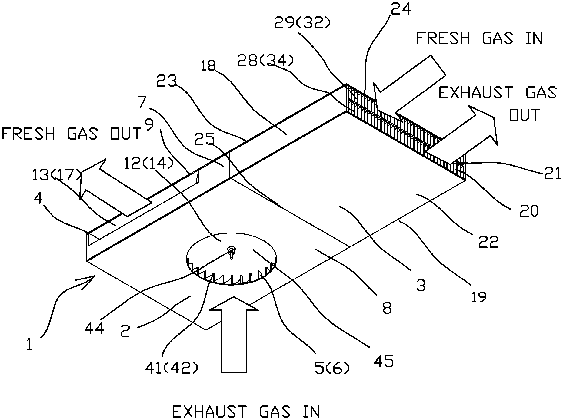
[0049] FIG. 1 is a perspective view showing the first embodiment of the compact heat recovery ventilation system for the present invention containing one centrifugal and one crossflow blower. (ducts and filters are not shown)
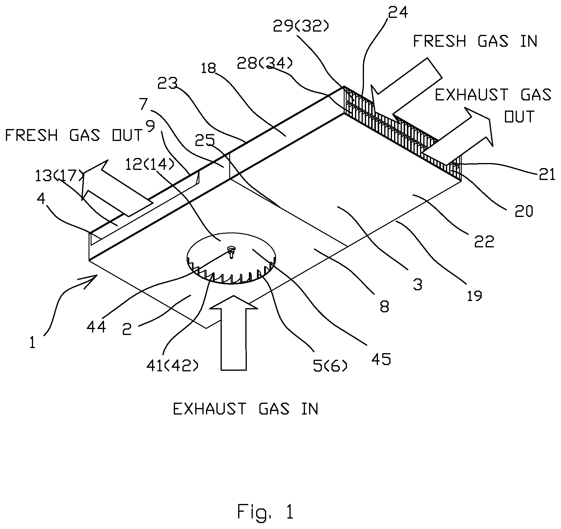
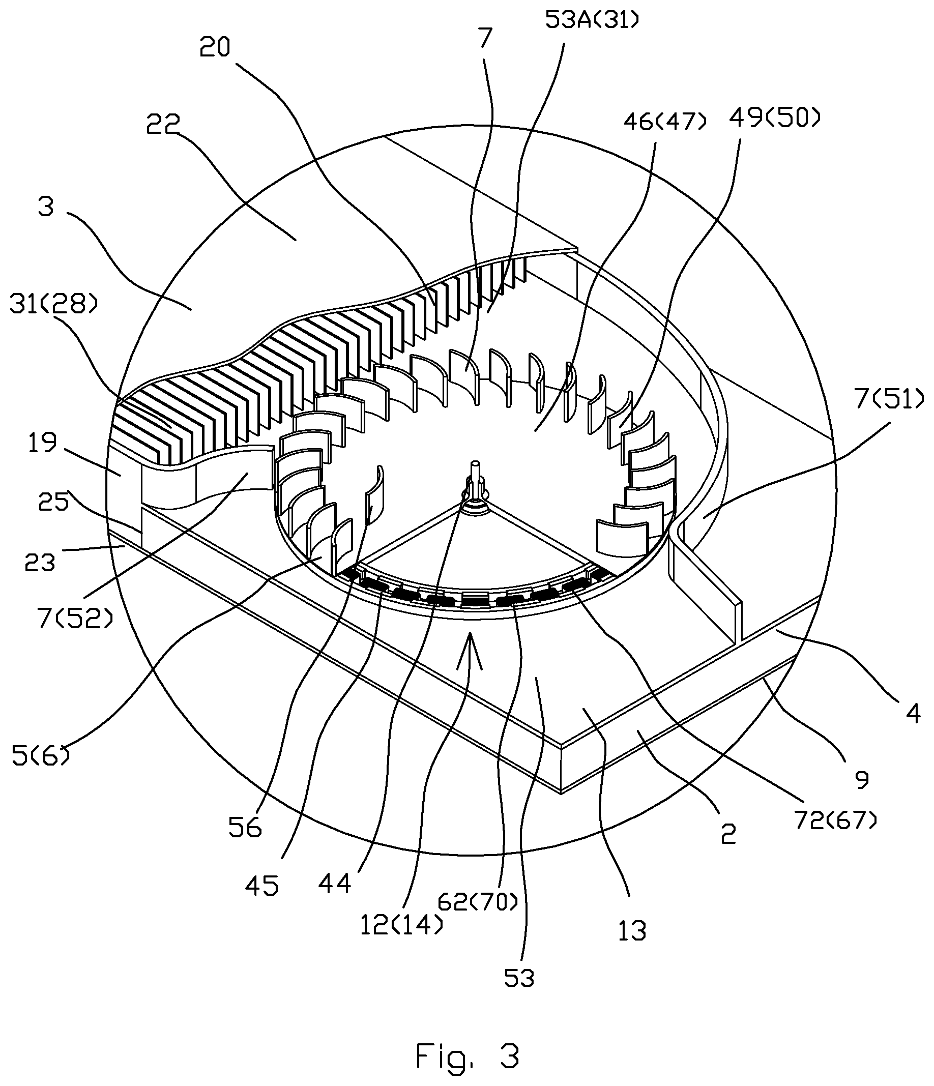
[0050] FIG. 2 is a perspective view showing the second embodiment of the compact heat recovery ventilation system for the present invention containing two crossflow blowers. (ducts and filters are not shown).
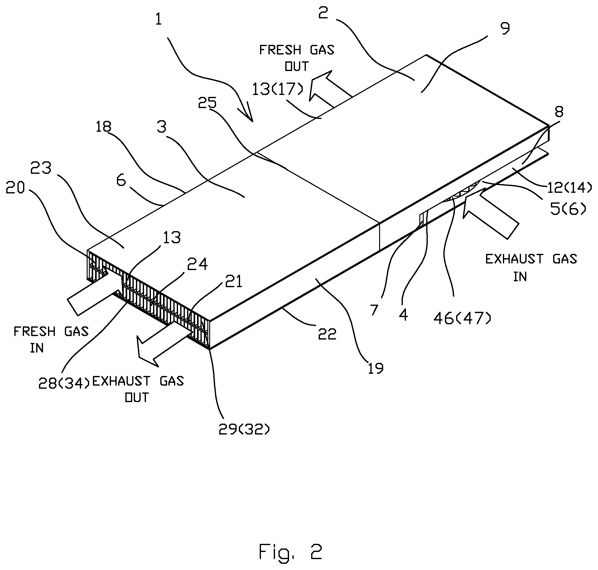
[0051] FIG. 3 is an exposed view of one of the crossflow blowers from FIG. 2 that shows the integrated crossflow blower including motor elements.
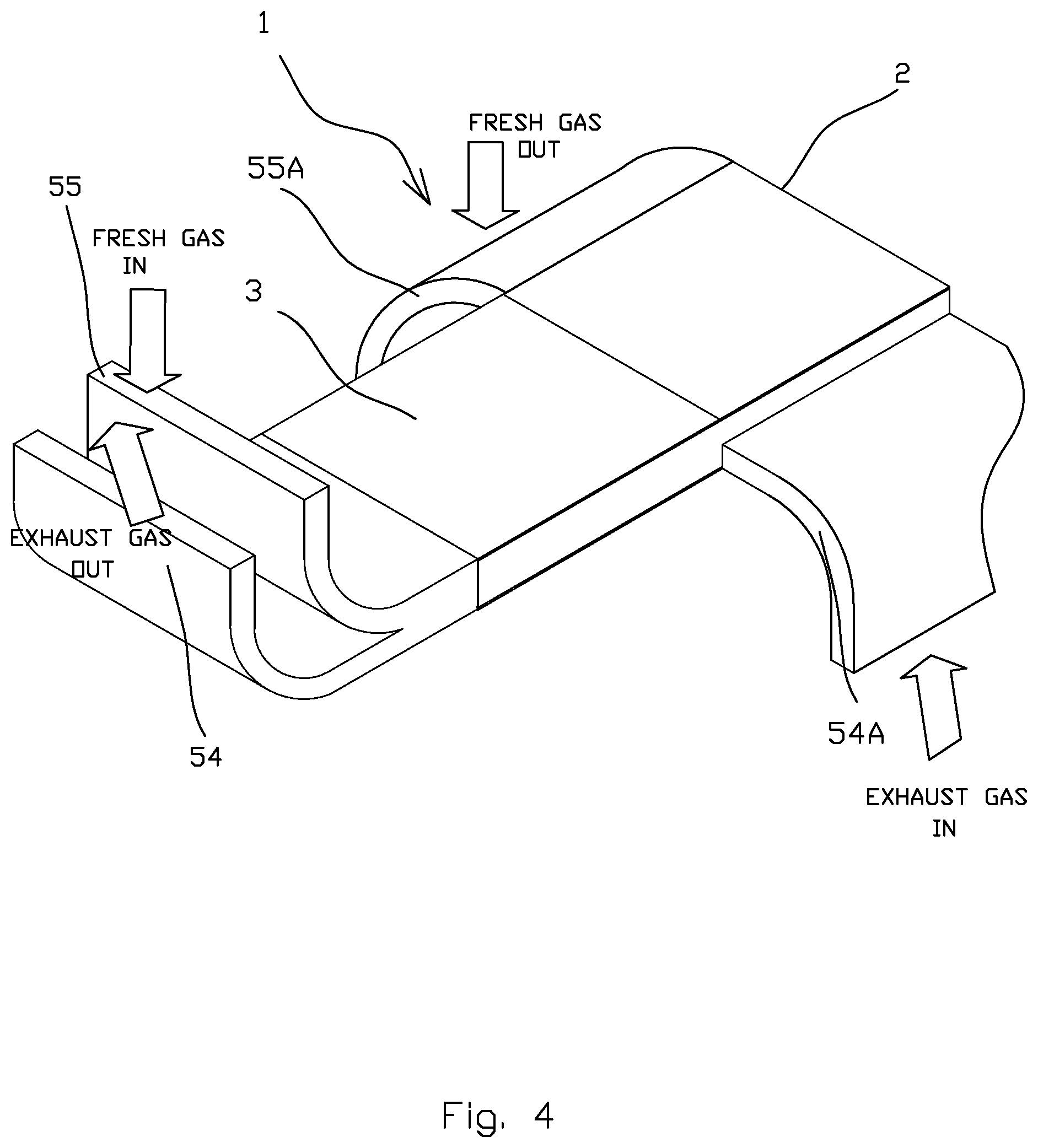
[0052] FIG. 4 is perspective view showing the second embodiment of the current invention including ducts.
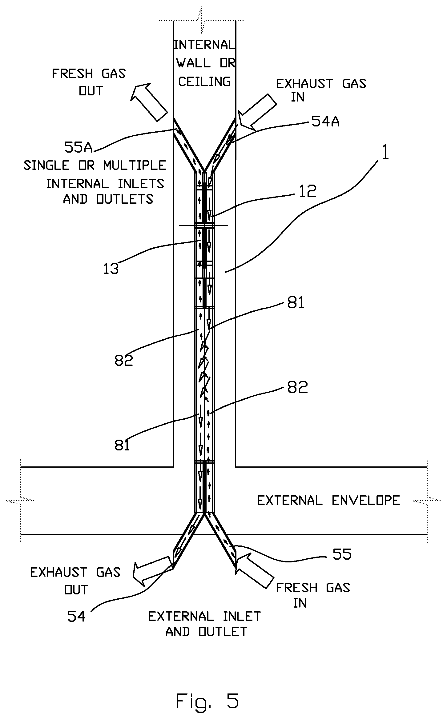
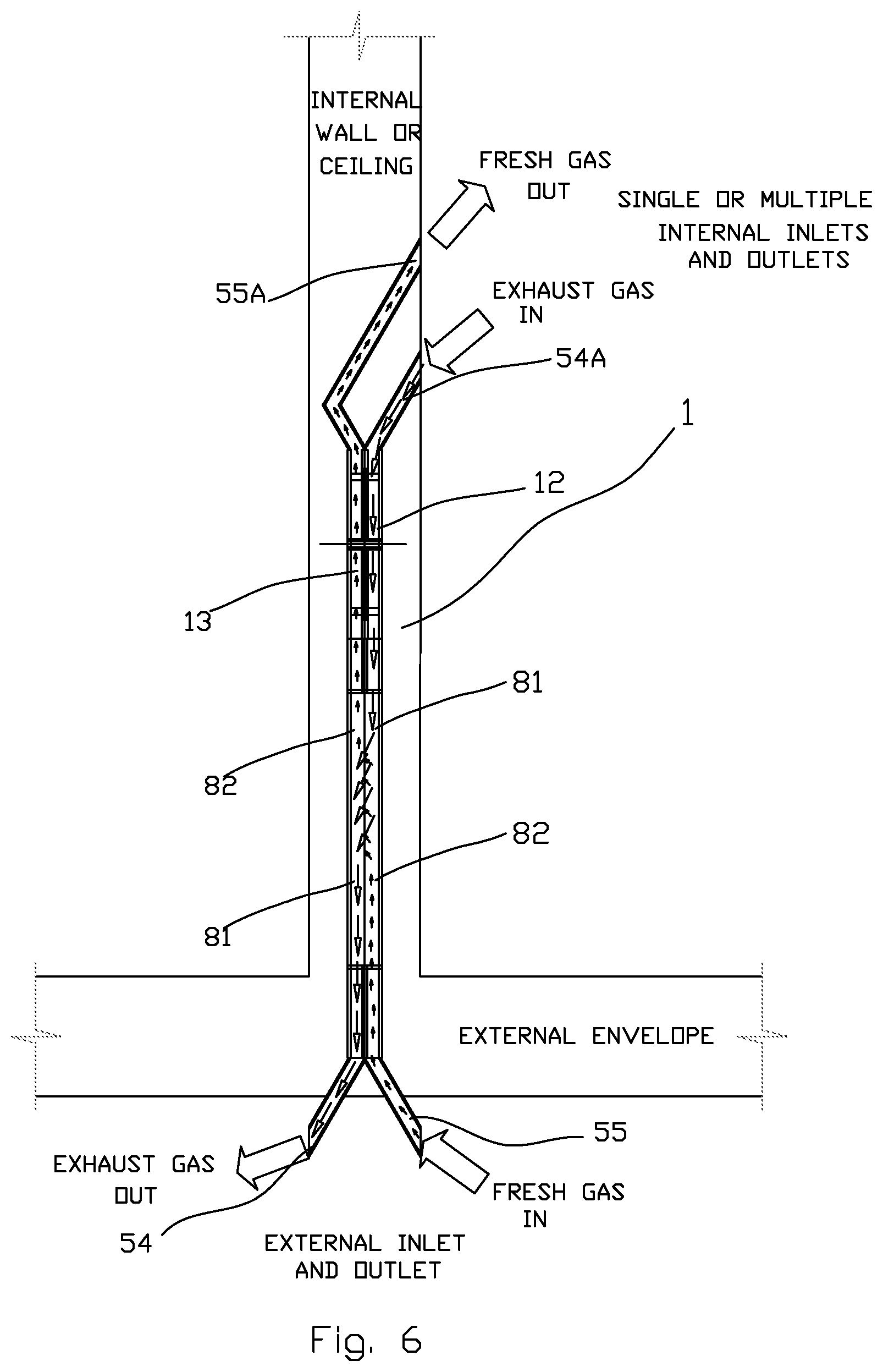
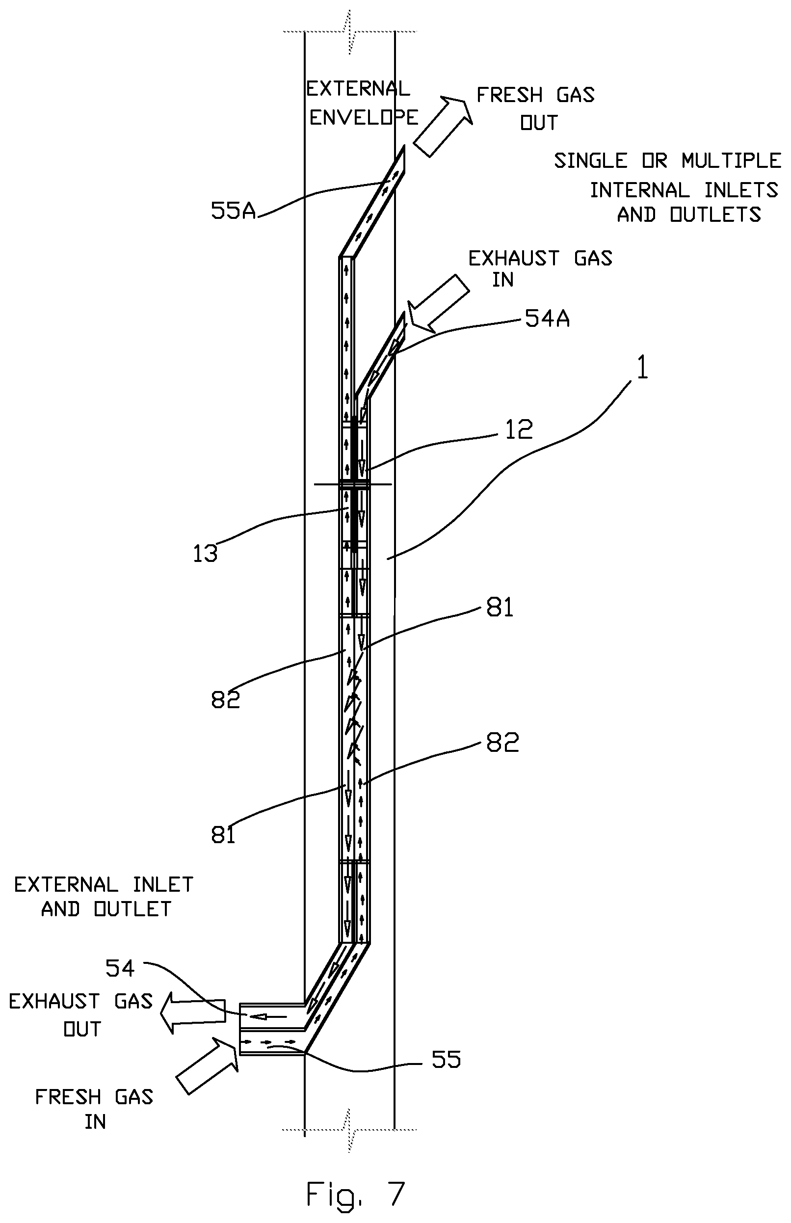
[0053] FIGS. 5-7 are schematic views showing options for mounting inside the wall or ceiling for the compact heat recovery ventilation system using changing side heat exchanger for the present invention.
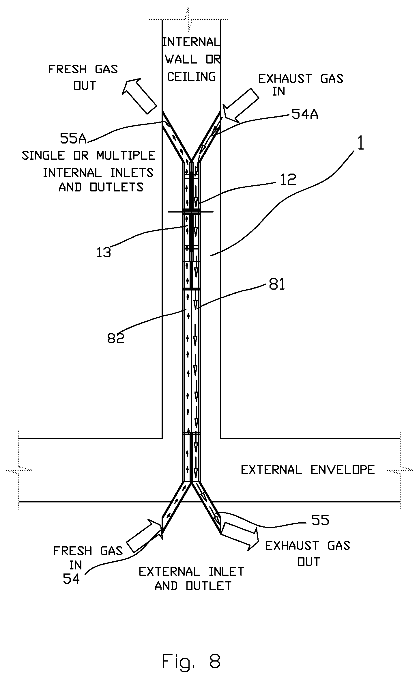
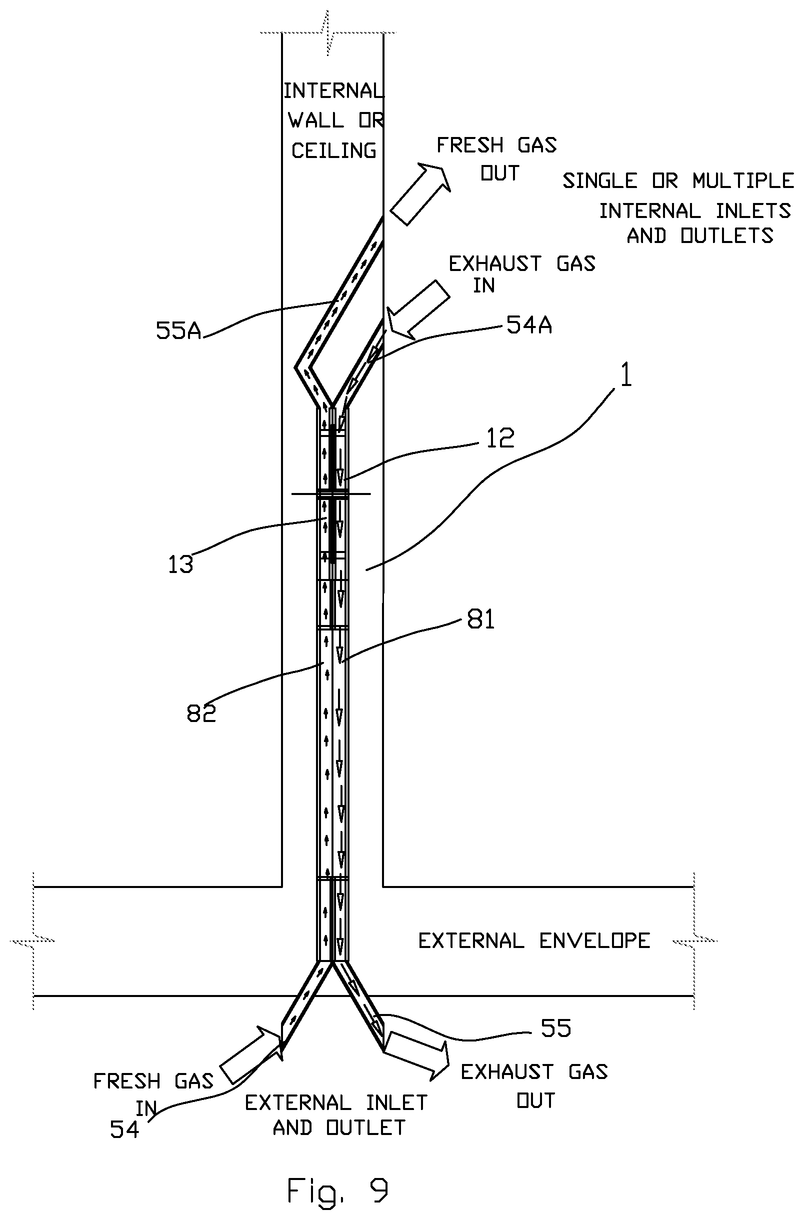
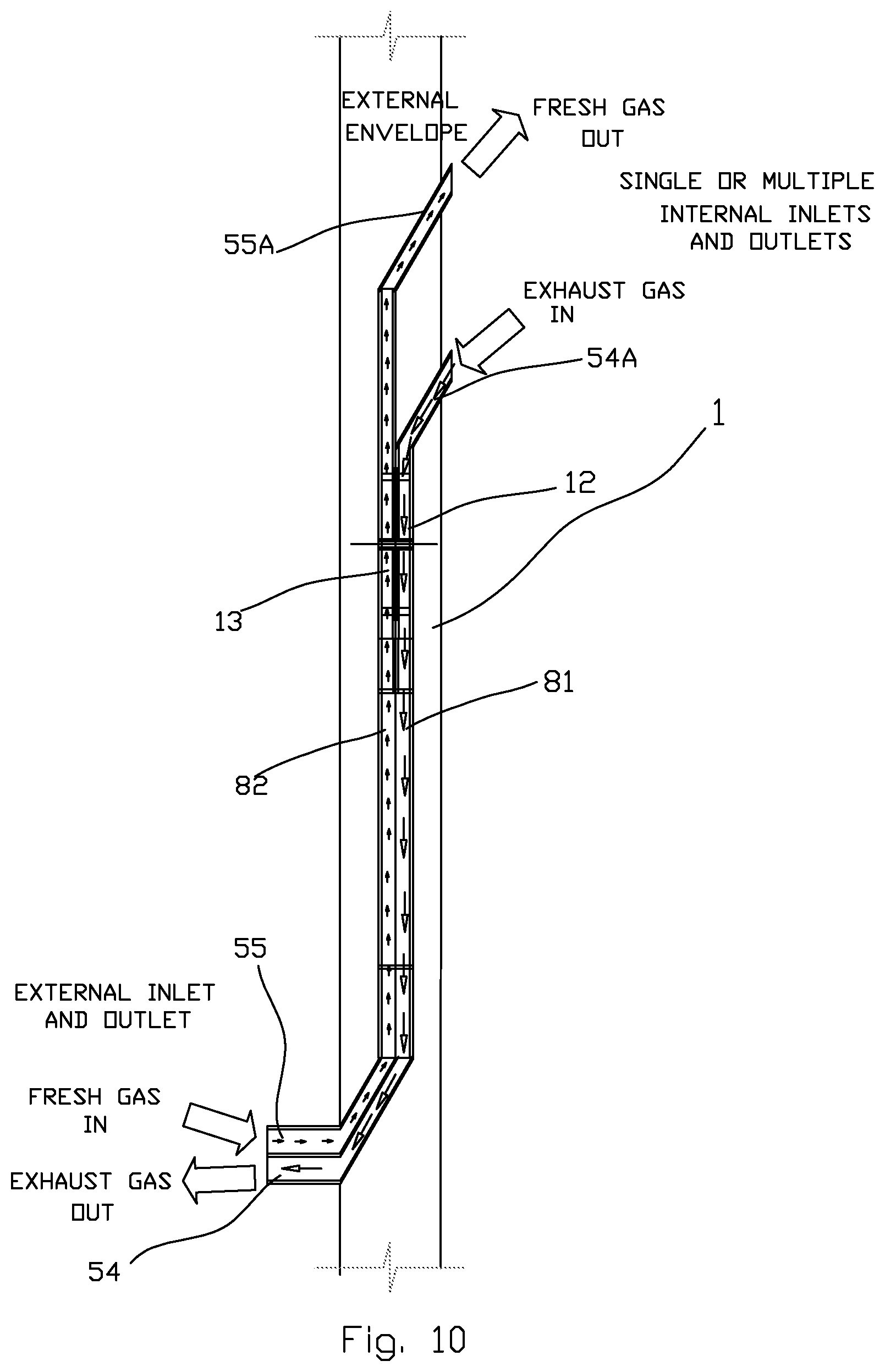
[0054] FIGS. 8-10 are schematic views showing options for mounting inside the wall or ceiling for the heat recovery system using traditional heat exchanger for the present invention
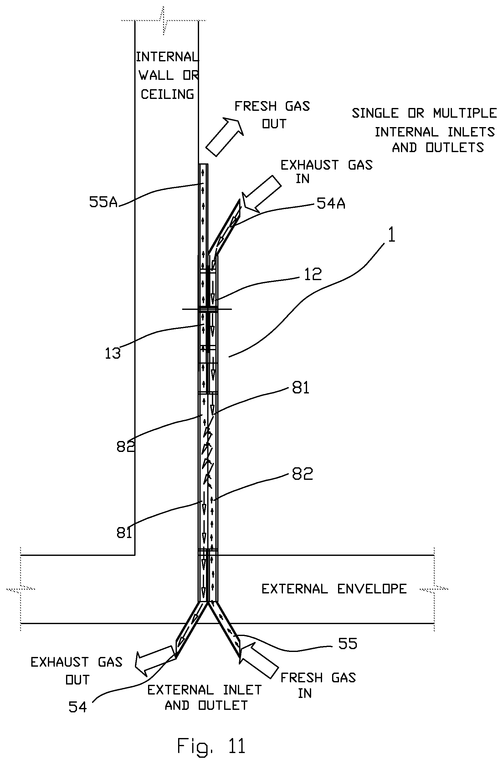
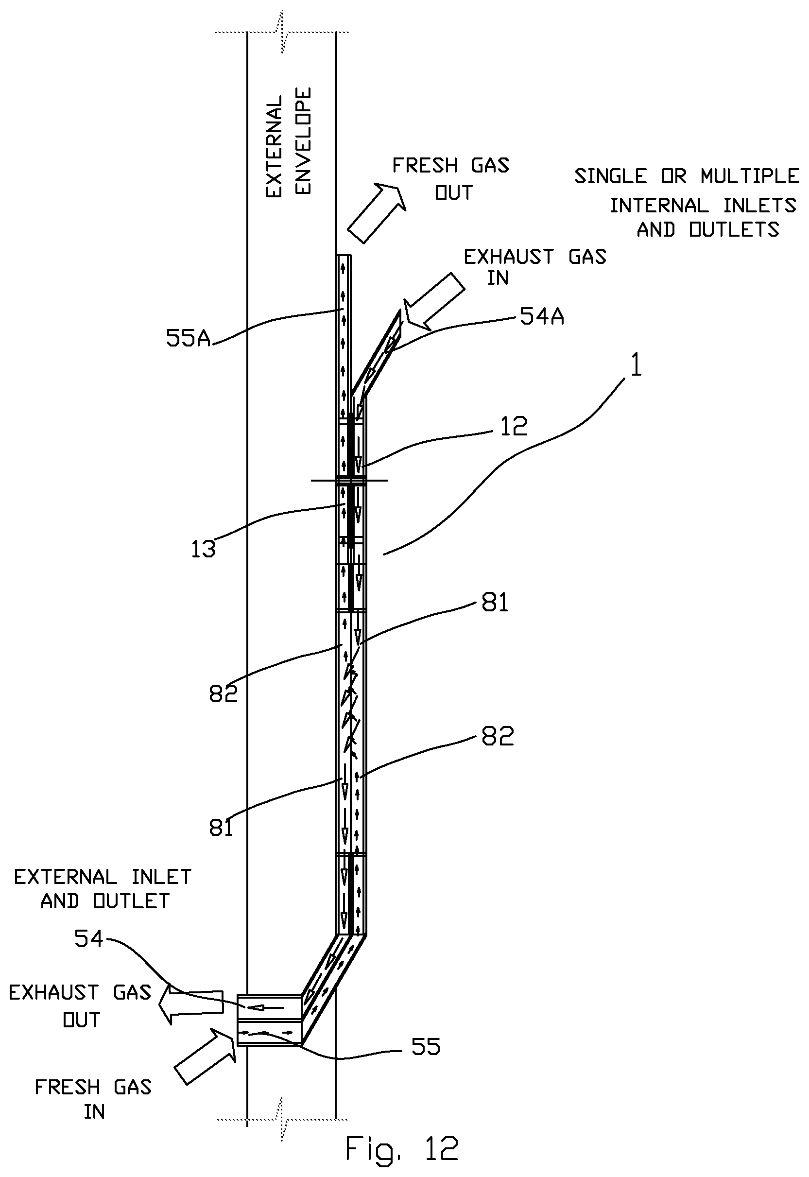
[0055] FIGS. 11-12 are schematic views showing options for mounting on the wall or ceiling for the compact heat recovery ventilation system using changing side heat exchanger for the present invention.
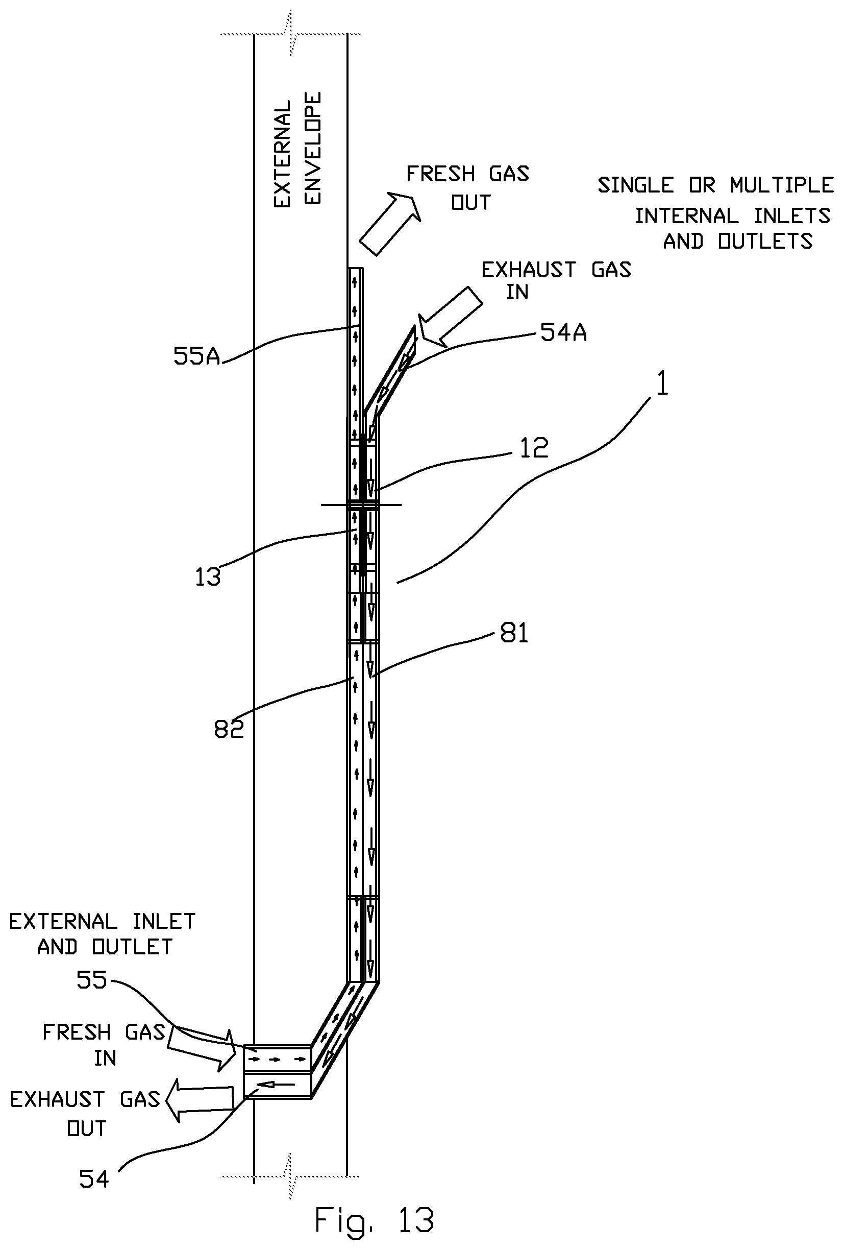
[0056] FIGS. 13-14 are schematic views showing options for mounting on the wall or ceiling for the compact heat recovery ventilation system using traditional heat exchanger for the present invention.
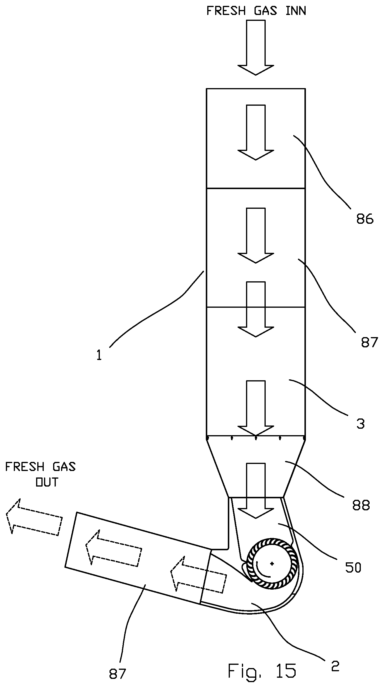
[0057] FIG. 15 Flat schematic view showing all connected in length components including blower, heat exchanger, filter, silencers with the exhaust gas duct.
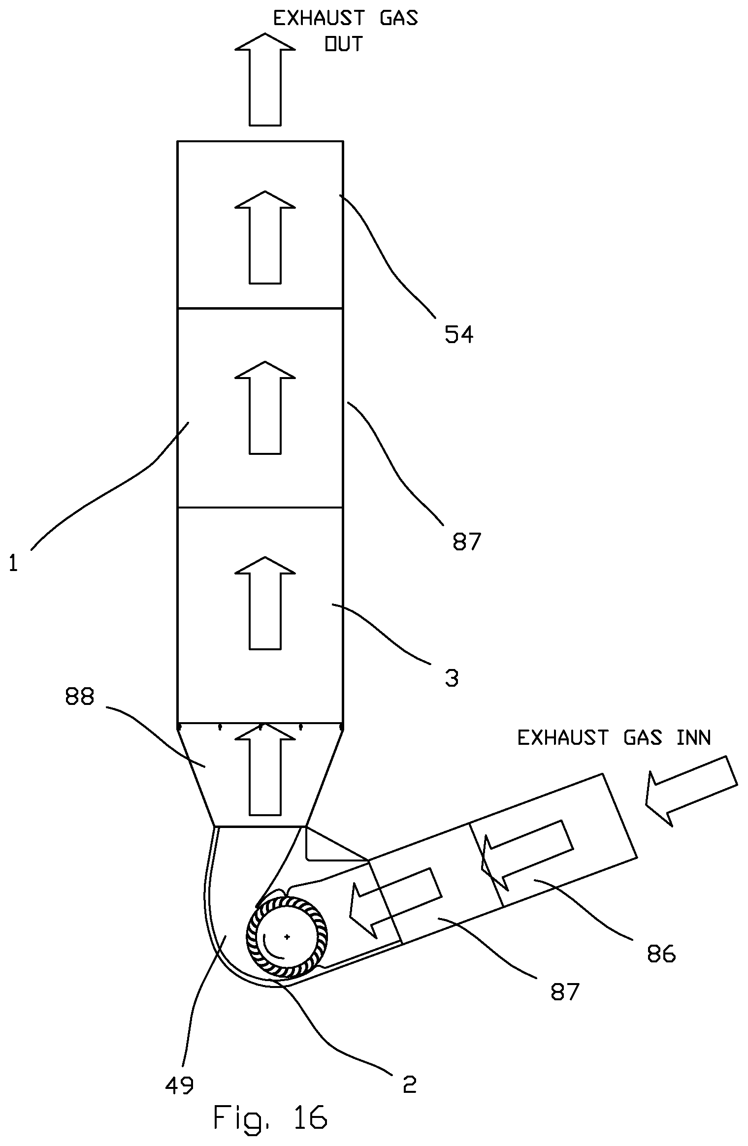
[0058] FIG. 16 Flat schematic view showing all connected in length components including blower, heat exchanger, filter, silencers with the fresh gas duct.
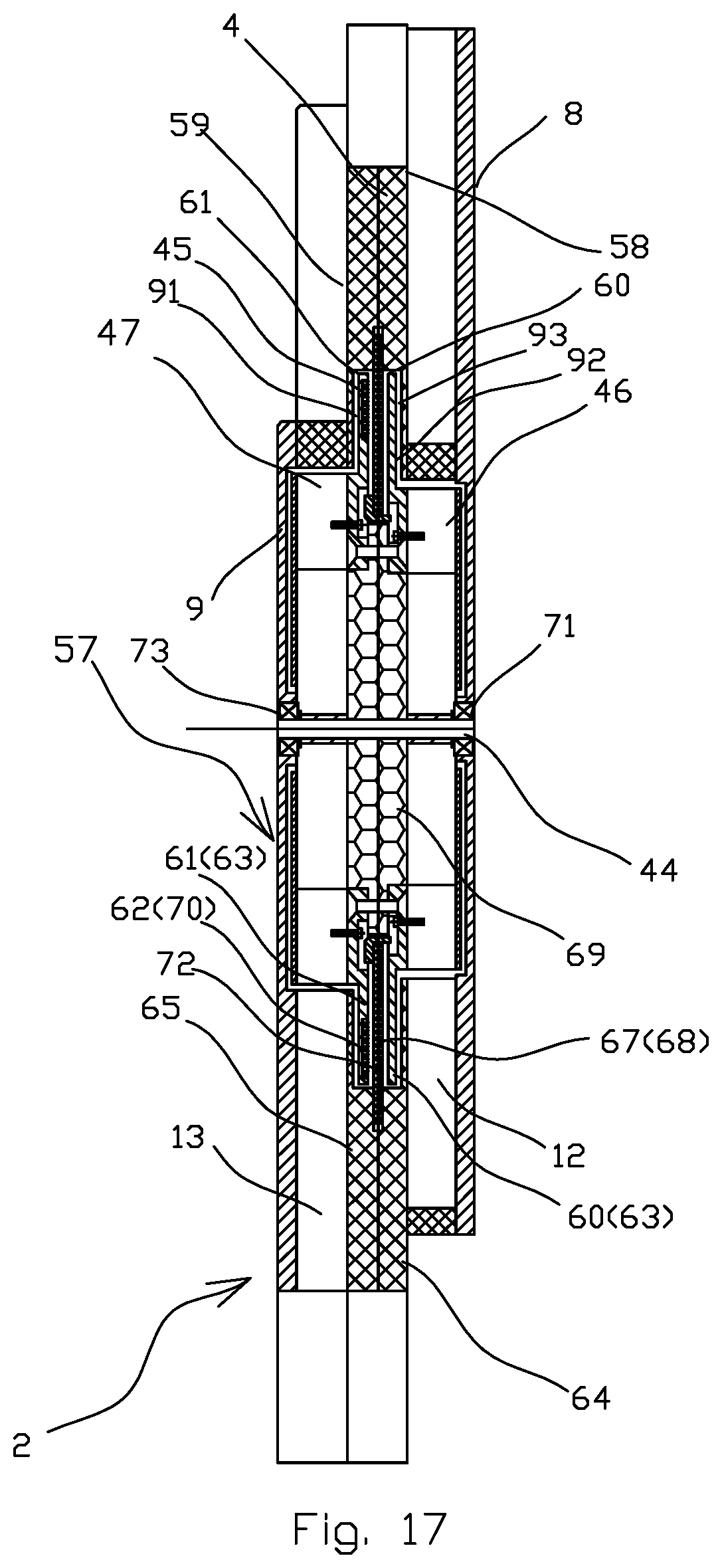
[0059] FIG. 17 is a cross section of the two blowers including integrated motor placed inside the housing.
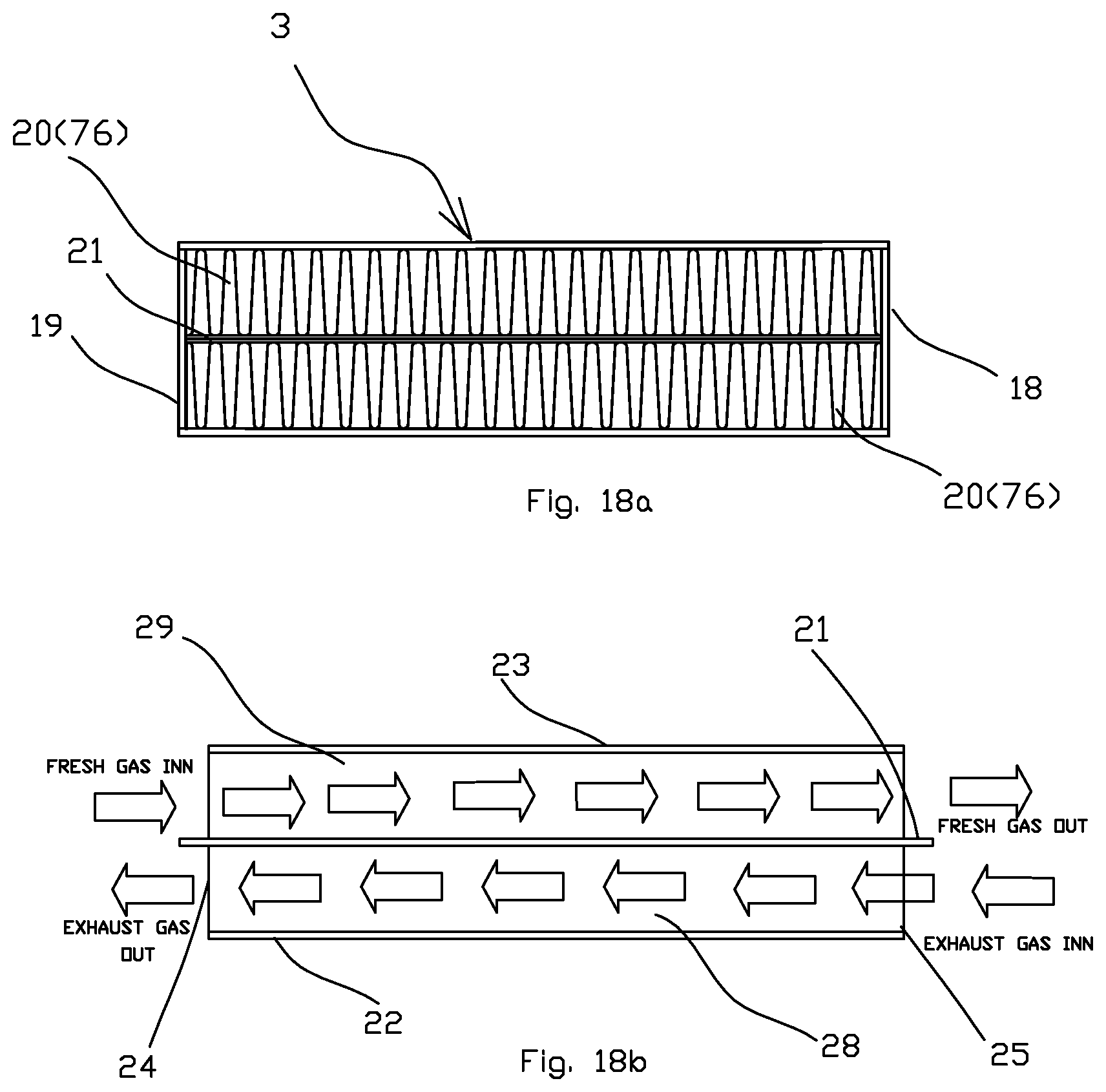
[0060] FIG. 18a is showing a traditional heat-exchanger view from the intake and outtake; FIG. 18b showing a traditional heat-exchanger cross-sectioned along the flow conduit.
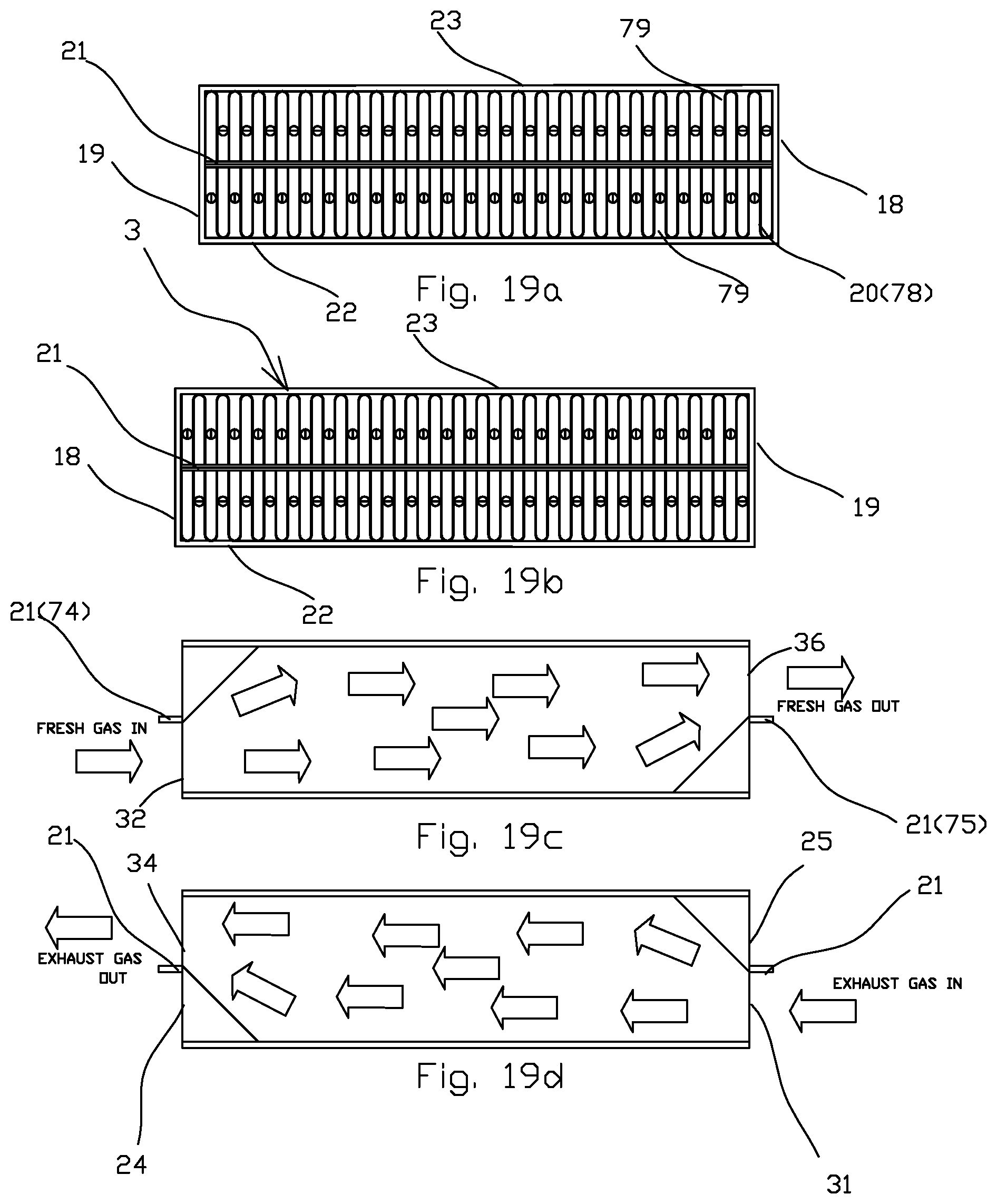
[0061] FIG. 19a is showing a changing flow sides corrugated fins heat-exchanger front view from one open end;
[0062] FIG. 19b the same heat-exchanger back view from the other open end.
[0063] FIG. 19c is showing cross-sectioned along one of the odd changing sides flow conduit.
[0064] FIG. 19d is showing cross-sectioned along one of the even changing sides flow conduit.
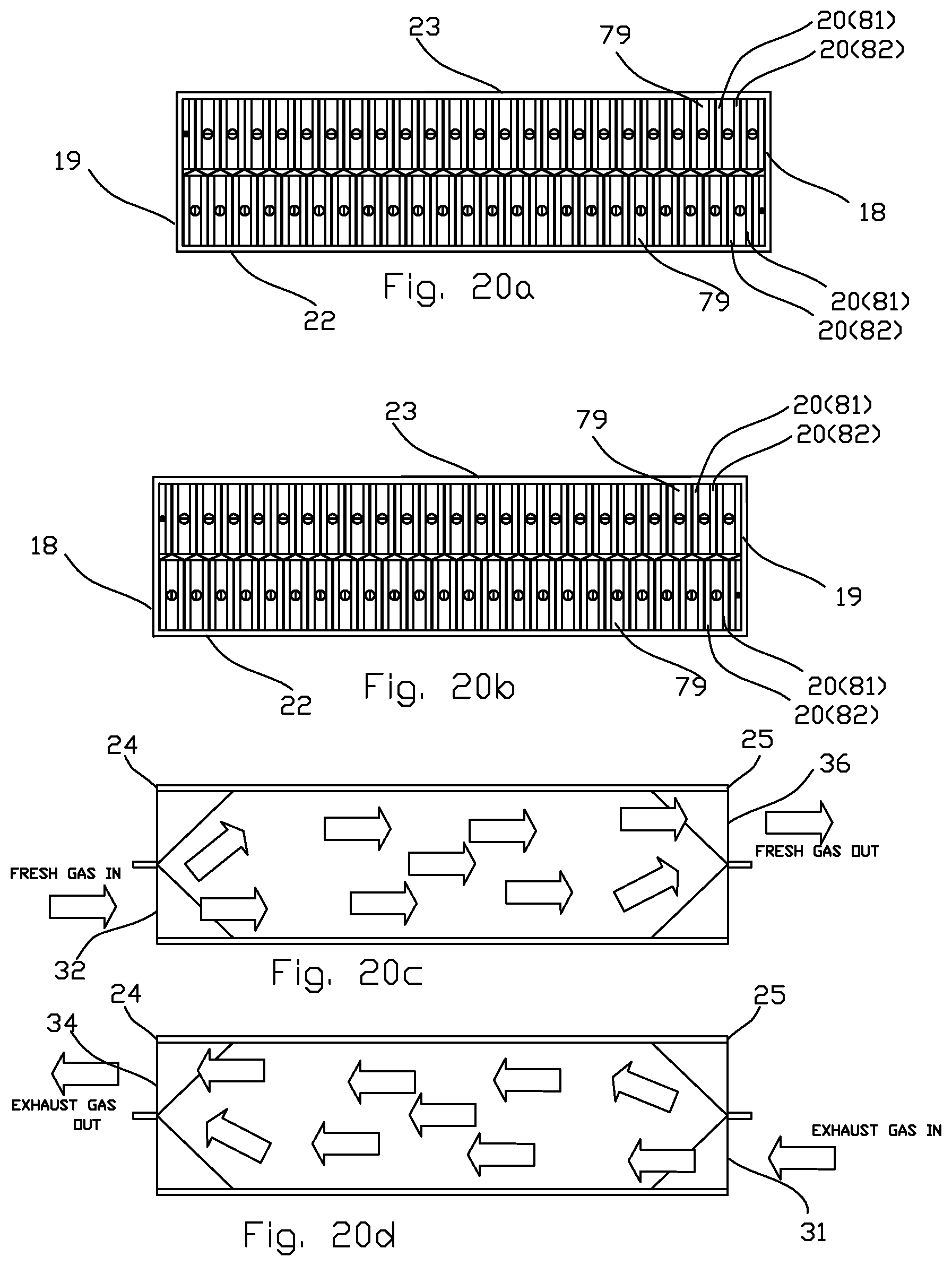
[0065] FIG. 20a is showing a changing flow sides plate fins heat-exchanger 3d section view from the open end (top outside panel is not shown).
[0066] FIG. 20b is showing cross-sectioned along one of the odd changing sides flow conduit.
[0067] FIG. 20c is showing cross-sectioned along one of the even changing sides flow conduit.
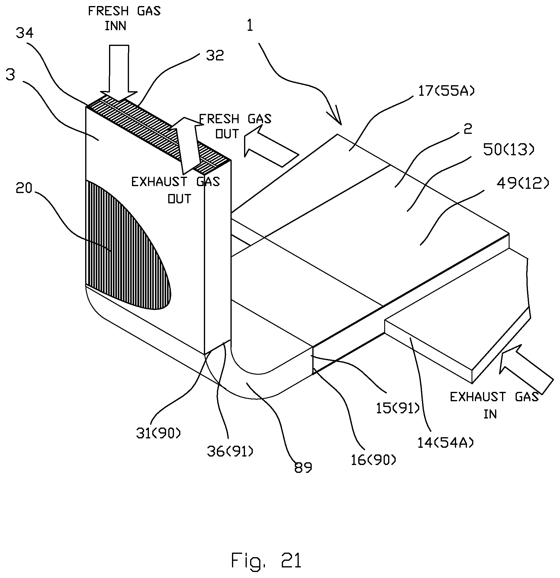
[0068] FIG. 21 is a perspective view showing the second embodiment of the current invention with L-shaped transition duct between heat exchanger and blowers.
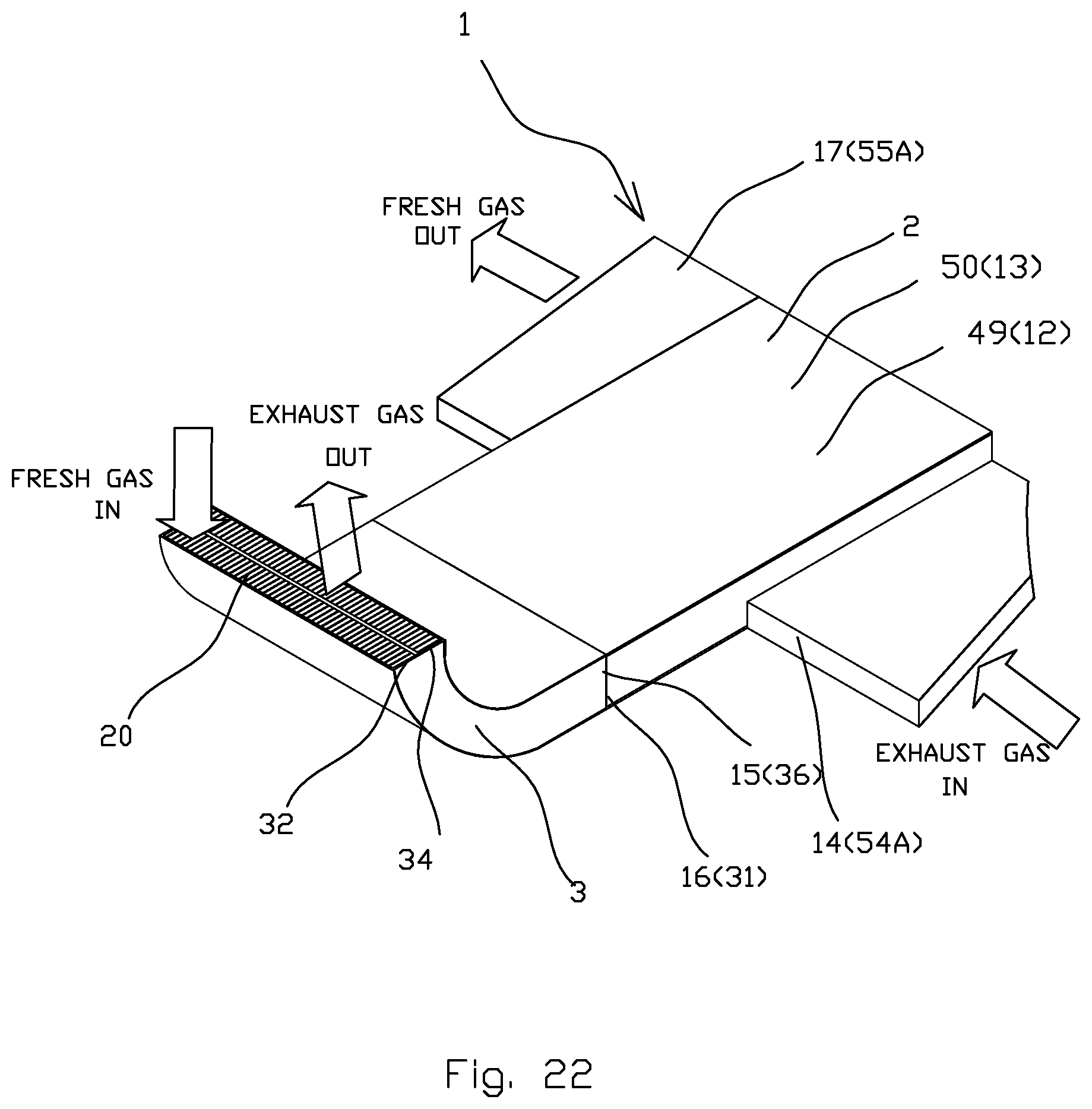
[0069] FIG. 22 is a perspective view showing the second embodiment of the current invention with L-shaped heat exchanger.
[0070] FIG. 23 is a perspective view showing the second embodiment of the current invention with 2 transition ducts between the heat exchanger assembly and air module assembly.
DETAILED DESCRIPTION OF PREFERRED EMBODIMENTS
[0071] Preferred embodiment of the present invention will be described in detail below with reference to the accompanying drawings.
[0072] A compact heat recovery system 1 (FIGS. 1-23) comprises air module assembly 2 and heat exchanger assembly 3. Air module assembly 2 includes base plate 4, two radial blowers 5 and 6 airflow guides 7, two side panels 8 and 9. The base plate 4 located between radial blower 5 and 6, divides the airflow in two hydraulically isolated canals, exhaust gas canal 12 and fresh gas canal 13 with exhaust gas inlet 14, fresh gas inlet 15 and exhaust gas outlet 16, fresh gas outlet 17.
[0073] The heat exchanger assembly 3 comprises of heat exchanging elements 20, center plate 21 fixed with outside panels 22 and 23 and withe with heat exchanger sides 18 and 19. The center plate 21 divides openings of the ends 24, 25 of the heat exchanger assembly 3 for two hydraulically isolated flow conduits 28 and 29 with exhaust gas intake 31, fresh gas intake 32 and exhaust gas outtake 34, fresh gas 36 outtake located at the ends 24, 25. The base plate 4, side panels 8, 9 of the air module assembly 2 connected respectively to the center plate 21, outside panels 22, 23 of the heat exchanger assembly 3.
[0074] The FIG. 1 shows the option of two blowers 5 and 6, one of them is a centrifugal blower 41 and the other is a cross flow blower 42. Both blowers 41 and 42 placed on the common shaft 44 and integrated with electric drive 45.
[0075] The FIG. 2 shows the option of two radial blowers 5 and 6, both of them made as crossflow blowers 49 and 50.
[0076] According to the (FIGS. 2-4) of the present invention both crossflow impellers 46 and 47 placed on the common shaft 44 and integrated with electric drive 45, rotate in one direction and operate as crossflow blowers 49, 50. Two airflow guides 51, 52 are outside the cross flow impellers 46, 47 and a guide vain 56 is located inside of each cross flow impeller 46, 47, therefore, exhaust gas flows through exhaust gas inlet duct 54A, exhaust gas inlet 53, cross flow blower 49, in exhaust gas canal 12, exhaust gas outlet 53A, exhaust gas intake 31 through heat exchanging elements 20 and exhaust gas outtake 34 of heat exchanger assembly 3 and exhaust gas outtake duct 54, while fresh gas flows through the fresh gas intake duct 55, fresh gas intake 32 through heat exchanging elements 20, fresh gas outtake 36 of the heat exchanger assembly 3, fresh gas inlet 15, cross flow blower 50 in fresh gas canal 13, and fresh gas outlet 17, fresh gas outlet duct 55A of air module assembly 2, thus providing countercurrent heat exchange process.
[0077] According to FIG. 17, the double radial impeller 57 comprises two radial impellers 46 and 47 that are respectively spaced between each side 58 and 59 of the base plate 4 and side panels 8 and 9, thus each of the radial impellers 46 and 47 located in each of the canal 12 and 13. Each of the radial impellers 46 and 47 attached to back plate disk 60 and 61 that are fixed to the hub 69 attached to shaft 44 based on bearings 71, 73 pressed in the side panels 8 and 9. One of the back plate disk 61 comprises magnetic elements 62, thus both of the back plate discs 60 and 61 form the rotor 63. Base plate 4 is divided in plane perpendicular to its thickness in two parts 64, 65 having between them a stator 67 that along with rotor 63 serves as the electric drive 45 of the air module assembly 2.
[0078] There are at least two design options for the electric drive 45. According to a first design option (FIG. 3), the stator 67 comprises of a circumferential arrayed coil windings 72 with magnetic axes coincided with a plane of the flat stator 67 and integrated with the base plate 4, while the magnetic elements 62 made as circumferential arrayed permanent magnets 70 placed and magnetized along the plane of the flat stator 68, thus magnetic axes of the coil windings 69 and the permanent magnets 70 located at one plane substantially. Such electric drive 45 is described in details in the U.S. Pat. No. 7,173,353 for the same Assignee.
[0079] According to a second design option (FIG. 17), the flat stator 68 comprises circumferential arrayed coil windings 72 with magnetic axes perpendicular to a plane of the flat stator 68 and integrated with the base plate 4, while the magnetic elements made 62 as circumferential arrayed permanent magnets 70 are magnetized perpendicular to the plane of the flat stator 68, thus magnetic axes of the coils windings 72 and the permanent magnets 70 of the rotor 63 are substantially parallel. Peripheral parts 60 and 61 of the rotor 63 placed inside of cylindrical cavities 91 and 92, creating a labyrinth 93 hydraulically isolating canals 12 and 13 of air module assembly 2.
[0080] All electrical coils made as printed overlapping coils on the PC board in accordance with the U.S. Pat. No. 7,623,013 that is incorporated in this application by reference.
[0081] FIG. 15 shows the fresh gas passage in a planar section of a compact heat recovery ventilation system 1, including air module assembly 2, heat exchanger assembly 3, fresh air filter assembly 86 and silencer assemblies 87. Fresh gas flows through filter assembly 86, silencer assembly 87, heat exchanger assembly 3, transition duct 88, crossflow blower 50 of air module assembly 2, and through a silencer assembly 87.
[0082] FIG. 16 shows the exhaust gas passage in a planar section of a compact heat recovery ventilation system 1, including air module assembly 2, heat exchanger assembly 3, fresh air filter assembly 86 and silencer assemblies 87. Exhaust gas flows through filter assembly 86, silencer assembly 87, crossflow blower 49 of air module assembly 2, transition duct 88, heat exchanger assembly 3, silencer assembly 87 and exhaust gas outtake duct 54.
[0083] FIG. 18a and FIG. 18b shown one of the options for heat exchanger assembly 3 with traditional heat exchange elements 20 made as a center plate 21 with protruded fins 76 from both sides of the center plate 21. As the center plate 21 forms separation between the two conduits 28, 29 along the length of the heat exchanger assembly 3. Exhaust gas is restricted to flow through conduit 28 from end 25 to end 24 along the side of the outside panel 22 thus exiting on the same outside panel side 22 as entered. Fresh gas is restricted to flow through conduit 29 from end 24 to end 25 along the side of the outside panel 23 thus exiting on the same outside panel side 23 as it entered.
[0084] FIGS. 19(a,b,c,d) show changeable gas flow side heat exchangers could be made as corrugated fins with a base plate divider or as plate heat exchanger based on the same principles FIGS. 20(a,b,c,d). The center plate 21 splits in two end center plates 74, 75 located respectively at the ends 24, 25 of the heat exchanger assembly 3 for both configurations.
[0085] Option shown in the FIG. 19 (a,b,c,d) includes the heat exchanger assembly 3 with heat exchanging elements 20 shaped as corrugated fins 78 made as a plurality of channels 79 divided by end center plate 74 and 75 located respectively at the ends 24, 25 of the heat exchanger assembly 3.
[0086] End 25 has exhaust gas intake 31 and fresh gas outtake, 36 while the end 24 has fresh gas intake 32 and exhaust gas outtake 34.
[0087] At the exhaust gas intake 31 at the end 24 every even channel 81 is sealed and every odd channel 82 is open, while at the fresh gas outtake 36 at the same end 24 every odd channel 82 is sealed and every even channel 81 is open.
[0088] For this particular heat exchanger with heat exchanging elements 20 at exhaust gas flows through the exhaust gas intake 31 next to outside panel 22 at end 24, through open odd channels 82 to the exhaust gas outtake 34 next to outside panel 23 at end 25, thus gas is forced to change sides.
[0089] Fresh gas flows through the fresh gas intake 32 next to outside panel 23 at end 25, through open even channels 81 out to the fresh gas outtake 36 next to outside panel 22 at end 24, thus gas is forced to change sides.
[0090] Option shown in the FIGS. 20(a,b,c,d) includes the heat exchanger assembly 3 with heat exchanging elements 20. The heat exchanging elements 20 are of plate type, where at both ends 24 and 25 at exhaust gas outtake 34 and exhaust gas intake 31 plurality of pairs of all odd plates 84 and even plates 83 are bended and sealed together.
[0091] At both ends 24 and 25 at fresh gas intake 32 and fresh gas outtake 36 pluralities of pairs of all even plates 83 and odd plates 84 are bended and sealed together.
[0092] At the end 24 of the heat exchanger assembly 3 the exhaust gas intake 31 is separated from fresh gas outtake 36 by center plate 74.
At the end 25 of the heat exchanger assembly 3 the fresh gas intake 32 is separated from exhaust gas outtake 34 by center plate 75.
[0093] For this particular heat exchanger assembly 3 with heat exchanging elements 20 the exhaust gas flows through the exhaust gas intake 31 next to outside panel 22 at end 24, through open odd channels 82 to the exhaust gas outtake 34 next to outside panel 23 at end 25, thus gas is forced to change sides.
[0094] Fresh gas flows through the fresh gas intake 32 next to outside panel 23 at end 25, through open even channels 81 out to the fresh gas outtake 36 next to outside panel 22 at end 24, thus gas is forced to change sides.
[0095] This gives additional flexibility in design as the air is free to move between opposite sides of the heat exchanger, and the air can exit on the other end of the heat exchanger on the opposite side than it entered.
[0096] The principals of such heat exchanger are described in U.S. Pat. No. DE4,301,296 "Plate heat exchange on countercurrent principle" and incorporated here by reference.
[0097] The heat exchangers described in FIGS. 19 and 20 are the most beneficial for our proposed application. The heat transfer distance is much shorter, and therefore, the heat exchanger efficiency relies in much lesser degree on heat conductance coefficient of the heat exchanger material. The heat exchanger can therefore be made out of plastic material. By using a vapor permeable material in the heat exchanger folded fins or plate, humidity can be recovered. Thus, upgrading the heat recovery system to an energy recovery system.
[0098] The changing or sides of the airflow inside the heat exchanger, is also beneficial as it can be used to prevent formation of dead pockets inside the heat exchanger which may accumulate and condensate dirt, hence, having both outlets on the bottom side can help reduce any such accumulation inside the heat exchanger.
[0099] There are several alignments of heat exchangers assembly 3 and air module assembly 2 that are possible in the compact heat recovery ventilation system 1.
[0100] FIGS. 21, 22 and 23 show three different alignments of the compact heat recovery ventilation system 1. FIG. 21 shows L-shaped transition 89 where heat exchanger outside panels 22,23 and center plate 21 no longer connect directly with the air module assembly 2, and are no longer parallel with side panels 8,9 or base plate 4 of the air module assembly 2. FIG. 22 shows a configuration where the compact heat recovery ventilation system 1 has a bent exchanger assembly 3. FIG. 23 shows configuration where the compact heat recovery ventilation assembly 1, has two separate transition ducts connecting heat exchanger assembly 3 to the air module assembly 2.
[0101] According to FIG. 21 of the present invention the air module assembly 2 is connected to the heat exchanger assembly 3 with transition ducts. The exhaust gas flows through the exhaust gas duct inlet duct 54A, exhaust gas inlet 14, crossflow blower 49 in the exhaust gas canal 12 of the air module assembly 2, the exhaust gas outlet 53A, the exhaust transition channel 90 of the L shaped transition 89, exhaust gas intake 31 through heat exchanging elements 20 and exhaust gas outtake 34 of heat exchanger assembly 3, while fresh gas flows through the fresh gas intake 32 through heat exchanging elements 20, fresh gas outtake 36 of the heat exchanger assembly 3, fresh air transition channel 91 of the transition 89, fresh gas inlet 15, cross flow blower 50 in fresh gas canal 13, and fresh gas outlet 17, fresh gas outlet duct 55A of air module assembly 2, thus providing countercurrent heat exchange process.
[0102] According to FIG. 22 of the present invention the air module assembly 2 is connected to the heat exchanger assembly 3 which is L-shaped. The exhaust gas flows through the exhaust gas inlet duct 54A, exhaust gas inlet 14, crossflow blower 49 in the exhaust gas canal 12 of the air module assembly 2, the exhaust gas outlet 16, exhaust gas intake 31 through heat exchanging elements 20 and exhaust gas outtake 34 of the L shaped heat exchanger assembly 3, while fresh gas flows through the fresh gas intake 32 through heat exchanging elements 20, fresh gas outtake 36 of the L-shaped heat exchanger assembly 3, fresh gas inlet 15, cross flow blower 50 in fresh gas canal 13, and fresh gas outlet 17, fresh gas outlet duct 55A of air module assembly 2, thus providing countercurrent heat exchange process.
[0103] According to FIG. 23 of the present invention the air module assembly 2 is connected to the heat exchanger assembly 3 with transition duct assembly 94. The exhaust gas flows through the exhaust gas inlet duct 54A, exhaust gas inlet 14, crossflow blower 49 in the exhaust gas canal 12 of the air module assembly 2, the exhaust gas outlet 16, exhaust gas transition duct 95, exhaust gas intake 31 through heat exchanging elements 20 and exhaust gas outtake 34 of heat exchanger assembly 3, while fresh gas flows through the fresh gas intake 32 through heat exchanging elements 20, fresh gas outtake 36 of the heat exchanger assembly 3, fresh gas transition duct 96, fresh gas inlet 15, cross flow blower 50 in fresh gas canal 13, and fresh gas outlet 17, fresh gas outlet duct 55A of air module assembly 2, thus providing countercurrent heat exchange process.
[0104] The compact heat recovery ventilation system 1 operates in the following way. When an electric power is supplied to the flat stator 68 of the electric drive 45, the alternative electromagnetic field is created. This electromagnetic field is controlled by the electronic controllers (not shown on Figs.) and interacts with a magnetic field created by the magnetic rotor 63. As a result of this interaction, the magnetized rotor 63 causes the double radial impeller 57 to rotate. The exhaust gas flows through the exhaust gas inlet duct 54A, crossflow blower 49 in the exhaust gas canal 12 of the air module assembly 2, the exhaust gas outlet 53A, exhaust gas intake 31 through heat exchanging elements 20 and exhaust gas outtake 34 of heat exchanger assembly 3 and exhaust gas outtake duct 54, while fresh gas flows through the fresh gas intake duct 55, fresh gas intake 32 through heat exchanging elements 20, fresh gas outtake 36 of the heat exchanger assembly 3, flexible fresh air transition channel 91 of the transition 89, fresh gas inlet 15, cross flow blower 50 in fresh gas canal 13, and fresh gas outlet 17, fresh gas outlet duct 55A of air module assembly 2, thus providing countercurrent heat exchange process.
[0105] According to the present invention, the compact heat recovery ventilation system 1 due to the mutual arrangement of the hydraulic schemes of the crossflow blowers 42 with the double side radial impeller 75 parallel to the base plate 4 of the air module assembly 2, provides a thin, compact, highly efficient, simple, reliable and less expensive device that can easily be mounted inside the wall, ceiling or inside a vehicle.
[0106] These combination of the dual thin blowers with the integrated single motor between them, mounted with the side changeable heat exchanger including additional modules such as filters, silencers, humidifiers, assembled in a flat modular way, allows to create a flat compact heat recovery system capable of being soundless, wall-mounted or even be able to fit inside of the wall or ceiling.
[0107] While the invention has been described with reference to various embodiments, it should be understood that these embodiments are only illustrative and that the scope of the invention is not limited to just those. Many variations, modifications and improvements of the embodiments described are possible. Variations and modifications of the embodiments disclosed herein may be made based on description set forth herein, without departing from the scope and spirit of the invention as set forth in the following claims.
In accordance to the above description of proposed invention first prototype of such system was manufactured, installed in the standard wall and successfully tested.
* * * * *
D00000
D00001
D00002
D00003
D00004
D00005
D00006
D00007
D00008
D00009
D00010
D00011
D00012
D00013
D00014

D00015
D00016
D00017
D00018
D00019
D00020
D00021
D00022
D00023

XML
uspto.report is an independent third-party trademark research tool that is not affiliated, endorsed, or sponsored by the United States Patent and Trademark Office (USPTO) or any other governmental organization. The information provided by uspto.report is based on publicly available data at the time of writing and is intended for informational purposes only.
While we strive to provide accurate and up-to-date information, we do not guarantee the accuracy, completeness, reliability, or suitability of the information displayed on this site. The use of this site is at your own risk. Any reliance you place on such information is therefore strictly at your own risk.
All official trademark data, including owner information, should be verified by visiting the official USPTO website at www.uspto.gov. This site is not intended to replace professional legal advice and should not be used as a substitute for consulting with a legal professional who is knowledgeable about trademark law.