Gear Drive Mechanisms For Surgical Instruments
Baril; Jacob C.
U.S. patent application number 16/817928 was filed with the patent office on 2020-09-24 for gear drive mechanisms for surgical instruments. The applicant listed for this patent is Covidien LP. Invention is credited to Jacob C. Baril.
| Application Number | 20200300341 16/817928 |
| Document ID | / |
| Family ID | 1000004750795 |
| Filed Date | 2020-09-24 |


| United States Patent Application | 20200300341 |
| Kind Code | A1 |
| Baril; Jacob C. | September 24, 2020 |
GEAR DRIVE MECHANISMS FOR SURGICAL INSTRUMENTS
Abstract
A surgical instrument includes a handle assembly having a gear drive mechanism. The gear drive mechanism includes a variable radius gear to provide a desired mechanical advantage to a user during actuation of a movable handle of the surgical instrument.
| Inventors: | Baril; Jacob C.; (Norwalk, CT) | ||||||||||
| Applicant: |
|
||||||||||
|---|---|---|---|---|---|---|---|---|---|---|---|
| Family ID: | 1000004750795 | ||||||||||
| Appl. No.: | 16/817928 | ||||||||||
| Filed: | March 13, 2020 |
Related U.S. Patent Documents
| Application Number | Filing Date | Patent Number | ||
|---|---|---|---|---|
| 62820487 | Mar 19, 2019 | |||
| Current U.S. Class: | 1/1 |
| Current CPC Class: | B25G 1/002 20130101; F16H 19/04 20130101; F16H 3/42 20130101; F16H 1/20 20130101 |
| International Class: | F16H 3/42 20060101 F16H003/42; F16H 1/20 20060101 F16H001/20; F16H 19/04 20060101 F16H019/04; B25G 1/00 20060101 B25G001/00 |
Claims
1. A surgical instrument, comprising: a handle assembly including a housing and a movable handle pivotally connected to the housing; an elongated shaft extending distally from the handle assembly and defining a longitudinal axis; a drive member extending at least partially through the elongated shaft and movable along the longitudinal axis relative to the elongated shaft; and a drive gear mechanism disposed at least partially within the housing, the drive gear mechanism including a first gear disposed in mechanical cooperation with the movable handle, a second gear disposed in mechanical cooperation with the first gear, a third gear disposed in mechanical cooperation with the second gear, and a fourth gear disposed in mechanical cooperation with the third gear and with the drive member, the third gear defining more than one radius.
2. The surgical instrument according to claim 1, wherein the third gear defines a first radius and a second radius, the first radius of the third gear being the same as a radius of the second gear.
3. The surgical instrument according to claim 2, wherein the second radius of the third gear is the same as a radius of the fourth gear.
4. The surgical instrument according to claim 1, wherein a first radius of the third gear is from about 0.17 inches to about 0.55 inches, and a second radius of the third gear is from about 0.75 inches to about 1.25 inches.
5. The surgical instrument according to claim 1, wherein a first radius of the third gear is about 0.375 inches, and a second radius of the third gear is about 1.0 inches.
6. The surgical instrument according to claim 1, wherein the first gear is formed on the movable handle.
7. The surgical instrument according to claim 1, wherein the fourth gear is formed on the drive member.
8. A drive gear mechanism for use with a surgical instrument, the drive gear mechanism comprising: a first gear defining a radius and including a plurality of teeth; a second gear defining a radius and including a plurality of teeth, the plurality of teeth of the second gear configured to engage the plurality of teeth of the first gear; a third gear including a first portion defining a first radius, a second portion defining a second radius that is different from the first radius, and a plurality of teeth, the plurality of teeth of the first portion of the third gear configured to engage the plurality of teeth of the second gear; and a fourth gear including a plurality of teeth and disposed in mechanical cooperation with a drive member of the surgical instrument, the plurality of teeth of the fourth gear configured to engage the plurality of teeth of the second portion of the third gear.
9. The drive gear mechanism according to claim 8, wherein the first radius of the third gear is the same as a radius of the second gear.
10. The drive gear mechanism according to claim 9, wherein the second radius of the third gear is the same as a radius of the fourth gear.
11. The drive gear mechanism according to claim 8, wherein the first radius of the third gear is from about 0.17 inches to about 0.55 inches, and the second radius of the third gear is from about 0.75 inches to about 1.25 inches.
12. The drive gear mechanism according to claim 8, wherein the first radius of the third gear is about 0.375 inches, and the second radius of the third gear is about 1.0 inches.
13. A handheld and actuatable surgical instrument, comprising: a housing pivotally supporting a movable handle; an elongated shaft extending from the housing and being configured to support a surgical tool assembly for performing a surgical function; a drive member extending at least partially through the elongated shaft and movable along a longitudinal axis of the elongated shaft; and a drive gear mechanism disposed at least partially within the housing, the drive gear mechanism including a gear train including a plurality of gears, wherein at least one gear of the plurality of gears defines more than one radius.
14. The surgical instrument according to claim 13, wherein the gear train of the drive gear mechanism includes: a first gear disposed in mechanical cooperation with the movable handle; a second gear disposed in mechanical cooperation with the first gear; a third gear disposed in mechanical cooperation with the second gear; and a fourth gear disposed in mechanical cooperation with the third gear and with the drive member, the third gear defining more than one radius.
15. The surgical instrument according to claim 14, wherein the third gear defines a first radius and a second radius, the first radius of the third gear being the same as a radius of the second gear.
16. The surgical instrument according to claim 15, wherein the second radius of the third gear is the same as a radius of the fourth gear.
17. The surgical instrument according to claim 14, wherein a first radius of the third gear is from about 0.17 inches to about 0.55 inches, and a second radius of the third gear is from about 0.75 inches to about 1.25 inches.
18. The surgical instrument according to claim 14, wherein a first radius of the third gear is about 0.375 inches, and a second radius of the third gear is about 1.0 inches.
19. The surgical instrument according to claim 14, wherein the first gear is formed on the movable handle.
20. The surgical instrument according to claim 14, wherein the fourth gear is formed on the drive member.
Description
CROSS-REFERENCE TO RELATED APPLICATION
[0001] The present application claims the benefit of and priority to U.S. Provisional Patent Application Ser. No. 62/820,487, filed on Mar. 19, 2019, the entire content of which is incorporated herein by reference.
BACKGROUND
Technical Field
[0002] This disclosure relates to gear drive mechanisms for surgical instruments. More particularly, the disclosure relates to gear drive mechanisms having a variable gear for use with handle assemblies of surgical instruments.
Description of Related Art
[0003] Several types of surgical instruments include a handle assembly that relies on mechanical action between a movable handle and a stationary handle to provide the forces necessary to perform the desired functions of the surgical instrument. Additionally, many surgical instruments utilize a single movable handle to provide multiple functions.
[0004] Generally, such movable handles used on surgical instruments are one of two types. One type is a simple pivoted handle that provides a near constant mechanical advantage throughout its stroke, and which is useful in many surgical situations. The second type of handle includes an additional link to provide a geometrically increasing mechanical advantage toward the end of its stroke to help provide a larger force, which may be desired to compress tissue or to deploy a surgical clip into tissue, for example.
[0005] However, many surgical instruments have different mechanical advantage requirements based on the functions a particular surgical instrument provides, where a constant mechanical advantage or a geometrically increasing mechanical advantage may not be the ideal solution.
SUMMARY
[0006] The disclosure relates to a surgical instrument including a handle assembly, an elongated shaft, a drive member, and a drive gear mechanism. The handle assembly includes a housing and a movable handle pivotally connected to the housing. The elongated shaft extends distally from the handle assembly and defines a longitudinal axis. The drive member extends at least partially through the elongated shaft and is movable along the longitudinal axis relative to the elongated shaft. The drive gear mechanism is disposed at least partially within the housing, and includes a first gear disposed in mechanical cooperation with the movable handle, a second gear disposed in mechanical cooperation with the first gear, a third gear disposed in mechanical cooperation with the second gear, and a fourth gear disposed in mechanical cooperation with the third gear and with the drive member. The third gear defines more than one radius.
[0007] In embodiments, the third gear defines a first radius and a second radius, where the first radius of the third gear is the same as a radius of the second gear. It is also disclosed that the second radius of the third gear is the same as a radius of the fourth gear.
[0008] It is further disclosed that a first radius of the third gear is from about 0.17 inches to about 0.55 inches (e.g., about 0.375 inches), and a second radius of the third gear is from about 0.75 inches to about 1.25 inches (e.g., about 1.0 inches).
[0009] In disclosed embodiments, the first gear is formed on the movable handle and the fourth gear is formed on the drive member.
[0010] The present disclosure also relates to a drive gear mechanism for use with a surgical instrument, including a first gear, a second gear, a third gear, and a fourth gear. The first gear defines a radius and includes a plurality of teeth. The second gear defines a radius and includes a plurality of teeth configured to engage the plurality of teeth of the first gear. The third gear includes a first portion defining a first radius, a second portion defining a second radius that is different from the first radius, and a plurality of teeth. The plurality of teeth of the first portion of the third gear is configured to engage the plurality of teeth of the second gear. The fourth gear includes a plurality of teeth and is disposed in mechanical cooperation with a drive member of the surgical instrument. The plurality of teeth of the fourth gear is configured to engage the plurality of teeth of the second portion of the third gear.
[0011] In embodiments, the first radius of the third gear is the same as a radius of the second gear. It is also disclosed that the second radius of the third gear is the same as a radius of the fourth gear.
[0012] It is further disclosed that the first radius of the third gear is from about 0.17 inches to about 0.55 inches (e.g., about 0.375 inches), and the second radius of the third gear is from about 0.75 inches to about 1.25 inches (e.g., about 1.0 inches).
BRIEF DESCRIPTION OF THE DRAWINGS
[0013] Embodiments of gear drive mechanisms for surgical instruments are disclosed herein with reference to the drawings wherein:
[0014] FIG. 1 is a perspective view of a handle assembly of a surgical instrument in accordance with an embodiment of the disclosure; and
[0015] FIGS. 2-4 are cross-sectional views of the handle assembly of FIG. 1, as taken through 2-2 of FIG. 1, illustrating a gear drive mechanism of the surgical instrument in various positions.
DETAILED DESCRIPTION OF EMBODIMENTS
[0016] Embodiments of gear drive mechanisms, in accordance with the disclosure, will now be described in detail with reference to the figures wherein like reference numerals identify similar or identical structural elements. As shown in the drawings and described throughout the following description, as is traditional when referring to relative positioning on a surgical instrument, the term "proximal" refers to the end of the apparatus which is closer to the user and the term "distal" refers to the end of the apparatus which is farther away from the user.
[0017] With initial reference to FIG. 1, a surgical instrument is shown and is generally designated as reference number 10. Surgical instrument 10 generally includes a handle assembly 100, and an elongated assembly 200 defining a longitudinal axis "A-A" and extending distally from handle assembly 100. Handle assembly 100 includes a housing 110, a movable (e.g., pivotable) handle 120, and a stationary handle 130. An end effector, which is not explicitly shown in the accompanying figures, is coupled to a distal end of elongated assembly 200. As the gear drive mechanisms described herein are usable with various types of surgical instruments having various types of end effectors, particular end effectors are not shown.
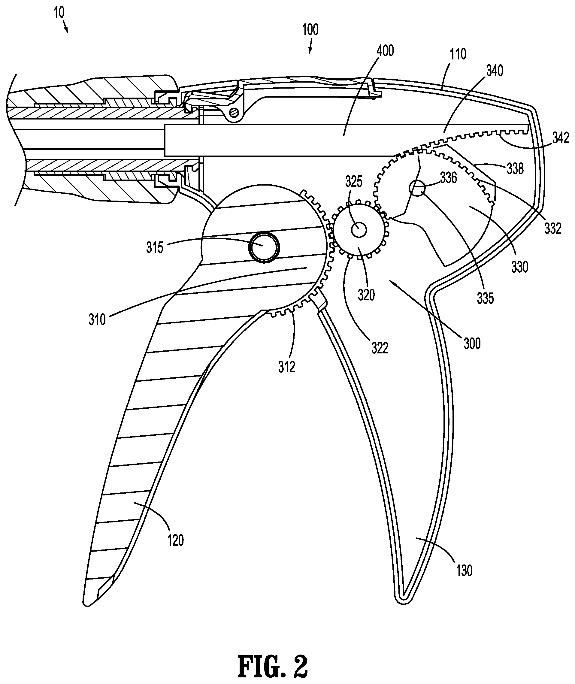
[0018] Referring now to FIGS. 2-4, internal portions of handle assembly 100 are shown including a drive gear mechanism 300 and a drive member 400. Drive gear mechanism 300 includes a first gear 310, a second gear 320, a third gear or shell or nautilus gear 330, and a fourth gear 340. First gear 310 includes a plurality of teeth 312 and is associated with or forms part of movable handle 120. Movable handle 120, and thus first gear 310, is pivotable or rotatable relative to housing 110 of handle assembly 100 about a first structure or pin 315. Second gear 320 includes a plurality of teeth 322, is disposed within housing 110 of handle assembly 100, and is rotatable relative to housing 110 of handle assembly 100 about a second structure, hub or pin 325. Teeth 322 of second gear 320 are configured to engage and mesh with teeth 312 of first gear 310. Third gear 330 includes a plurality of teeth 332, is disposed within housing 110 of handle assembly 100, and is rotatable relative to housing 110 of handle assembly 100 about a third structure, hub or pin 335. Fourth gear 340 includes a plurality of teeth 342 and is associated with or forms part of drive member 400.
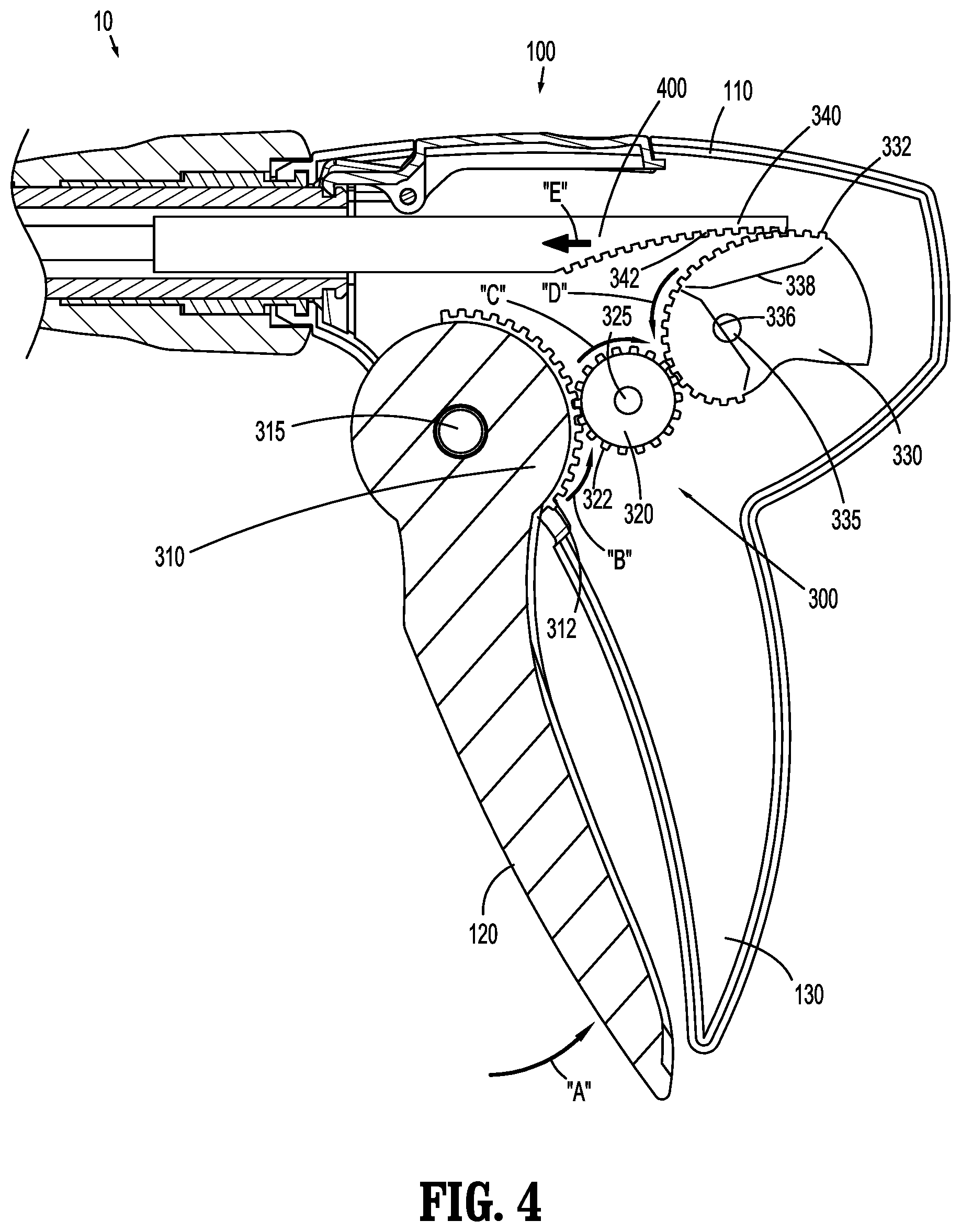
[0019] Generally, actuation of movable handle 120 relative to stationary handle 130 causes rotation of various portions of drive gear mechanism 300 relative to housing 110 of handle assembly 100, which causes longitudinal translation of drive member 400 relative to housing 110 of handle assembly 100. More particularly, and with specific reference to FIGS. 3 and 4, actuation of movable handle 120 in the general direction of arrow "A" causes rotation of first gear 310 about first pin 315 in the general direction of arrow "B." This rotation of first gear 310 causes a corresponding rotation of second gear 320 about second pin 325 in the general direction of arrow "C," due to the engagement between teeth 312 of first gear 310 and teeth 322 of second gear 320. This rotation of second gear 320 causes a corresponding rotation of third gear 330 about third pin 335 in the general direction of arrow "D," due to the engagement between teeth 322 of second gear 320 and teeth 332 of third gear 330. Finally, this rotation of third gear 330 causes longitudinal (e.g., distal) translation of drive member 400 in the general direction of arrow "E," due to the engagement between teeth 332 of third gear 330 and teeth 342 of fourth gear 340.
[0020] With more particular reference to drive gear mechanism 300, first gear 310, second gear 320 and fourth gear 340 each include a single radius, which may be the same or different from each other. For example, the radius of first gear 310 may be from about 0.6 inches to about 0.9 inches (e.g., equal to about 0.75 inches), the radius of second gear 320 may be from about 0.17 inches to about 0.55 inches (e.g., equal to about 0.375 inches), and the radius of fourth gear 340 may be from about 0.75 inches to about 1.25 inches (e.g., equal to about 1.0 inches). While particular ranges of radiuses are disclosed, first gear 310, second gear 320, and fourth gear 340 may have radiuses outside of these ranges without departing from the scope of the disclosure.
[0021] Third gear 330 is a variable-radius gear or nautilus gear. That is, a first portion 336 of third gear 330 (e.g., the portion that engages second gear 320) has a first radius, while a second portion 338 of third gear 330 (e.g., the portion that engages fourth gear 340) has a second radius. In the illustrated embodiment, the first radius (e.g., at first portion 336) of third gear 330 is smaller than the second radius (e.g., at second portion 338) of third gear 330. For example, the first radius may be from about 0.17 inches to about 0.55 inches (e.g., equal to about 0.375 inches), and the second radius may be from about 0.75 inches to about 1.25 inches (e.g., equal to about 1.0 inches). Further, the first radius of first portion 336 of third gear 330 may be equal to the radius of second gear 320, with which first portion 336 of third gear 330 engages, and the second radius of second portion 338 of third gear 330 may be equal to the radius of fourth gear 340, with which second portion 338 of third gear 330 engages. While particular ranges of radiuses are disclosed, first portion 336 and second portion 338 of third gear 330 may have radiuses outside of these ranges without departing from the scope of the disclosure.
[0022] The variable-radius third gear 330 results in differing amounts of mechanical advantage provided by movable handle 120 during a single actuation stroke. For example, the mechanical advantage of the initial actuation of movable handle 120 may be about 0.75:1 for the first approximately 10.degree. of actuation, which may distally advance drive member 200 about 2.0 inches. In furtherance of this example, the mechanical advantage of the subsequent actuation of movable handle 120 may be about 5:1 for the next approximately 30.degree. of actuation, which may distally advance drive member 400 about 0.3 inches. In embodiments, the initial actuation of movable handle 120 may correspond with loading or advancing a surgical fastener or clip, and the subsequent actuation of movable handle 120 may correspond with firing, forming or deploying the surgical fastener or clip through or onto tissue. While particular mechanical advantages, stroke lengths, and advancement distances of drive member 400 are disclosed, other mechanical advantages, stroke lengths, and advancement distances of drive member 400 that are higher and/or lower than these values are contemplated without departing from the scope of the disclosure, for instance depending on the particular type of instrument, surgical procedure, type of fastener used, etc.
[0023] Thus, the variable-radius third gear 330 reduces the force that must be applied to movable handle 120 by a user, while ensuring that adequate force and advancement distance of drive member 400 is produced to complete the surgical task.
[0024] Additionally, drive gear mechanism 300 may include a total of three gears instead of four gears. In such embodiments, second gear 320 is absent, first gear 310 directly engages first portion 336 of third gear 330, and second portion 338 of third gear 330 engages fourth gear 340.
[0025] It should be understood that the foregoing description is only illustrative of the disclosure. Various alternatives and modifications can be devised by those skilled in the art without departing from the disclosure. Accordingly, the disclosure is intended to embrace all such alternatives, modifications and variances. The embodiments described with reference to the attached drawing figures are presented only to demonstrate certain examples of the disclosure. Other elements that are insubstantially different from those described above and/or in the appended claims are also intended to be within the scope of the disclosure.
* * * * *
D00000
D00001
D00002
D00003
D00004
XML
uspto.report is an independent third-party trademark research tool that is not affiliated, endorsed, or sponsored by the United States Patent and Trademark Office (USPTO) or any other governmental organization. The information provided by uspto.report is based on publicly available data at the time of writing and is intended for informational purposes only.
While we strive to provide accurate and up-to-date information, we do not guarantee the accuracy, completeness, reliability, or suitability of the information displayed on this site. The use of this site is at your own risk. Any reliance you place on such information is therefore strictly at your own risk.
All official trademark data, including owner information, should be verified by visiting the official USPTO website at www.uspto.gov. This site is not intended to replace professional legal advice and should not be used as a substitute for consulting with a legal professional who is knowledgeable about trademark law.