Sealing Arrangement Of A Wheel Bearing
EICHELMANN; Frank ; et al.
U.S. patent application number 16/088517 was filed with the patent office on 2020-09-24 for sealing arrangement of a wheel bearing. This patent application is currently assigned to SCHAEFFLER TECHNOLOGIES AG & CO. KG. The applicant listed for this patent is SCHAEFFLER TECHNOLOGIES AG & CO. KG. Invention is credited to Frank EICHELMANN, Andreas KAISER, Christian MOCK, Jakob RUTZ.
| Application Number | 20200300304 16/088517 |
| Document ID | / |
| Family ID | 1000004886285 |
| Filed Date | 2020-09-24 |
| United States Patent Application | 20200300304 |
| Kind Code | A1 |
| EICHELMANN; Frank ; et al. | September 24, 2020 |
SEALING ARRANGEMENT OF A WHEEL BEARING
Abstract
A sealing arrangement comprising a carrier element connecting to a first bearing part, wherein the carrier element further includes an elastic element that includes a sealing lip, and a cavity between the first bearing part and a second bearing part, wherein the cavity is delimited by the carrier element, wherein the carrier element includes at least one aperture at a radial level of the cavity and the at least one aperture is sealed by a diaphragm connected to the carrier element, wherein at least one protective lip is provided on an opposite side of the diaphragm, and wherein the at least one protective lip is formed at the elastic element.
| Inventors: | EICHELMANN; Frank; (Donnersdorf, DE) ; RUTZ; Jakob; (Hambach, DE) ; KAISER; Andreas; (Werneck, DE) ; MOCK; Christian; (Schweinfurt, DE) | ||||||||||
| Applicant: |
|
||||||||||
|---|---|---|---|---|---|---|---|---|---|---|---|
| Assignee: | SCHAEFFLER TECHNOLOGIES AG &
CO. KG Herzogenaurach DE |
||||||||||
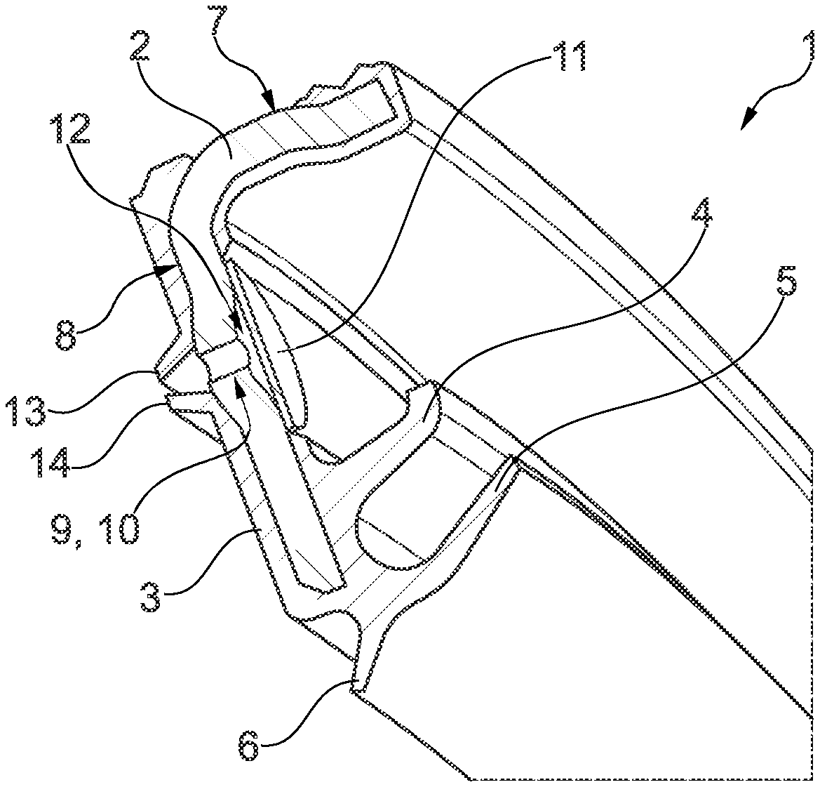
| Family ID: | 1000004886285 | ||||||||||
| Appl. No.: | 16/088517 | ||||||||||
| Filed: | January 25, 2017 | ||||||||||
| PCT Filed: | January 25, 2017 | ||||||||||
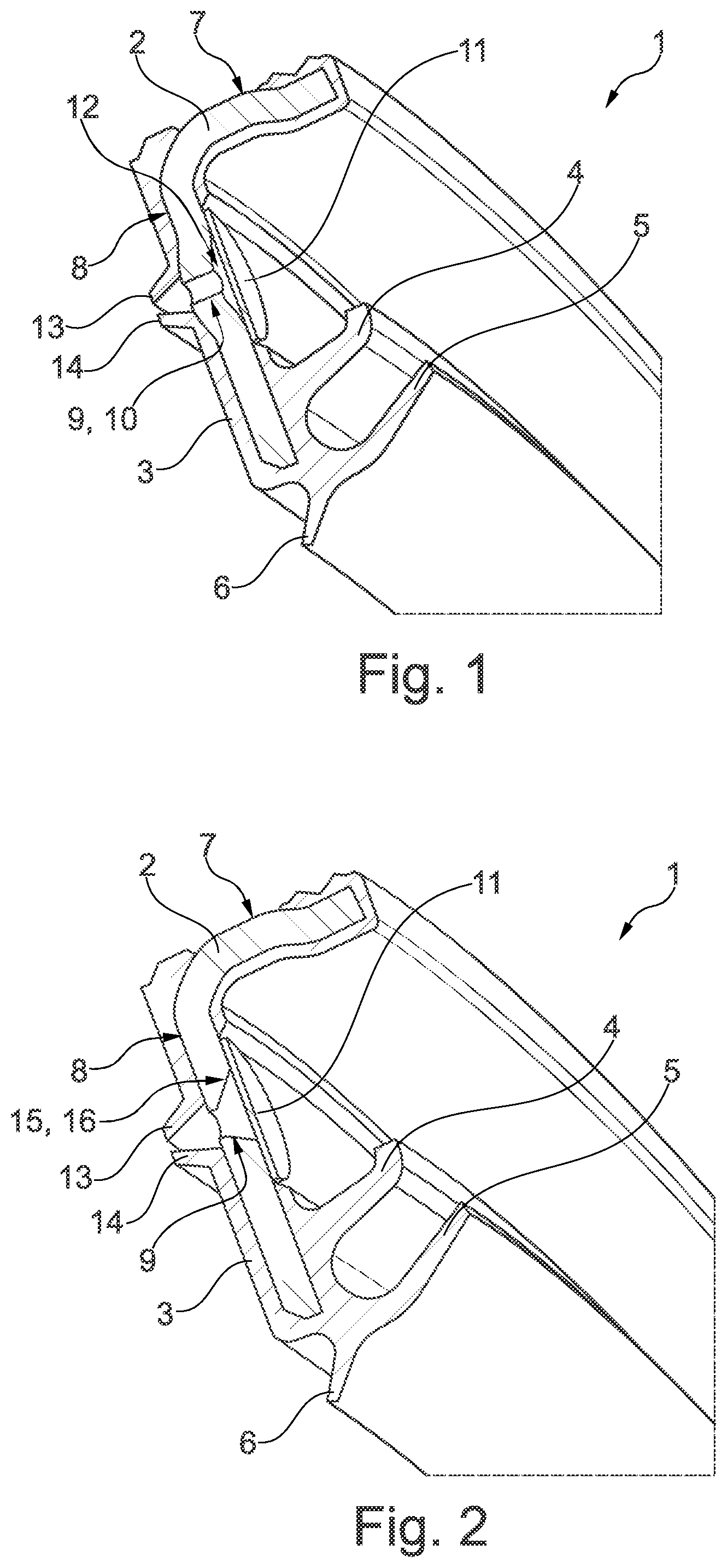
| PCT NO: | PCT/DE2017/100047 | ||||||||||
| 371 Date: | September 26, 2018 |
| Current U.S. Class: | 1/1 |
| Current CPC Class: | F16C 33/726 20130101; F16C 2326/02 20130101; F16C 33/7876 20130101 |
| International Class: | F16C 33/72 20060101 F16C033/72; F16C 33/78 20060101 F16C033/78 |
Foreign Application Data
| Date | Code | Application Number |
|---|---|---|
| Mar 30, 2016 | DE | 102016205181.4 |
Claims
1. A sealing arrangement of a wheel bearing having an inner bearing part and an outer bearing part, between which rolling bodies are guided, wherein the sealing arrangement comprises: a carrier element connected to one of the inner bearing part or the outer bearing part, and an elastic element is provided on the carrier element, wherein the elastic element includes at least one sealing lip; wherein a cavity is formed between the inner bearing part and the outer bearing part, wherein the cavity is delimited by the carrier element or elastic element; wherein the carrier element or the elastic element features at least one aperture at a radial level of the cavity, and wherein the at least one aperture is sealed by a diaphragm connected to the carrier element, wherein the diaphragm is provided on an opposite side of at least one protective lip is formed on the carrier element or elastic element.
2. The sealing arrangement of claim 1, wherein the at least one protective lip is formed by the elastic element.
3. The sealing arrangement of claim 1, wherein an air volume is provided between the diaphragm and the carrier element.
4. The sealing arrangement of claim 3, wherein the air volume is formed by a depression provided at the carrier element.
5. The sealing arrangement of claim 2, wherein the at least one aperture includes a chamfer.
6. The sealing arrangement of claim 1, wherein the at least one aperture is drilled, punched, milled, or lasered.
7. The sealing arrangement of claim 1, wherein the carrier element is manufactured out of a metal or plastic material.
8. A sealing arrangement, comprising: a carrier element connecting to a first bearing part, wherein the carrier element further includes an elastic element that includes a sealing lip; and a cavity between the first bearing part and a second bearing part, wherein the cavity is delimited by the carrier element, wherein the carrier element includes at least one aperture at a radial level of the cavity and the at least one aperture is sealed by a diaphragm connected to the carrier element, wherein at least one protective lip is provided on an opposite side of the diaphragm, and wherein the at least one protective lip is formed at the elastic element.
9. The sealing arrangement of claim 8, wherein the sealing arrangement includes two protective lips surrounding the aperture.
10. The sealing arrangement of claim 8, wherein the aperture is created by using a bore hole that includes a chamfer.
11. The sealing arrangement of claim 10, wherein a diameter of the bore hole increases in a direction of the diaphragm.
12. The sealing arrangement of claim 8 wherein the at least one aperture includes a chamfer.
13. The sealing arrangement of claim 8, wherein the sealing arrangement includes a second protective lip is provided at the carrier element.
14. The sealing arrangement of claim 13, wherein both of the protective lips are arranged in a V-shape formation.
15. The sealing arrangement of claim 8, wherein the diaphragm is indirectly connected to the carrier element.
16. The sealing arrangement of claim 8, wherein the at least one aperture includes a plurality of apertures evenly distributed along a circumference of the carrier element.
17. The sealing arrangement of claim 8, wherein the at least one aperture includes a plurality of apertures with a radial offset towards each other.
18. A sealing arrangement, comprising: a carrier element connecting to a first bearing part, wherein the carrier element further includes an elastic element that includes a sealing lip; and a cavity between the first bearing part and a second bearing part, wherein the cavity is delimited by the carrier element, wherein the elastic element includes at least one aperture at a radial level of the cavity and the aperture is sealed by a diaphragm connected to the elastic element, wherein at least one protective lip is provided on an opposite side of the diaphragm, and wherein the at least one protective lip is formed at the carrier element.
19. The sealing arrangement of claim 18, wherein the diaphragm is indirectly connected to the elastic element.
20. The sealing arrangement of claim 18, wherein the carrier element is formed in an L-shape, C-shape, or S-shape.
Description
CROSS-REFERENCE TO RELATED APPLICATIONS
[0001] This application is the U.S. National Phase of PCT/DE2017/100047 filed Jan. 25, 2017, which claims priority to DE 102016205181.4 filed Mar. 30, 2016, the entire disclosures of which are incorporated by reference herein.
TECHNICAL FIELD
[0002] The disclosure relates to a sealing arrangement of a wheel bearing.
BACKGROUND
[0003] In order to achieve a long lifespan, wheel bearings of motor vehicles require double-sided sealings of the interior which are filled with lubricant and which contain the rolling bodies. To accomplish this, centrifugal sheets are used, which form a sealing labyrinth along with the sealing lips.
[0004] A sealed bearing arrangement is known from the DE 10 2010 055 178. The bearing arrangement features a sealing arrangement on both sides of the axial ends. This sealing arrangement consists of a sealing ring, features several apertures that are distributed along the circumference, which are sealed in a semipermeable manner by using a elastomer diaphragm and which form a gas channel.
SUMMARY
[0005] It is the objective of the present disclosure, to provide a sealing arrangement, which seals for the duration of the usage in both a secure manner, as well which ensures a ventilation system for a pressure compensation in the bearing.
[0006] In line with the disclosure, this task is accomplished by using a sealing arrangement of a wheel bearing with a first bearing part and with a second bearing part that is connected in one piece with a wheel bearing flange, between which rolling bodies are guided, wherein the sealing arrangement comprises the following:
[0007] a carrier element, which is connected to one of the two bearing parts and wherein an elastic element is provided on the carrier element, wherein the elastic element features at least one sealing lip,
[0008] wherein a cavity is configured between the first bearing part and the second bearing part, which cavity is delimited by using the carrier element and/or the elastic element, and
[0009] wherein the carrier element and/or the elastic element feature at least one aperture at the radial level of the cavity, and wherein the at least one aperture is sealed by way of a diaphragm, and wherein the diaphragm is connected directly and/or indirectly to the carrier element, wherein at least one protective lip is provided on the opposite side of the diaphragm, and wherein the a least one protective lip is formed at the elastic element and/or at the carrier element.
[0010] The sealing arrangement according to the disclosure features a diaphragm, which is connected directly and/or indirectly to the carrier element and which seals the at least one aperture. On the opposite side of the diaphragm, at least one protective lip is provided at the carrier element. This protective lip may be made of an elastomer. The protective lip is hereby either directly connected to the carrier element or the protective lip is formed by using the elastic element, which already forms the sealing lip. The purpose of the protective lip is to protect the diaphragm against contamination such a grease, oil, water and the like. Advantageously, two protective lips are intended, which are approximately arranged in a V-shape formation, in order to form a narrow gap. This narrow gap further ensures the function of the diaphragm and thereby the ventilation for a pressure equalization when temperature differences occur.
[0011] The at least one aperture that is provided in the carrier element can be designed as a bore hole, slot, or the like. If the carrier element features several apertures, these are arranged in a distributed manner along the circumference. The apertures can be provided e.g. in an evenly distributed manner and/or with a radial offset towards each other.
[0012] The carrier element can be formed in an L-, C- or S-shape. It may also be possible that the carrier element does not feature at least one sealing lip, but that it serves as a stop face for at least one sealing lip.
[0013] According to one alternative embodiment of the disclosure, the at least one protective lip is formed by using the elastic element. The advantage of this is that the protective lip can be additionally formed on the carrier element in one manufacturing step when the elastic element is applied, which in turn forms the at least one sealing lip. A separate manufacturing step would thus be avoided. Overall, a simple and cost-effective production is thus provided and ensured.
[0014] According to one embodiment of the disclosure, an air volume is provided between the diaphragm and the carrier element. By use the intended air volume it is ensured that a ventilation of the interior of the bearing can be carried out.
[0015] The air volume may be created by using a depression provided on the carrier element. The depression may be chamfered or the like. Such an embodiment of the disclosure serves to increase the active surfaces of the diaphragm. This has the result, that a larger portion of the surface of the diaphragm can be used for the ventilation.
[0016] According to one embodiment of the disclosure, the at least one aperture is drilled, punched, milled and/or lasered.
[0017] The carrier element may be manufactured out of a metal or plastic material. The stiffness of the sealing arrangement is thus ensured.
BRIEF DESCRIPTION OF THE DRAWINGS
[0018] In the following, two embodiments of the disclosure are depicted by means of two figures. It is shown:
[0019] FIG. 1 a section from a sealing arrangement of a wheel bearing in line with the disclosure according to a first embodiment,
[0020] FIG. 2 a section from a sealing arrangement of a wheel bearing in line with the disclosure according to a second embodiment.
DETAILED DESCRIPTION
[0021] FIG. 1 depicts a section of a sealing arrangement 1 according to the disclosure of a wheel bearing that is not shown in detail in accordance with a first embodiment.
[0022] The sealing arrangement 1 comprises a carrier element 2, which is formed in an L-shape and which features a first section 7 and a second section 8. By using the first section, carrier element 2 is connected to one of the bearing parts of the wheel bearing that are not shown in detail. An elastic element 3 is connected to carrier element 2. The elastic element 3 features three sealing lips 4, 5, 6 in this embodiment. These sealing lips 4, 5, 6 either lie against a further metal sheet or at one of the two bearing parts of the wheel bearing.
[0023] Second section 8 of carrier element 2 features at least one aperture 9. It is formed as a bore hole 10 with a constant diameter. Aperture 9 is sealed on one side of the second section by using a diaphragm 11. Diaphragm 11 is hereby directly connected to carrier element 2. The second section 8 features a depression 12 in the region of diaphragm 11, which creates an air volume between diaphragm 11 and carrier element 2. This causes an increase in the active surfaces of diaphragm 11.
[0024] Two protective lips 13, 14 surrounding the aperture are provided on the opposite side of diaphragm 11. The two protective lips 13, 14 are formed by using the elastic element 3 and are thus connected to the second section 8 of the carrier element. The protective lips 13, 14 run towards each other in a V-shape and thereby form a narrow gap in the direction of aperture 9. Such an arrangement ensures that diaphragm 11 is protected against contamination such as bearing oil or grease.
[0025] In the following, a second embodiment will be described with reference to FIG. 2. Identical components are referred to by the same reference signs as in the preceding FIG. 1. The description of FIG. 2 is thus limited to components that are different.
[0026] Just like FIG. 1, FIG. 2 depicts a section of a sealing arrangement 1 according to the disclosure of a wheel bearing that is not shown in detail. In this embodiment, aperture 9 is implemented in a different way.
[0027] Aperture 9 is created by use of a bore hole 15 with a chamfer 16. The diameter of bore hole 15 may increase in the direction of diaphragm 11. This causes an increase of the active surface of diaphragm 11.
LIST OF REFERENCE SIGNS
[0028] 1 Sealing arrangement [0029] 2 Carrier element [0030] 3 Elastic element [0031] 4 Sealing lip [0032] 5 Sealing lip [0033] 6 Sealing lip [0034] 7 First section [0035] 8 Second section [0036] 9 Aperture [0037] 10 Bore hole [0038] 11 Diaphragm [0039] 12 Depression [0040] 13 Protective lip [0041] 14 Protective lip [0042] 15 Bore hole [0043] 16 Chamfer
* * * * *
D00000
D00001
XML
uspto.report is an independent third-party trademark research tool that is not affiliated, endorsed, or sponsored by the United States Patent and Trademark Office (USPTO) or any other governmental organization. The information provided by uspto.report is based on publicly available data at the time of writing and is intended for informational purposes only.
While we strive to provide accurate and up-to-date information, we do not guarantee the accuracy, completeness, reliability, or suitability of the information displayed on this site. The use of this site is at your own risk. Any reliance you place on such information is therefore strictly at your own risk.
All official trademark data, including owner information, should be verified by visiting the official USPTO website at www.uspto.gov. This site is not intended to replace professional legal advice and should not be used as a substitute for consulting with a legal professional who is knowledgeable about trademark law.