Oversized Switchgear Trailer For Electric Hydraulic Fracturing
Hinderliter; Brandon ; et al.
U.S. patent application number 16/824432 was filed with the patent office on 2020-09-24 for oversized switchgear trailer for electric hydraulic fracturing. This patent application is currently assigned to U.S. Well Services, LLC. The applicant listed for this patent is U.S. Well Services, LLC. Invention is credited to Brandon Hinderliter, Jared Oehring.
| Application Number | 20200300073 16/824432 |
| Document ID | / |
| Family ID | 1000004735660 |
| Filed Date | 2020-09-24 |


View All Diagrams
| United States Patent Application | 20200300073 |
| Kind Code | A1 |
| Hinderliter; Brandon ; et al. | September 24, 2020 |
OVERSIZED SWITCHGEAR TRAILER FOR ELECTRIC HYDRAULIC FRACTURING
Abstract
A hydraulic fracturing system for fracturing a subterranean formation includes a primary switchgear arranged on a support structure. The system also includes a secondary switchgear, arranged on the support structure, the secondary switchgear positioned separately from the primary switchgear and within an enclosure, the secondary switchgear receiving an electrical input from the primary switchgear and including an plurality of feed connections for supplying electrical power to a plurality of fracturing equipment.
| Inventors: | Hinderliter; Brandon; (Houston, TX) ; Oehring; Jared; (Houston, TX) | ||||||||||
| Applicant: |
|
||||||||||
|---|---|---|---|---|---|---|---|---|---|---|---|
| Assignee: | U.S. Well Services, LLC Houston TX |
||||||||||
| Family ID: | 1000004735660 | ||||||||||
| Appl. No.: | 16/824432 | ||||||||||
| Filed: | March 19, 2020 |
Related U.S. Patent Documents
| Application Number | Filing Date | Patent Number | ||
|---|---|---|---|---|
| 62821138 | Mar 20, 2019 | |||
| Current U.S. Class: | 1/1 |
| Current CPC Class: | H02J 3/46 20130101; H02B 1/06 20130101; H02B 1/52 20130101; H02J 3/381 20130101; H02J 3/06 20130101; E21B 43/26 20130101; F04B 17/03 20130101; H02J 3/007 20200101; H02B 1/202 20130101; H02B 1/305 20130101; H02J 2310/40 20200101; F04B 35/04 20130101; H02B 1/24 20130101; F01D 15/10 20130101; H02B 7/06 20130101; H02B 1/205 20130101 |
| International Class: | E21B 43/26 20060101 E21B043/26; H02B 7/06 20060101 H02B007/06; H02B 1/20 20060101 H02B001/20; H02B 1/24 20060101 H02B001/24; H02B 1/06 20060101 H02B001/06; H02B 1/30 20060101 H02B001/30; H02B 1/52 20060101 H02B001/52; H02J 3/38 20060101 H02J003/38; H02J 3/46 20060101 H02J003/46; H02J 3/06 20060101 H02J003/06; H02J 3/00 20060101 H02J003/00; F04B 17/03 20060101 F04B017/03; F04B 35/04 20060101 F04B035/04; F01D 15/10 20060101 F01D015/10 |
Claims
1. A hydraulic fracturing system for fracturing a subterranean formation, comprising: a primary switchgear, arranged on a support structure, the primary switchgear electrically coupled to a power source to receive power from the power source; a secondary switchgear, arranged on the support structure, the secondary switchgear positioned separately from the primary switchgear and within an enclosure, the secondary switchgear receiving an electrical input from the primary switchgear and including a plurality of feed connections for supplying electrical power to a plurality of fracturing equipment; and support equipment, arranged on the support structure, the support equipment providing one or more services to at least the secondary switchgear.
2. The system of claim 1, further comprising: a walkway arranged proximate the primary switchgear, the walkway extending along at least a portion of the support structure and providing access to a door of the enclosure housing the secondary switchgear.
3. The system of claim 1, wherein the support equipment includes at least one of HVAC equipment, a control power transformer, a battery, or external controls.
4. The system of claim 1, further comprising: a cable routing area positioned to extend from the primary switchgear to the secondary switchgear, the cable routing area being predetermined and consolidating one or more cables utilized to transmit electrical energy from the primary switchgear to the secondary switchgear.
5. The system of claim 1, wherein at least one of the primary switchgear or the secondary switchgear is a multi-bus power distribution system, the multi-bus power distribution system comprising: a high amperage load sharing bus; at least one low amperage distribution bus; and at least one bus connector arranged between the high amperage low sharing bus and the at least one low amperage distribution bus.
6. The system of claim 5, wherein the high amperage load sharing bus receives energy from one or more generators of the power source at one or more main breakers, the main breakers directing the energy to the high amperage load sharing bus for distribution to fracturing equipment of the plurality of fracturing equipment.
7. The system of claim 1, wherein the support structure includes at least one of a trailer, a skid, or a truck.
8. The system of claim 1, wherein the enclosure is climate controlled.
9. The system of claim 1, wherein a length of the support structure is less than or equal to a length of as associated support structure of one or more components of the hydraulic fracturing system.
10. The system of claim 1, wherein at least one of the primary switchgear or the secondary switchgear is a single-bus power distribution system, the single-bus power distribution system comprising: a single common high amperage bus receiving energy from one or more generators of the power source at one or more main breakers, the single common high amperage bus distributing the power to a feeder circuit.
11. The system of claim 1, further comprising a load sharing circuit including the primary switchgear and the secondary switchgear, the load sharing circuit comprising: a high amperage bus receiving energy from one or more generators of the power source at one or more main breakers, the one or more main breakers supplying the energy proximate a center of the high amperage bus, wherein a total load coupled to feed connections of the plurality of feed connections on each side of the high amperage bus is less than a capacity of at least one of the one or more main breakers.
12. An electrical distribution system for providing electrical to hydraulic fracturing equipment, comprising: a primary bus, arranged on a support structure, electrically coupled to at least one generator providing electrical power to a breaker coupled to the primary bus and also arranged on the support structure; and a secondary bus, arranged on the support structure, electrically coupled to the primary bus via at least one cable, the secondary bus being positioned within an enclosure and including a plurality of feed connections for supplying electrical power to at least one piece of fracturing equipment.
13. The system of claim 12, wherein the support structure includes at least one of a trailer, a skid, or a truck.
14. The system of claim 12, wherein the enclosure is climate controlled and positioned separately from the primary bus.
15. The system of claim 12, wherein the primary bus and the secondary bus form a multi-bus power distribution system, the primary bus corresponding to a high amperage load sharing bus and the secondary bus corresponding to at least one low amperage distribution bus.
16. The system of claim 15, further comprising: at least one bus connector arranged between the primary bus and the secondary bus.
17. The system of claim 12, wherein the primary bus and the secondary bus form a load sharing circuit, wherein one or more main breakers supply energy proximate a center of the primary bus, wherein a total load coupled to feed connections of the plurality of feed connections on each side of the primary bus is less than a capacity of at least one of the one or more main breakers.
18. A hydraulic fracturing system for fracturing a subterranean formation, comprising: at least one generator; at least one switchgear system receiving electrical power from the generator, the switchgear system including a primary bus and a secondary bus both arranged on a first support structure; and an electric powered pump, arranged on a second support structure, the electric powered pump coupled to a well associated with the subterranean formation and powered by at least one electric motor, the electric powered pump configured to pump fluid into a wellbore associated with the well at a high pressure so that the fluid passes from the wellbore into the subterranean formation and fractures the subterranean formation.
19. The system of claim 18, further comprising: a housing on the first support structure, the housing forming an enclosure around the second sub; and a plurality of feeder connections associated with the secondary bus.
20. The system of claim 18, wherein the first support structure includes at least one of a trailer, a skid, or a truck.
Description
CROSS-REFERENCE TO RELATED APPLICATIONS
[0001] This application claims priority to and the benefit of co-pending U.S. Provisional Patent Application Ser. No. 62/821,138 filed Mar. 20, 2019 titled "OVERSIZED SWITCHGEAR TRAILER FOR ELECTRIC HYDRAULIC FRACTURING," the full disclosure of which is hereby incorporated herein by reference in its entirety for all purposes.
BACKGROUND
1. Technical Field
[0002] This disclosure relates generally to hydraulic fracturing and more particularly to systems and methods for switchgear and power distribution systems.
2. Background
[0003] Hydraulic fracturing operations may be performed at remote locations, and as a result, trailers and other equipment are utilized to transport equipment between well sites. However, certain regulations may restrict loads along roadways, which may drive one or more design considerations for equipment utilized at well sites. These smaller, compact trailers may lead to comprises to design that would otherwise not be desirable.
SUMMARY
[0004] The present disclosure is directed to configurations for trailers utilized in hydraulic fracturing operations.
[0005] In an embodiment, a hydraulic fracturing system for fracturing a subterranean formation includes a primary switchgear, arranged on a support structure, the primary switchgear electrically coupled to a power source to receive power from the power source. The system also includes a secondary switchgear, arranged on the support structure, the secondary switchgear positioned separately from the primary switchgear and within an enclosure, the secondary switchgear receiving an electrical input from the primary switchgear and including an plurality of feed connections for supplying electrical power to a plurality of fracturing equipment. The system further includes support equipment, arranged on the support structure, the support equipment providing one or more services to at least the secondary switchgear.
[0006] In an embodiment an electrical distribution system for providing electrical to hydraulic fracturing equipment includes a primary bus, arranged on a support structure, electrically coupled to at least one generator providing electrical power to a breaker coupled to the primary bus and also arranged on the support structure. The system also includes a secondary bus, arranged on the support structure, electrically coupled to the primary bus via at least one cable, the secondary bus being positioned within an enclosure and including a plurality of feed connections for supplying electrical power to at least one piece of fracturing equipment.
[0007] In an embodiment, a hydraulic fracturing system for fracturing a subterranean formation includes at least one generator and at least one switchgear system receiving electrical power from the generator, the switchgear system including a primary bus and a secondary bus both arranged on a first support structure. The system also includes an electric powered pump, arranged on a second support structure, the electric powered pump coupled to a well associated with the subterranean formation and powered by at least one electric motor, the electric powered pump configured to pump fluid into a wellbore associated with the well at a high pressure so that the fluid passes from the wellbore into the subterranean formation and fractures the subterranean formation.
[0008] In an embodiment, multiple components of a switchgear system are incorporated into a single trailer, which ray be an oversized trailer, to simplify operations at the well site. In various embodiments, incorporation of components onto a single trailer may eliminate certain components, such as cables, which may also reduce costs.
[0009] Embodiments of the present disclosure may facilitate advantageous configurations for trailers utilized at a well site that my reduce redundancy, eliminate wiring at the well site, and incorporate remote evaluation and monitoring capabilities.
[0010] Embodiments may provide for elimination or reduction of several redundant switchgear breakers. Current configurations having multiple independent switchgear trailers may include separate, independent incoming and outgoing breakers, which may be used to comply with various professional codes. For example, if the switchgear trailers are divided up into a Common Bus Switchgear trailer and two or more Distribution Switchgear trailers, then each one needs incoming and outgoing breakers. Embodiments of the present disclosure may consolidate these components onto a single trailer unit, and as a result, only a single set of incoming and outgoing breakers are used for the entire system.
[0011] Embodiments may provide for elimination or reduction of interconnecting cables. In various embodiments, cables between the individual switchgear trailers will no longer be needed or a number used may be reduced. Due to the possible amperage between switchgear trailers, these cables are normally very large and heavy, which requires extra man power for rig up and rig down. They are also expensive and require additional insulation resistance tests before each energization. Elimination or reduced may reduce costs and complexity at the well site.
[0012] Embodiments may provide for remote 86 lockout relay controls incorporated into the system. The 86 lockout relays, which are tripped in the event of an electrical fault, can be reset externally using embodiments of the present disclosure. This prevents technicians from either: 1) interrupting operations by de-energizing the entire switchgear trailer so they can safely enter the switchgear house to reset the breaker, or 2) using arc flash suits, which can be difficult to put on in an oilfield environment and can possibly fail in the event of an arc flash.
[0013] Embodiments may provide for remote breaker open and close systems to be incorporated into the system. The same benefits will apply as to the 86 lockout relay controls described above.
[0014] Embodiments may provide for remote ground check monitoring incorporated into the system. As a result, technicians are provided the ability to ensure cable integrity as well as positive cable coupling on any input or output without entering the switchgear enclosure, which is undesirable if any piece of equipment is energized.
[0015] Embodiments may provide for remote human machine interfaces (HMI) to be incorporated into the system. An HMI or GUI can be used to allow technicians to interface with the breakers and relays without being in the breaker enclosure. Control software instead of mechanical switches will allow access to more information and control options in a much smaller package which can be a minimum of one screen.
[0016] Embodiments may provide for remote monitoring incorporated into the system. Ethernet (or serial) support may enable an onsite data van for frac operations to monitor and control individual breaker settings and statuses. This information may be streamed o the data van in real (or near-real) time to enable an operator to react to readings. Furthermore, in various embodiments, alarms and automated progressing, among other features, may be utilized in order to react to certain data readings.
[0017] Embodiments may provide for remote data collection incorporated into the system. When data is sent to the data van, via Ethernet (or serial), it may also be collected and transmitted to a cloud based storage system for historical analysis as well as troubleshooting support. In various embodiments, the storage may also be local. For example, data may be streamed in real (or near-real) time to the cloud system, where it may be accessible via a remote client device. The data may be raw data or processed data, which may be processed using one or more computer systems associated with a distributed computing environment. Moreover, as will be appreciated, the data may be encrypted or otherwise access-restricted.
[0018] Embodiments may provide for remote laptop USB ports. In various embodiments, this may be an external port so technicians may download and observe detailed information as well as upload and download breaker settings without entering the energized switchgear housing. For example, the ports may be arranged external of an enclosure to enable technicians to gain data access from a remote location and/or from outside of the enclosure
[0019] Embodiments may provide for external beaker indicator lights. Lights will give technicians and other onsite personnel a quick way to verifying breaker status such as Open/Closed/Tripped. The lights may be LED lights that are color coded and/or may involve individual lights associated with each status.
[0020] Embodiments may provide for shore power/battery power. The batteries may provide power for lights and/or initial breaker closing before a small onboard transformer can draw power to operate breakers and other ancillary functions. Often times, in cold weather or during startup with equipment difficulties, it is possible to deplete the batteries. A shore power connection provides an option for technicians to quickly and easily recharge the batteries from a small generator or light plant.
[0021] Embodiments may provide for battery heaters. This is to increase the operational longevity of the batteries as well as increase amp-hours in colder weather.
[0022] Adequate HVAC may be incorporated into the system. Heating and cooling keeps condensation out of sensitive electronics as well keeps them from overheating. Switchgear trailers of the present embodiments may be designed to maintain room temperature internally while operating is ambient temperatures of -25.degree. C. to 55.degree. C.
[0023] In various embodiments, the system may include at least 24 outgoing breakers. However, it should be appreciated that more outgoing breakers may be incorporated. As a result, power may be provided to 22 frac pumps and 2 blenders simultaneously.
[0024] In various embodiments, the system may include at least 2 incoming breakers. However, it should be appreciated that more incoming breakers may be incorporated. In various operations, power may be distributed from 2 larger block turbine generators (e.g., 30 MW and above) or up to 4 small block turbine generators (e.g., 10 MW and below). The incoming breakers for the new equipment may be positioned to accept power from large or small block turbine generators. Software settings can be changed to accommodate for either sized generator. Older generations of switchgear trailers could only accept power from 4 small turbine generators while certain designs can accept power from up to 3 large or small turbine generators, with the most common set up being one large turbine generator and one small turbine generator load sharing through a 3000 A common bus on the switchgear trailer.
[0025] Embodiments may provide for a compact switchgear. The feeder breakers (or outgoing) may be reduced to a 1200 A bus. This allows the components to be much more compact. single compact breaker can fit within a 15''.times.36'' or 26''.times.45'' section instead of the larger 3'.times.8'' profile of the incoming breakers.
[0026] Embodiments may provide for 3000 A or 2000 A bus bar sections. This configuration provides for load sharing multiple turbine generators on a common bus.
[0027] Embodiments may provide for 3000 A, 2000 A, or 1200 A bus bar sections. Such a configuration may enable power distributions to multiple individual power loads such as frac pumps, blenders, hydration units, sand equipment, water pumps, chemical mixers, data vans, etc.
[0028] Embodiments may provide for bus connectors (BCs). The use of incoming and outgoing breakers with a common bus for load sharing may be utilized in systems of the present disclosure. As a result, an economical platform which can fit enough capability onto a single trailer is provided. In various embodiments, using bus connectors between different bus segments that have no (or limited) external cable connections, enables safe distribution of power from high amperage bus sections to lower amperage rated bus sections. Bus connectors can be in the form of fuses, switches, fused switches, or breakers. Fuses and switches are generally more compact and cheaper than breakers. Switches also allow the advantage of providing technicians with a visible disconnect between bus work which is important during maintenance or troubleshooting tasks. However, switches may not be remotely controllable.
[0029] Embodiments may provide for a separate bus work. That is, differently rated bus bar sections can be used together on the same switchgear trailer. Accordingly, a 3000 A or 2000 A common bus for load sharing between multiple generators for the incoming breakers as well as lower rated 2000 A or 1200 A bus bar sections for smaller more compact switchgear breakers for the outgoing power distribution is provided.
[0030] Embodiments may provide for fused switches. In various embodiments, using fused switches for protection in between differently rated sections of bus bars is a cheaper and more compact alternative to using full sized breakers and relays.
[0031] Embodiments may provide for a divided current bus bar. As will be described below, a lower amperage rated bus bar would effectively load share more than its rated amperage. This would work by having the incoming power physically entering the bus work in the middle with the feeder breakers (power load) being distributed to either end of the bus work where either side could only draw half of the possible power load. This would cause a current divider, where the maximum amperage drawn by either side of the main breakers would be under the limits of the bus work. This reduces costs by for example, being able to use a 2000 A bus bar instead of a larger and costlier 3000 A bus bar.
[0032] Embodiments may provide for multiphase receptacles. If the power requirement is below a threshold, for example approximately 10 MW, then cables and receptacles can be used that are in a three phase conductor configuration with an embedded ground and ground check conductor all within a single cable jacket and receptacle housing. This reduces the amount of physical connections that are required as well as increasing safety and reducing EMF. Sometimes several cables are used in parallel to transmit large amounts of power while keeping the cables to a manageable size.
[0033] Embodiments may provide for single phase receptacles. To transmit power larger generators, a single phase cable scheme if often used. This method can use multiple single conductor cables per phase and an independent ground conductor. Ruggedized single conductor quick disconnecting receptacles are used to preserve stress cones which are often fragile and can fail if they are damaged or dirty. An alternative method is to use standard NEMA 2 hole lugs with indoor or outdoor stress cones to lug the cables directly to the busbars. However, such a configuration may include tradeoffs, such as shorter service life.
[0034] The mobile switchgear units of the present disclosure can be trailerized, skid mounted, or mounted on a bodyload truck.
[0035] Embodiments may provide for arc flash rating. Individual switchgear breakers can be rated as explosion proof, which means that arc flash suits are not required by personnel inside any enclosure as long as the breaker cabinets are closed. Moreover, the breakers may be unrated which means that personnel cannot safely enter the switchgear enclosures without an arc flash suit. Non-explosion rated gear is usually physically more compact. With non-explosion proof gear, features such as remote open/close, remote 86 lockout reset, and remote instrumentation may provide safe and seamless operations.
[0036] Embodiments may provide for generators. In embodiments, switchgear systems described herein can accept power from many types of power sources such as turbine generators, reciprocating generators, battery banks, utility power grids, etc.
[0037] Embodiments may provide for instrumentation that may be incorporated into the system, such as potential transformers (PTs) and current transformers (CTs) to monitor voltage and amperage levels on all breakers, buses, cables, fuses, and switches.
BRIEF DESCRIPTION OF DRAWINGS
[0038] Some of the features and benefits of the present disclosure having been stated, others will become apparent as the description proceeds when taken in conjunction with the accompanying drawings, in which:
[0039] FIG. 1 is a schematic plan view of an embodiment of a fracturing operation, in accordance with embodiments of the present disclosure;
[0040] FIG. 2 is a schematic diagram of an embodiment of a well site layout using multiple switchgear trailers, in accordance with embodiments of the present disclosure;
[0041] FIG. 3 is a schematic diagram of an embodiment of a wellsite including a consolidated switchgear trailer, in accordance with embodiments of the present disclosure;
[0042] FIG. 4 is a top plan view of an embodiment of the oversized switchgear trailer, in accordance with embodiments of the present disclosure;
[0043] FIG. 5 is a top plan view of an embodiment of an oversized switchgear trailer, in accordance with embodiments of the present disclosure;
[0044] FIG. 6 is a top plan view of an embodiment of an oversized switchgear trailer, in accordance with embodiments of the present disclosure;
[0045] FIGS. 7-13 provide perspective, side, and top plan views of embodiments of the oversized switchgear trailer, in accordance with embodiments of the present disclosure;
[0046] FIG. 14 is a schematic diagram of an embodiment of a multi-bus power distribution switchgear system, in accordance with embodiments of the present disclosure;
[0047] FIG. 15 is a top plan view of an embodiment of an oversized switchgear trailer, in accordance with embodiments of the present disclosure;
[0048] FIG. 16 is a schematic diagram of an embodiment of a consolidated trailer, in accordance with embodiments of the present disclosure;
[0049] FIG. 17 is a schematic diagram of an embodiment of a single bus power distribution switchgear system, in accordance with embodiments of the present disclosure; and
[0050] FIG. 18 is a schematic diagram of an embodiment of a load sharing configuration, in accordance with embodiments of the present disclosure.
[0051] While the disclosure will be described in connection with the preferred embodiments, it will be understood that it is not intended to limit the disclosure to that embodiment. On the contrary, it is intended to cover all alternatives, modifications, and equivalents, as may be included within the spirit and scope of the disclosure as defined by the appended claims.
DETAILED DESCRIPTION
[0052] The method and system of the present disclosure will now be described more fully hereinafter with reference to the accompanying drawings in which embodiments are shown. The method and system of the present disclosure may be in many different forms and should not be construed as limited to the illustrated embodiments set forth herein; rather, these embodiments are provided so that this disclosure will be thorough and complete, and will fully convey its scope to those skilled in the art. Like numbers refer to like elements throughout. In an embodiment, usage of the term "about" includes +/- 5% of the cited magnitude. In an embodiment, usage of the term "substantially" includes +/- 5% of the cited magnitude.
[0053] It is to be further understood that the scope of the present disclosure is not limited to the exact details of construction, operation, exact materials, or embodiments shown and described, as modifications and equivalents will be apparent to one skilled in the art. In the drawings and specification, there have been disclosed illustrative embodiments and, although specific terms are employed, they are used in a generic and descriptive sense only and not for the purpose of limitation.
[0054] When introducing elements of various embodiments of the present disclosure, the articles "a", "an", "the", and "said" are intended to mean that there are one or more of the elements. The terms "comprising", "including", and "having" are intended to be inclusive and mean that there may be additional elements other than the listed elements. Any examples of operating parameters and/or environmental conditions are not exclusive of other parameters/conditions of the disclosed embodiments. Additionally, it should be understood that references to "one embodiment", "an embodiment", "certain embodiments", or "other embodiments" of the present disclosure are not intended to be interpreted as excluding the existence of additional embodiments that also incorporate the recited features. Furthermore, reference to terms such as "above", "below", "upper", "lower", "side", "front", "back", or other terms regarding orientation or direction are made with reference to the illustrated embodiments and are not intended to be limiting or exclude other orientations or directions. Additionally, recitations of steps of a method should be understood as being capable of being performed in any order unless specifically stated otherwise. Furthermore, the steps may be performed in series or in parallel unless specifically stated otherwise.
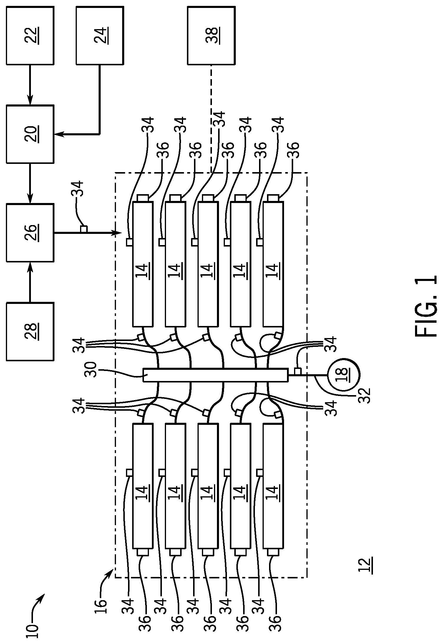
[0055] FIG. 1 is a plan schematic, view of an embodiment of a hydraulic fracturing system 10 positioned at a well site 12. In the illustrated embodiment, pumps 14 (which may be arranged on one or more trailers, skids, or the like), making up a pumping system 16, are used to pressurize a slurry solution for injection into a wellhead 18. An optional hydration unit 20 receives fluid from a fluid source 22 via a line, such as a tubular, and also receives additives from an additive source 24. In an embodiment, the fluid is water and the additives are mixed together and transferred to a blender unit 26 where proppant from a proppant source 28 may be added to form the slurry solution (e.g., fracturing slurry) which is transferred to the pumping system 16. The pumps 14 may receive the slurry solution at a first pressure (e.g., 80 psi to 160 psi) and boost the pressure to around 15,000 psi for injection into the wellhead 18. In certain embodiments, the pumps 14 are powered by electric motors.
[0056] After being discharged from the pump system 16, a distribution system 30, such as a manifold, receives the slurry solution for injection into the wellhead 18. The distribution system 30 consolidates the slurry solution from each of the pumps 14 and includes discharge piping 32 coupled to the wellhead 18. In this manner, pressurized solution for hydraulic fracturing may be injected into the wellhead 18.
[0057] In the illustrated embodiment, one or more sensors 34, 36 are arranged throughout the hydraulic fracturing system 10 to measure various properties related to fluid flow, vibration, and the like.
[0058] It should be appreciated that while various embodiments of the present disclosure may describe electric motors powering the pumps 14, in embodiments, electrical generation can be supplied by various different options, as well as hybrid options. Hybrid options may include two or more of the following electric generation options: Gas turbine generators with fuel supplied by field gas, CNG, and/or LNG, diesel turbine generators, diesel engine generators, natural gas engine generators, batteries, electrical grids, and the like. Moreover, these electric sources may include a single source type unit or multiple units. For example, there may be one gas turbine generator, two gas turbines generators, two gas turbine generators coupled with one diesel engine generator, and various other configurations.
[0059] In various embodiments, equipment at the well site may utilize 3 phase, 60 Hz, 690V electrical power. However, it should be appreciated that in other embodiments different power specifications may be utilized, such as 4160V or at different frequencies, such as 50 Hz. Accordingly, discussions herein with a particular type of power specification should not be interpreted as limited only the particularly discussed specification unless otherwise explicitly stated. Furthermore, systems described herein are designed for use in outdoor, oilfield conditions with fluctuations in temperature and weather, such as intense sunlight, wind, rain, snow, dust, and the like. In embodiments, the components are designed in accordance with various industry standards, such as NEMA, ANSI, and NEPA.
[0060] Current switchgear trailer designs have focused on traditional breakers and standard DOT size limits for trailers. In order to fit the appropriate switchgear required to safely power and operate an electric hydraulic fracturing fleet, two to three full size switchgear trailers have been required. On well sites requiring a common bus to combine the power of multiple generators, a minimum of three switchgear trailers has been used. On well sites were a split bus is allowed, where not all generators can load share, a minimum of two switchgear trailers will be required. These historical requirements are also for fracturing fleets that will be used for single well operations on shallow shale formations that use a relatively lower Hydraulic Horsepower (HHP). Many modern fleets that perform zipper frac operations (simultaneous operations on two or more wells) on deep wells (higher well pressure) will require more HHP and therefore more frac pumps and the required switchgear to accommodate.
[0061] FIG. 2 is a schematic diagram of an embodiment of a well site layout 200 using multiple switchgear trailers 202A, 202B, 202C (SWGR A, SWGR B, SWGR C). The layout 200 further includes generators 204A, 204B, 204C and fracturing equipment 206D, which may include pumps, blenders, hydration units, etc. The three shown generators 204A-204C are load sharing through switchgear 202A ("SWGR A"), whereas switchgears 202B, 202C ("SWGR B" and "SWGR C") are designed using smaller feeder breakers (outgoing) for powering multiple pieces of equipment. Power cables 208 are illustrated as lines that include arrows, but it should be appreciated that a single black line with an arrow can be multiple parallel power cables, especially in the case of the interconnecting cables between SWGR A and SWGR B/C.
[0062] Frac equipment 206 can be frac pumps, blenders, hydration units, transformers, power distribution gear, variable frequency drives (VFDs), soft starters, motor control centers, water pumps, wireline equipment, cranes, datavans, support trailers, chemical trailers, fluid processing trailers, lighting equipment, wellsite instrumentation, gas processing equipment, safety equipment, utility lines, etc. Accordingly, while embodiments of the present disclosure may mention particular systems, such as pumps, it should not be interpreted as limiting coupling to various other equipment utilized at fracturing sites
[0063] A current drawback with existing systems arises from the interconnection requirements between the switchgear trailers. Each individual switchgear trailer has both incoming and outgoing breakers to protect itself and the interconnecting power cables. This increases costs and also makes connection requirements more complicated, as described above. Previous switchgear trailer designs have focused on DOT trailer size limits and compactness to allow for multiple trailers to fit onto a well site. The limiting dimensions have been 8.5 ft wide, 53 ft long, and 13.5 ft high. Due to the size of large aero-derivative turbine engines, which are often packaged on custom oversized trailers for mobilization, the concept of allowing oversized trailers for other equipment is now feasible. Using larger switchgear trailers with consolidated distribution switchgear has many advantages. As long as the oversized switchgear trailer is no larger than the turbine trailer, the mobility of the hydraulic fracturing fleet as a whole will not be impacted. Embodiments of the present disclosure may take advantage of the relaxed size restrictions to provide an improved, oversized switchgear trailer.
[0064] FIG. 3 is a schematic diagram of an embodiment of a wellsite layout 300 including a consolidated switchgear trailer (SWGR) 302. As described above, the consolidated switchgear trailer may be capable of loading sharing and power distribution, while remaining mobile, as described above. Accordingly, various advantages can be realized. By way of example only, the SWGR 302 reduces or eliminates a number of interconnecting cables 208. For example, when compared to FIG. 2, it is evident that FIG. 3 has eliminated several sections of cable, for example, the cables connecting the switchgear trailer 202A to the switchgear trailers 202B, 202C.
[0065] As a result, there is less employee risk, as interconnecting cables weigh over 11 lbs/ft and can be in 50 ft, 100 ft, 150 ft, 200 ft, and 400 ft increments and are usually carried and connected by hand. Furthermore, elimination provides a capital cost reduction of up to $150,000 per fleet for the elimination of the power cables and connectors. Furthermore, up to $2 MM capital cost reduction in the net cost of 3 trailers vs. a single oversize trailer and the elimination of redundant switchgear breakers and relays. Additional benefits include shorter rig up/rig down time as total cables on the fleet can be reduced by 22-36 percent, depending on the wellsite layout. Also, less insulation resistance testing due to there being fewer multiconductor cables. This process is used during each rig up to ensure the integrity of the power cable insulation. This process can take two technicians up to 15 minutes per cable.
[0066] Furthermore, no spare inventory for the cable receptacles and jumpers internal to the switchgear would be utilized in systems of the present disclosure. Due to the load sharing capability, the interconnecting switchgear cables are usually a larger conductor than the cables that supply the frac equipment or generators. The elimination of this size of cables allows spare inventory to be also be eliminated. Additionally, fewer cables to transport and take up drop deck space. These cables can require their own drop deck trailer and tractor to transport between well sites. Moreover, reduced repair and maintenance costs associated with the cables. Cables that span between equipment often experience extreme wear and tear during the rig up and rig down process as well as corrosion when they are disconnected for mobilization. Additionally, there is a lower risk of cable failure due to there being fewer cables.
[0067] Embodiments also provide advantages with respect to utilizing the single trailer configuration illustrated for the SWGR 302. For example, a single oversized trailer, when compared to three standard trailers, uses 2 fewer tractors, 2 fewer drivers, less DOT trailer maintenance, lower total insurance costs, and space saved on pad due to fewer trailers as well as the elimination of the clearance requirement between switchgear trailers to allow for external cable connections.
[0068] Additional advantages include fewer trailers to spot on pad. Placing the equipment within inches of other trailers in specific spots can often be a time consuming process. This is also where equipment s the most likely to be damaged due to hitting other parked equipment at low speeds. Moreover, better cable management is provided because there are fewer trailers to interconnect and fewer cables.
[0069] Simplified breaker management is also provided using embodiments of the present disclosure. To energize a frac pump with multiple switchgear trailers, the process is often as follows: Close incoming breaker for SWGR A (202A)->Close Outgoing breaker to SWGR B (202B)->Close incoming breaker for SWGR B (202B)->Close outgoing breaker to frac pump. However, with a single consolidated switchgear trailer, the process is simplified as: Close incoming breaker for SWGR (302)>Close outgoing breaker to frac pump. If a bus connector is used, the process may be: Close incoming breaker for SWGR (302)>Close bus connector>Close outgoing breaker to frac pump. In most situations the bus connector will always (or mostly likely) remained closed and will not need to be operated every time. Additional advantages also include fewer potential arc flash areas due to there being fewer total switchgear breakers, less total HVAC maintenance due to there being fewer HVAC units, and earth grounding for a single trailer, which means fewer ground rods, less ground cable, and reduced rig up time.
[0070] FIG. 4 is a schematic top plan view of an embodiment of the oversized switchgear trailer configuration 400, such as the SWGR 302. The illustrated embodiment combines all of the switchgear breakers onto a single oversized trailer. It does not eliminate redundant components, however, other embodiments may eliminate redundant components. A 3000 A bus portion is illustrated along with further 1200 A buses that can each distribute power to 6 pieces of frac equipment. A control power transformer(CPT) is used to power onboard instrumentation, breaker open/close functions, HVAC, lighting, and batteries for offline operations. It should be appreciated that various components may also be arranged outside of an enclosure or the like, and may be arranged on a tongue of the trailer. The control cabin (which may also be referred to as external controls) will house the remote breaker open/close functions, remote lockout relay resets, remote laptop connections, any HMI screens or other instrumentation displays. In this embodiment, main breakers on a common 3000 A bus are used to load share power from multiple generators while feeder breakers on the sate 3000 A bus are used as bus connectors to safely distribute power to the lower rated 1200 A bus sections (in green) with the lower rated feeder breakers. The 1200 A distribution sections can supply up to 6 pieces of equipment each for a total of 24. It is important to note that more than 24 feeders can be installed as well as more than 2 or 3 main breakers.
[0071] The illustrated embodiment includes a trailer 402, which may also be referred to as an oversized trailer, that includes a first or primary bus portion 404 (which may also be referred to as a primary switchgear 404) arranged at a rear 406 of the trailer. It should be appreciated that positioning components at the rear may be for illustrative purposes only, unless otherwise specified, and that various components may be arranged differently than the illustrated embodiment for convenience, HSE considerations, or the like. The rear 406 further includes a walkway 408, which may provide access to an enclosure 410 that houses second or secondary bus portions 412 (which may also be referred to as a secondary switchgear). As noted above, the enclosure may include HVAC equipment 418, which may be roof mounted, to control temperature and moisture within the enclosure 410. Such an arrangement is advantageous when considering the electrical components and also the harsh conditions typically associated with well sites.
[0072] The illustrated trailer 402 further includes a tongue section 414 at a front 416, opposite the rear 406, which may house and/or store one or more components. It should be appreciated that these components may not be covered or enclosed, but in various embodiments, may include shades or weather coverings. An example of components, which is not intended to be limiting, including additional or substitute HVAC equipment 418, a CPT 420, batteries 422, and a control cabin 424 (e.g., external controls), which may include remote circuit breaker controls. As a result, several trailers worth of components may be positioned on the illustrated trailer 402 to simplify well layouts, among other advantages.
[0073] Turning to the bus portions 404, 412, the primary bus 404 may include 13.8 kV mains and feeders, for example, 2 13.8 kV mains, 4 13.8 kV feeders, and a 13.8 kV CPT. The primary bus 404 shay receive a power cable from a switchgear feeder to the chains. The secondary bus portion 412, which is illustrated as 4 different components in the illustrated embodiment, may include 24 feeder connections for supplying power to the fracturing equipment at the well site.
[0074] As noted above, in various embodiments, the configuration 400 may utilize an oversized trailer having dimensions that do not restrict or otherwise affect portability of the fracturing operations. In other words, the dimensions may be substantially equal to or less than another component that dictates mobility. In the illustrated embodiment, the trailer 402 has a length 426 and a width 428. The length 426, in embodiments, may be approximately 60 feet. The width 428, in embodiments, may be approximately 11.5 feet. Furthermore, it should be appreciated that a tongue length 430, an enclosure length 432, and a rear length 434 may be particularly selected based on operating conditions. The illustrated tongue length 430 is approximately 10 feet, the illustrated enclosure length 432 is approximately 28 feet, and the illustrated rear length 434 is approximately 22 feet. Furthermore, various openings, walkways, and the like may have predetermined dimensions to enable ingress and egress.
[0075] FIG. 5 is a top plan view of an embodiment of an oversized switchgear trailer. The illustrated configuration 500 shows a different orientation when compared to the embodiment shown in FIG. 4, but in various embodiments may share one or more features and/or dimensions. In this embodiment, a front 416 of the trailer 402 includes the CPT 420 and battery 422 at the tongue section 414. Moreover, the primary bus 404 is arranged between the enclosure 410, including the second bus 412, and the tongue section 414. As noted above, the primary bus 404 may include incoming breakers. Compared to the embodiment of FIG. 4, the present embodiment uses smaller, cheaper fused switches for a smaller space. As a result, a length 402 of the primary bus 404 may be reduced (for example to approximately 18 feet compared to the 22 foot configuration in FIG. 4.) This embodiment includes three main breakers and two cabinets for bus connectors (BCs) 504. The illustrated embodiment also includes the enclosure 410 having the secondary bus 412.
[0076] As noted above, utilizing features of FIG. 5 may enable a shorter overall length 426. For example, certain embodiments of FIG. 4 may have the length of approximately 60 feet. Features associated with FIG. 5 may reduce that length to approximately 53 feet. This space saving may be significant at the well site, where all space is at a premium and various trailers may be positioned very closely to other trailers.
[0077] FIG. 6 is a top plan view of an embodiment of an oversized switchgear trailer. The illustrated configuration 600 shows a different orientation when compared to the embodiments shown in FIGS. 4 and 5, but in various embodiments may share one or more features and/or dimensions. In this embodiment, the bus connectors are moved to the smaller 1200 A sections (e.g., second bus 412). This arrangement allows the trailer to be shortened even more due to the bus connectors 504 being rated for a lower amperage bus section.
[0078] FIGS. 7-13 provide perspective, side, and top plan views of embodiments of the oversized switchgear trailer. FIGS. 11-13 provide a cross section of the "B" portion of the switchgear trailer (also known as the feeder breakers, outgoing breakers, or distribution breakers).
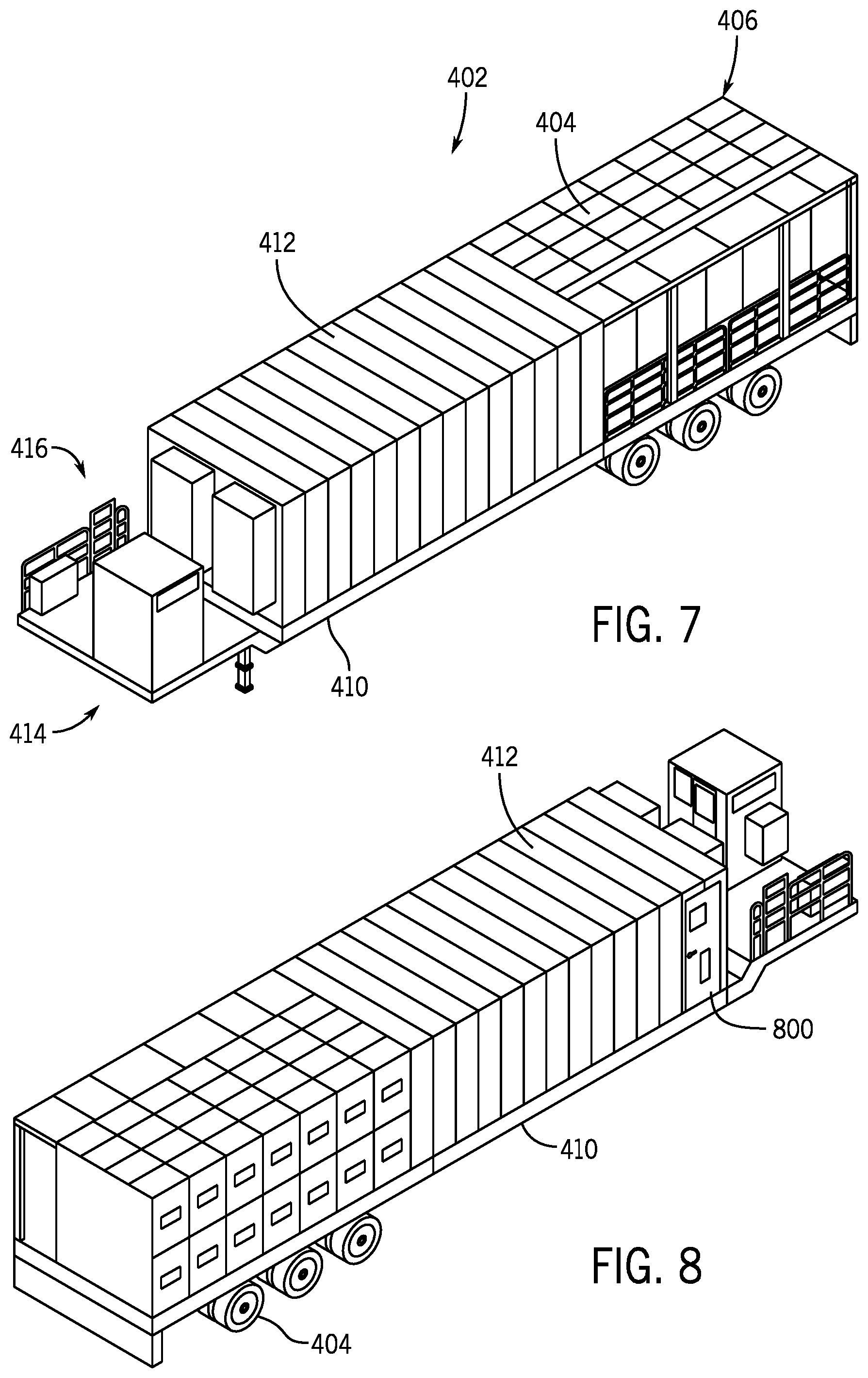
[0079] FIG. 7 is a perspective view of an embodiment of a configuration 700 that includes the primary bus 404 and the secondary bus 412, each arranged at different platforms or segments along the trailer 402. As shown, the tongue section 414 is arranged at the front 416 and includes various support components. The primary bus 404 is positioned near the rear 406 and includes the walkway 408 having an overhang, for example, to enable an operator to work out of the elements and/or protected from rain, sun, etc. Further illustrated is the enclosure 410 housing the secondary bus 412.
[0080] FIG. 8 is a rear perspective view of the configuration 700, further illustrating a door 800 for entry into the enclosure 410. In various embodiments, the power cables would extend from the primary bus 404 feeders to the incoming mains on the switchgear through the center of the substructure, which is mounted below the enclosure 410 and not visible in the illustrated embodiment.
[0081] FIGS. 9 and 10 are side elevational views of the configuration 700, further illustrating the features of the primary bus 404, enclosure 410, and the like. Illustrated in FIGS. 9 and 10 is a feed connection bulkhead area 900. As will be appreciated, these connections may be utilized to connect to equipment at the well site and may be arranged at ground level to simplify access for operators at the site. The side views of FIGS. 9 and 10 further illustrate cable access areas 902, under the primary bus 404, which may receive cables from the one or more generators.
[0082] FIG. 11 is a top plan view of the configuration 700 illustrating the corresponding locations of the primary bus 404, enclosure 410, and the tongue section 414. The configuration shown in FIG. 11 shares one or more similarities with FIG. 4 regarding the layout of the components.
[0083] FIGS. 12 and 13 are perspective views of the enclosure 410 including the secondary bus 412 where certain features have been removed to provide access to the interior of the enclosure 410. As shown, the secondary bus 412 includes a lineup that provides space for access and movement by an operator within the enclosure 410.
[0084] FIG. 14 is a schematic diagram of an embodiment of a multi-bus power distribution switchgear system 1400. The illustrated embodiment incorporates using multiple bus sections 1402, 1404 that are rated for different amperage to allow for different breaker configurations to achieve a specific size, capability, and/or price. The bus connectors (BC) 1406 are between the different bus sections 1402, 1404 and may be configured to meet NEC code for bus bar and cable protection. The illustrated embodiment only shows two main breakers, two bus connectors, and four feeder breakers for simplicity. However, as described above, in various embodiments, up to 3 main breakers, 4 bus connectors, and 24 feeder breakers may be used.
[0085] FIG. 15 is a top plan view of an oversized switchgear trailer. A different style feeder breaker is used, when compared to other embodiments illustrated herein, which is slightly larger but is compatible with a 2000 A bus and can be stacked. The main breakers can have a switch which can be used by technicians to verify that there is a visible disconnect a to the prior embodiment). The overall length and width of this trailer is greatly reduced when compared to other configurations discussed herein.
[0086] FIG. 16 is a schematic diagram of a consolidated trailer 1600. In various embodiments, the consolidated switchgear trailer may be utilized on a single bus power distribution system. A single continuous 3000 A or 2000 A bus would load share power from the incoming (main) breakers and distribute to the outgoing (feeder) breakers to the frac equipment. Because these breakers are compatible with the higher amperage bus work, they are physically larger and more expensive than breakers designed for a 1200 A bus. However, interconnecting bus connectors (as breakers, fuses, and/or switches) to safely distribute power between differently rated bus sections are no longer needed which can offset the physical size and cost increase.
[0087] FIG. 17 is a schematic diagram of an embodiment of a single bus power distribution switchgear system 1700. In the illustrated embodiment, as compared to the previous embodiments, only a single common bus 1702 is used. The Single Bus Power Distribution Switchgear System allows bus connectors and different bus sections to be eliminated. However, each breaker is configured to be compatible with the higher amperage bus and can, therefore, utilize larger and more expensive gear.
[0088] FIG. 18 is a schematic diagram of an embodiment of a load sharing configuration 1800. The illustrated embodiment may effectively load share nearly 3000 A of current on a single 2000 A common bus 1802. If the incoming power is physically entering the bus work in the middle, and the breakers to either side of the bus work can only ever draw a maximum of less than 2000 A, a 2000 A bus will be acceptable. In the example above, two main breakers 1804 are supplying up to 1400 A (IM) each for a maximum of 2800 A. If there are 12 feeders 1806 each. capable of drawing up to 150 A (IF) on each on either side of the bus work 1802, there would only be a maximum of 1800 A (IB) of current flowing outward from the main breaker connections onto the bus work 1802. In FIG. 18, for simplicity, IM=Main Breaker Current, IB=Bus Current, ID=Differential Current, IF=Feeder Current. The differential current is the maximum current that could flow between the two main breakers. This is the load sharing where the common bus 1802 will allow current from either main breaker (generators) to power either side of the bus work (frac equipment).
[0089] It should be appreciated that embodiments of the present disclosure may be utilized to power any electrical equipment, which may include as non-limiting examples: drilling rigs, coil tubing units, nitrogen, acid pump, hydraulic fracturing pumps, dual pumpers, pump down pumps, blenders, hydration units, sand equipment, dust mitigation equipment, work over rigs, auxiliary equipment, wire line trailers, cranes, and a variety of other oilfield equipment. Furthermore embodiments may also be used for microgrids in other industries beyond the oilfield. Additionally, the single switchgear can be utilized with other equipment to send power long distances including up to 3 miles or more. In embodiments, different power sources can be used including diesel generators, grid power, turbine generators, natural gas generators, battery banks, and other power sources. It should be appreciated that one or more power sources may be utilized.
[0090] The present disclosure described herein, therefore, is well adapted to carry out the objects and attain the ends and advantages mentioned, as well as others inherent therein. While a presently preferred embodiment of the disclosure has been given for purposes of disclosure, numerous changes exist in the details of procedures for accomplishing the desired results. These and other similar modifications will readily suggest themselves to those skilled in the art, and are intended to be encompassed within the spirit of the present disclosure disclosed herein and the scope of the appended claims.
* * * * *
D00000
D00001
D00002
D00003
D00004
D00005
D00006
D00007
D00008
D00009
D00010
D00011
D00012

D00013

XML
uspto.report is an independent third-party trademark research tool that is not affiliated, endorsed, or sponsored by the United States Patent and Trademark Office (USPTO) or any other governmental organization. The information provided by uspto.report is based on publicly available data at the time of writing and is intended for informational purposes only.
While we strive to provide accurate and up-to-date information, we do not guarantee the accuracy, completeness, reliability, or suitability of the information displayed on this site. The use of this site is at your own risk. Any reliance you place on such information is therefore strictly at your own risk.
All official trademark data, including owner information, should be verified by visiting the official USPTO website at www.uspto.gov. This site is not intended to replace professional legal advice and should not be used as a substitute for consulting with a legal professional who is knowledgeable about trademark law.