Method For Retrofitting A Building Using A Lift System And Component Kit For Performing The Method
GRESCHBACH; Manfred
U.S. patent application number 16/824808 was filed with the patent office on 2020-09-24 for method for retrofitting a building using a lift system and component kit for performing the method. The applicant listed for this patent is Manfred GRESCHBACH. Invention is credited to Manfred GRESCHBACH.
| Application Number | 20200299982 16/824808 |
| Document ID | / |
| Family ID | 1000004870762 |
| Filed Date | 2020-09-24 |


View All Diagrams
| United States Patent Application | 20200299982 |
| Kind Code | A1 |
| GRESCHBACH; Manfred | September 24, 2020 |
METHOD FOR RETROFITTING A BUILDING USING A LIFT SYSTEM AND COMPONENT KIT FOR PERFORMING THE METHOD
Abstract
A method for retrofitting a building using a lift system and a component kit for performing the method are provided. The shaft of the lift system extends over at least two stories 3 and comprises a self-supporting sheet metal box made of at least one steel plate, which is provided for receiving a cabin of the lift system together with its guides and drive devices. The sheet metal box of the shaft has a profiled cross section, which forms a cross-sectional area in the cross-sectional plane within the sheet metal box, which essentially covers the area required by the cabin and its guides and drive devices, and additionally contains the area of a lift platform for bridging a distance between the cabin and the building. The method provides prefabricating the lift system and installing it to the building.
| Inventors: | GRESCHBACH; Manfred; (Herbolzheim, DE) | ||||||||||
| Applicant: |
|
||||||||||
|---|---|---|---|---|---|---|---|---|---|---|---|
| Family ID: | 1000004870762 | ||||||||||
| Appl. No.: | 16/824808 | ||||||||||
| Filed: | March 20, 2020 |
| Current U.S. Class: | 1/1 |
| Current CPC Class: | E04G 23/0266 20130101; E04F 17/005 20130101; E04F 11/02 20130101; E04B 1/34 20130101 |
| International Class: | E04G 23/02 20060101 E04G023/02; E04F 17/00 20060101 E04F017/00; E04F 11/02 20060101 E04F011/02; E04B 1/34 20060101 E04B001/34 |
Foreign Application Data
| Date | Code | Application Number |
|---|---|---|
| Mar 20, 2019 | DE | 102019107165.8 |
Claims
1. A method for retrofitting a building with a lift system, the building containing a plurality of stories (3) which are subdivided and have story doors (4) which are accessible via a common staircase (5), the staircase (5) being adjacent to a front side (1) of the building and, for each story (3), having a main landing (7) for the story doors (4) and an intermediate landing (8) for a double-flight of stairs (9), the method comprising: prefabricating the lift system (26) having a shaft (27), having a cabin (36) which is movable in a longitudinal direction of the shaft (27), with guides and drive elements, and a lift platform (35) for bridging a distance between the cabin (36) and the building for each story (3), the shaft (27) extending over at least two stories (3) and comprising a self-supporting sheet metal box made of at least one steel plate, which is provided for receiving the cabin (36) together with the guides and the drive elements, said sheet metal box extends in a straight line in the longitudinal direction of the shaft (27) while being profiled in a cross-sectional plane orthogonal to the longitudinal direction of the shaft (27), and the sheet metal box of the shaft (27) having a cross section which forms a cross-sectional area in the cross-sectional plane within the sheet metal box, the cross-sectional area containing an area required by the cabin (36) and the guides and the drive elements and additionally an area of the lift platform (35), fabricating a foundation (14) for the lift system (26) in front of the front side (1) of the building, opening the front side (1) of the building in a width direction of the staircase (5), removing the intermediate landings (8) and the double-flight of stairs (9), installing walkways (24) at a height of the main landings (7), which extend horizontally from the main landings (7) to the front side (1) of the building and thereby only partially cover the cross section of the staircase (5) to provide clear space for a flight of stairs, installing a single-flight of stairs (22) which connects the individual walkways (24) to one another and forms a modified staircase therewith, setting up the lift system (26) on the foundation (14), aligning the lift system (26) on the foundation (14) and joining the lift system (26) to the front side (1) of the building, establishing a connection between the lift platforms (35) and the walkways (24) on each story (3), and establishing access to the lift platform (35) of the ground floor from outside the building.
2. The method as claimed in claim 1, wherein the installation of the walkways (24) and the installation of the single-flight of stairs (22) is carried out by installing a preassembled staircase module (19) which contains at least the walkways (24) and stair sections (23) which connect the walkways (24) over one flight, and a holding structure (25) to which the walkways (24) and the stair sections (23) are fastened.
3. The method as claimed in claim 2, wherein the holding structure (25) is formed of a number of interconnected profiles or tubes, running in a stairwell or between the walkways (24) and the stair sections (23) and connecting all of the walkways (24) to one another.
4. The method as claimed in claim 3, further comprising before the installation of the staircase module (19), installing a basement staircase module (16) having a single-flight stair section (23) and supports (17) for the staircase module (19).
5. The method as claimed in claim 4, further comprising before the installation of the staircase module (19), attaching auxiliary rails (18) for sliding the staircase module (19) into the building, and sliding the staircase module (19) in using the auxiliary rails (18) through the open front side (1) of the building.
6. The method as claimed in claim 1, further comprising sealing contact points between the lift system (26) and the front side (1) of the building using at least one of assembly foam or an elastomeric sealing element.
7. The method as claimed in claim 1, wherein the foundation is fabricated as a foundation plate (14) from a one-part or multi-part precast concrete part (13).
8. The method as claimed in claim 1, further comprising using straight stair sections (23) having at least one of a quarter-turn entrance or exit or having a quarter platform at at least one of the entrance or exit for the single-flight of stairs (22).
9. The method as claimed in claim 1, further comprising using the shaft (27) for the lift system (26) to establish access to the lift platform (35) of the ground floor from outside the building, the sheet metal box of which, in a position in which the lift platform (35) for the ground floor of the building is located after the lift system (26) has been attached to the building on a side that is not a building side of the shaft (27), is provided with a passage opening for a front door (29), and attaching an outer staircase (32) to the shaft (27) which connects the passage opening of the shaft (27) to the ground level (2).
10. The method as claimed in claim 1, further comprising, before the installation of the walkways (24), in each case using a crossbeam, which is fastened on both sides of the staircase (5) to the outer walls of the front side (1) of the building, and placing the respective walkway (24) on the crossbeam.
11. A component kit for performing the method as claimed in claim 1, comprising: the shaft (27) for the lift system and the preassembled staircase module (19), the staircase module (19) including a walkway (24) for each story (3) and the stair sections (23) which connect the walkways (24) over a single flight, and a holding structure (25) to which the walkways (24) and the stair sections (23) are fastened, and the shaft (27) extending over at least two of the stories (3) and comprising the self-supporting sheet metal box made of the at least one steel plate for receiving the cabin (36) together with the guides and drive elements, the sheet metal box extending in a straight line in the longitudinal direction of the shaft (27), and being profiled in the cross-sectional plane orthogonal to the longitudinal direction of the shaft (27), and the sheet metal box of the shaft (27) having the cross section forming the cross-sectional area within the sheet metal box in the cross section plane, the cross-sectional area containing the area required by the cabin (36) and the guides and drive elements and additionally the area of the lift platform (35).
12. The component kit as claimed in claim 11, wherein the holding structure (25) includes a number of interconnected profiles or tubes which extend in the stairwell or between the walkways (24) and the stair sections (23) and connecting all of the walkways (24) to one another.
13. The component kit as claimed in claim 11, wherein the stair sections (23) include at least one of quarter-turn entrance or exits or having a quarter platform at at least one of the entrance or exit.
14. The component kit as claimed in claim 11, further comprising a foundation plate (14) made of a one-part or multi-part precast concrete part (13).
15. The component kit as claimed in claim 11, further comprising a basement staircase module (16) having a single-flight stair section (23) and supports (17) for the staircase module (19).
16. The component kit as claimed in claim 11, wherein the shaft (27) comprises the sheet metal box and the lift platform (35) for each said story (3).
17. The component kit as claimed in claim 11, wherein the lift platforms (35) are provided with anchoring devices for anchoring to elements of the staircase (5) of the building.
18. The component kit as claimed in claim 11, wherein the sheet metal box is open on a building side of the shaft (27).
19. The component kit as claimed in claim 11, wherein the sheet metal box is provided with light openings (28) in a wall adjacent to the lift platforms (35).
Description
INCORPORATION BY REFERENCE
[0001] The following documents are incorporated herein by reference as if fully set forth: German Patent Application No. DE 10 2019 107 165.8, filed Mar. 20, 2019.
TECHNICAL FIELD
[0002] The present invention relates to a method for retrofitting a building using a lift system having a prefabricated shaft, and a component kit for performing the method.
BACKGROUND
[0003] The prefabricated shaft extends over at least two stories and comprises a self-supporting sheet metal box, which is provided for receiving a cabin of the lift system together with its guides and drive devices, which may also contain a counterweight. The at least one steel plate that forms the self-supporting sheet metal box runs in a straight line in a longitudinal direction of the shaft, which corresponds to the direction of movement of the cabin, while it is profiled in a cross-sectional plane that is orthogonal to the longitudinal direction of the shaft. Such a prefabricated shaft is known from EP 3 315 448 A2.
[0004] Traditionally, lift shafts consist of a concrete or steel structure that is erected on site at the construction site. After the lift shaft has been erected, the assembly of the actual lift system is generally carried out on site by installing a cabin, its suspension and drive, and all the components required for operation. This results in a total construction time of several weeks. This is particularly disadvantageous when the lift system is used to retrofit an existing and used building; that is because access to the building is difficult during the construction phase.
[0005] A solution to this problem has already been disclosed in BE 568 738. It was proposed therein to manufacture the shaft of the lift system from a plurality of thin-walled steel plates which abut one another at the corners of the generally rectangular shaft and are connected to one another and stabilized there by means of profiles, angle irons and the like. This made it possible to prefabricate the shaft as a sheet metal box and even to install the cabin, its guides and drive devices in the shaft in the factory and only then to transport it to the construction site. The assembly time of the lift system could be greatly reduced due to the high degree of prefabrication.
[0006] In order to improve the stability of a lift system having such a prefabricated shaft, EP 3 315 448 A2, already mentioned, proposes to fabricate the sheet metal box with which the shaft is manufactured from at least one steel plate which runs in a straight line in the longitudinal direction of the shaft, while being profiled in the cross-sectional plane; the at least one steel plate is preferably formed in one piece in the longitudinal direction over the entire extent of the shaft. This self-supporting and stable design of the sheet metal box makes it possible, on the one hand, to transport the prefabricated shaft from the factory to the construction site by means of a lorry; on the other hand, due to its inherent stability, the lift system manufactured with the self-supporting sheet metal box can be placed on an existing building without being supported on the building, so that the statics of the building remain unaffected and there is no need to recalculate said statistics.
[0007] Lift systems for attaching to a building or for retrofitting a building are generally used in older buildings, in which no barrier-free access has yet been considered. In particular, residential buildings having a plurality of residential units, which are distributed over several stories, but also administrative buildings and commercial buildings, often have a plurality of stories, which are in particular divided into a plurality of residential units or other closed units and have corresponding story doors. These story doors are usually accessible via a common staircase. A common construction of such multi-story houses integrates the staircase at the front side of the building with an entrance door at ground level and a double-flight of stairs that allows access to all story doors via main landings on each story and intermediate landings. These are located on the main landings in this construction.
[0008] It is obvious that people with disabilities in such buildings have little chance of getting to the story doors on their own. Even heavy objects usually have to be transported via the staircase and can therefore often not be made easier with the appropriate aids. It is therefore often desirable to retrofit such a multi-story building using a lift system. One of the lift systems described above having a prefabricated shaft is offered for this purpose.
[0009] A lift system for attaching to a building from the outside or a method for retrofitting a building with such a lift system is known from DE 196 33 636 A1. From this prior art, it can be seen that retrofitting the building in this way only partially solves the problem of unhindered access for people with walking difficulties. Due to the fact that when the retrofitted lift system is placed on the front side of the building in front of the staircase and the transitions between the shaft and the corresponding building openings in the front side of the building are made, a person who emerges from the lift cabin on the desired story can only reach an intermediate landing of the staircase, so they would still have to climb half a story up or down by means of a stair section of the double-flight of stairs in order to access the story doors.
[0010] If a corresponding building is to be modernized to be largely barrier-free by retrofitting a lift system, it has therefore not hitherto been the means of choice to use a prefabricated lift system or a prefabricated shaft of the type mentioned at the beginning. Instead, the staircase needs to be gutted and completely rebuilt using a lift system. Since access to the story doors is generally not possible during the corresponding construction period, one usually refrains from retrofitting a corresponding building using a lift system, at least from the point of view of the greatest possible accessibility.
SUMMARY
[0011] The present invention is therefore based on the object of providing a method for retrofitting a building using a lift system and a component kit for performing this method, with which a building having a plurality of stories and a staircase adjacent to a front side of the building and, per story, has a main landing and an intermediate landing for a double-flight of stairs, can be retrofitted at least largely barrier-free with a lift system.
[0012] This object is achieved by a method and a component kit having one or more features of the invention.
[0013] Advantageous embodiments of the method according to the invention and preferred developments of the component kit according to the invention are described below ad in the claims.
[0014] The prefabricated shaft used according to the invention for a lift system to be attached to a building from the outside enables a building to be retrofitted using a lift system largely barrier-free even if the building is accessed via a staircase having intermediate landings. For this purpose, the shaft extends over at least two stories and comprises a self-supporting sheet metal box made of at least one steel plate, which is provided for receiving a cabin of the lift system together with its guides and drive devices, that is, also a counterweight if necessary. The at least one steel plate runs in a straight line in a longitudinal direction of the shaft, which corresponds to the direction of movement of the cabin, while it is profiled in a cross-sectional plane orthogonal to the longitudinal direction of the shaft. The at least one steel plate preferably extends in one piece in the longitudinal direction of the shaft over the entire extent thereof, while two or more steel plates are joined to one another in the circumferential direction, as is known per se. According to the invention, the sheet metal box of the shaft has a cross section that goes beyond the mere enclosure of the cabin and the other components: the sheet metal box is profiled in such a way that a cross-sectional area is created in the cross-sectional plane within the sheet metal box, which cross-sectional area essentially contains the area required by the cabin and its guides and drive devices, and in addition the area of a lift platform to bridge a distance between the cabin and the building. Preferably, the prefabricated shaft is fabricated with one lift platform per story.
[0015] Such a prefabricated shaft, placed in front of the front side of the building, can cover the entire width of the staircase, so that it can be opened completely to the front side of the building when the building is retrofitted using the lift system. Since there is space within the prefabricated shaft for a lift platform that a person steps on after leaving the cabin, the cabin can be arranged at a certain distance, namely the width of the lift platform, in front of the front side of the building, which advantageously enlarges freedom of design inside the staircase.
[0016] For buildings that have a staircase having intermediate landings and the ground floor of which is half a story above ground level, it is essential to provide external access to the ground floor level after the intermediate landings have been removed without having to use the lift system. This is made possible by the concept of an additional lift platform to bridge a distance between the cabin and the building. Such external access can be created by opening access to the lift platform via an outer staircase in addition to the cabin. Without a lift platform, external access through a sheet metal box covering the entire width of the staircase on the front side of the building would only be possible if an appropriate additional platform were installed inside the staircase. However, the installation space is usually not sufficient for this. The lift platform and the correspondingly designed cross section of the sheet metal box rather increase the area of the staircase. This is also the case when the building to which the lift system is to be attached does not contain a staircase having intermediate landings, so that the prefabricated shaft used according to the invention offers advantages even then.
[0017] Using the lift platform provided according to the invention, the traffic area in front of the lift system in the staircase is expanded at the same level; thus, with the concept according to the invention, the requirements for complete barrier-free access, which, in addition to level access, also require maneuvering areas of typically 1.5 m.times.1.5 m in front of a lift door, can be met without any problems.
[0018] Since the prefabricated shaft according to the invention is intended to retrofit a building using a lift system and thereby to cover the entire area of the staircase at the front side of the building, it is preferred when the sheet metal box is provided with light openings in a wall adjacent to the lift platforms. To increase the degree of prefabrication, these light openings can already be equipped with windows when the prefabricated shaft is transported to the construction site.
[0019] When the prefabricated shaft is provided with lift platforms, these preferably have anchoring devices for anchoring to elements of the staircase, wherein these anchoring devices preferably produce a floating anchor between the lift platform and a continuing platform or walkway inside the staircase.
[0020] The sheet metal box of the prefabricated shaft is preferably essentially open on the side which, in the assembled state, faces the front side of the building. In this way, the sheet metal box enlarges the enclosed space of the staircase, and in particular the lift platforms become part of the staircase. In the area in which the cabin moves within the sheet metal box, this building side of the shaft can be provided with cross struts and sheathings, so that only one passage opening for entering and exiting the cabin remains free.
[0021] The sheet metal box of the prefabricated shaft preferably has a passage opening on one side that is not the building side, which passage opening is located in a position in which the lift platform for the ground floor of the building is located after the lift system has been attached to a building. This passage opening thus forms the front door to be made accessible via an outer staircase, through which one can get into the building or the staircase bypassing the lift system. In addition, there are advantages when a further passage opening is added on the ground level on one side of the sheet metal box, which side is not the building side of the shaft, and through which the cabin inside the shaft is accessible from the outside at ground level. This ensures barrier-free access to the lift system, even when a building is retrofitted using the prefabricated shaft according to the invention, the ground floor of which is half a story above the ground level.
[0022] The sheet metal box of the prefabricated shaft preferably has a bottom surface which is provided with fastening elements for fastening the shaft to a foundation, wherein the fastening elements advantageously have adjustment devices in order to be able to align the shaft vertically on the foundation.
[0023] For buildings whose entrance and staircase are arranged on the front, the prefabricated shaft must be set up on this front side. However, the supply lines for fresh water, waste water, electricity and information technology usually run there at a depth of typically 1.20 m below ground level. A conventional prefabricated shaft is provided with an underpass below the lowest station of the cabin, in particular to provide sufficient movement path for a counterweight of the cabin. Since the lowest station approached by the cabin should be on ground level for extensive accessibility, a correspondingly deep excavation is necessary for the foundation of the lift system to make room for this underpass. For this, however, the supply lines would have to be laid, which is associated with corresponding effort and a period in which the building cannot be used. It is therefore preferred in the context of the present invention when the sheet metal box has a shortened underpass and is extended upwards in accordance with this shortening. This enables the foundation for the lift system to be made to a depth that is still above the supply line. This depth is typically between 0.8 m and 1.0 m.
[0024] The lift system used according to the invention for attaching to a building from the outside comprises a prefabricated shaft described above, a cabin which can be moved in the longitudinal direction of the shaft, its guides and drive devices and a lift platform for each story. In order to increase the degree of prefabrication, the lift system preferably also already comprises all doors and windows and a seal for joining the shaft to the front side of the building. Due to the inherent stability of the sheet metal box used for the prefabricated shaft, the lift system according to the invention can be transported in the prefabricated state to the construction site by a lorry and set up there.
[0025] The method according to the invention for retrofitting a building using a lift system according to the invention is provided for a building that contains a plurality of stories, which are in particular subdivided and have story doors which are accessible via a common staircase. The staircase is adjacent to the front side of the building and has, per story, a main landing for the story doors and an intermediate landing for a double-flight of stairs.
[0026] According to the method according to the invention, the lift system is first prefabricated in the factory. A foundation for the lift system is fabricated in front of the front side of the building. Regardless of the time, the front side of the building is opened in the width of the staircase, the intermediate landings and the double-flight of stairs are removed, walkways are installed at the height of the main landings, which extend horizontally from the main landings to the front side of the building and thereby cover the cross section of the staircase only partially, in particular half, to leave clear space for a flight of stairs, and a single-flight of stairs that connects the individual walkways to one another and together forms a modified staircase therewith is installed. Afterwards, the prefabricated lift system, after being transported from the factory to the construction site, is set up on the foundation, aligned thereto and thereby joined to the front side of the building. A connection is made between the lift platforms and the walkways of each story, which is preferably designed to be floating in order to enable a slight relative movement between the lift system and the building. Finally, access to the lift platform of the ground floor is made from outside the building, preferably by attaching a front door to the sheet metal box of the lift shaft and fastening an outer staircase in order to be able to get from the ground level to the front door.
[0027] Using the method according to the invention, it is possible for the first time to retrofit an existing and used building within a few working days, typically three to four days, with a lift system, largely barrier-free, and then to free up the building again completely for unrestricted use. Due to the high degree of prefabrication of the lift system, the operational safety tests and approvals are limited to an acceptance test of the installed lift system on site, which can typically be done within a day.
[0028] According to a preferred embodiment of the method according to the invention, the contact points between the lift system and the front side of the building are sealed, in particular using assembly foam and/or an elastomeric sealing element. This can be, for example, a U-profile or a hose that is filled with fire protection foam.
[0029] To fabricate the foundation for the lift system in front of the front side of the building, an excavation for a shallow foundation is preferably made, in particular with a case bottom of approx. 0.8 m to 1.0 m depth, so as not to impair any supply lines that are typically laid at a depth of approx. 1.2 m.
[0030] The foundation itself is preferably prepared as a foundation plate from a one-part or multi-part precast concrete part. This has the advantage that the foundation plate does not have to be concreted on site, but can be delivered in a completed state by lorry. For this purpose, the foundation plate can be formed in several parts, wherein each precast concrete part that is to become part of the foundation plate has dimensions and a weight with which transport on a normal lorry is possible.
[0031] The foundation plate is preferably made from two precast concrete parts which are initially not connected to one another. Only after the lift system has been set up on the foundation are the two precast concrete parts indirectly fastened to one another, in that the shaft of the lift system is partly fixed to the first and partly to the second precast concrete part.
[0032] For the single-flight of stairs that connects the individual walkways to one another and forms a modified staircase therewith, straight stair sections having a quarter-turn entrance and exit, or having a quarter platform at the entrance and exit, are preferably used. This shape of the stair sections makes the intermediate landings superfluous; the main landings are also preferably not part of the flight of stairs, rather only the walkways connect the individual stair sections on the way up or down. This can be very advantageous, in particular with regard to complete barrier-free access to the staircase, because the main landings are preserved as mere maneuvering areas.
[0033] In an alternative embodiment, straight stair sections having only a quarter-turn entrance or exit can be used, wherein the stair sections, depending on the orientation of their slope, begin or end on the main landing or use the main landing as a quarter platform of the flight of stairs.
[0034] According to the invention, two alternatives are provided for installing the walkways and the single-flight of stairs to replace the removed intermediate landings and the double-flight of stairs:
[0035] According to a first alternative, a crossbeam is used before installing the walkways, which crossbeam is fastened on both sides of the staircase to the outer walls of the front side of the building, and on which the respective walkway is placed. Here, the removal of the intermediate landings and the double-flight of stairs and the installation of the walkways and the single-flight of stairs are carried out in successive partial sections from top to bottom, for example, using a lifting platform.
[0036] According to a second alternative, the walkways and the single-flight of stairs are installed by installing a preassembled staircase module. The procedure is therefore not successive, but rather the staircase is first gutted by removing the intermediate landings and the double-flight of stairs in order to be able to use the staircase module in one piece. The staircase module in this case contains at least the walkways and the stair sections which connect the walkways over a single-flight and preferably have a quarter-turn entrance and/or exit. In addition, the staircase module contains, as an essential element, a holding structure to which the walkways and the stair sections are fastened and which preferably consists essentially of a number of interconnected profiles or tubes which run in the stairwell and connect all walkways to one another.
[0037] To simplify the installation of the staircase module, a separate basement staircase module is preferably used, which comprises a single-flight stair section and support for the staircase module, and which is installed before the staircase module is installed by inserting it into the gutted staircase and is set up there on the basement floor.
[0038] The installation of the staircase module is particularly easy when, in addition, auxiliary rails for sliding in the staircase module into the building are installed on the ground level and the staircase module can be slid in through the open front side of the building by means of the auxiliary rails. The foundation for the lift system is expediently covered before the auxiliary rails are attached, in order to avoid any damage to the foundation. After the staircase module has been slid in, the auxiliary rails can be removed or cut to length, and the staircase module essentially rests on the supports of the basement staircase module. In addition, the walkways of the staircase module can be connected to building walls and/or the main landings. Such a staircase module in turn increases the degree of prefabrication when retrofitting a building using a lift system, whereby the construction time for the retrofitting is shortened again.
[0039] Finally, the present invention also comprises a component kit for performing the method according to the invention, wherein this component kit comprises at least one prefabricated shaft according to the invention and a preassembled staircase module, wherein the staircase module consists of one walkway for each story and of stair sections which connect the walkways over a single flight, and a holding structure to which at least the walkways and preferably also the stair sections are fastened.
[0040] The holding structure of the preassembled staircase module preferably consists essentially of a number of interconnected profiles or tubes which run in the stairwell and connect all the walkways to one another.
[0041] The stair sections of the preassembled staircase module are preferably designed as stair sections having a quarter-turn entrance and/or exit or having a quarter platform at the entrance and/or exit.
[0042] The component kit according to the invention can also comprise a foundation plate made of a one-part or multi-part precast concrete part, and a separate basement staircase module having a single-flight stair section and supports for the staircase module.
BRIEF DESCRIPTION OF THE DRAWINGS
[0043] An embodiment of a lift system designed according to the invention and an embodiment for performing a method according to the invention are described and explained in more detail with reference to the accompanying drawings. Shown are:
[0044] FIGS. 1 to 20 different phases in the performance of an embodiment for a method according to the invention, in a schematic representation;
[0045] FIG. 21 a lateral cross section through a staircase of a building from FIGS. 1 to 20, using a retrofitted lift system;
[0046] FIGS. 22A-22C three sections with views of the staircase from FIG. 21 from above, namely through the basement, through the ground floor and through an upper story;
[0047] FIG. 23 a cross section through the lower half of the staircase, according to another embodiment;
[0048] FIG. 24 a part of a lateral cross section as in FIG. 21, but according to another embodiment; and
[0049] FIG. 25 a section having a view from above as in FIG. 22C, but according to the embodiment from FIG. 24.
DETAILED DESCRIPTION
[0050] The method shown schematically illustrated in FIGS. 1 to 20 in selected method steps and designed according to the invention is an example of the retrofitting according to the invention of a used residential building using a lift system according to the invention, which can be carried out on site within three working days.
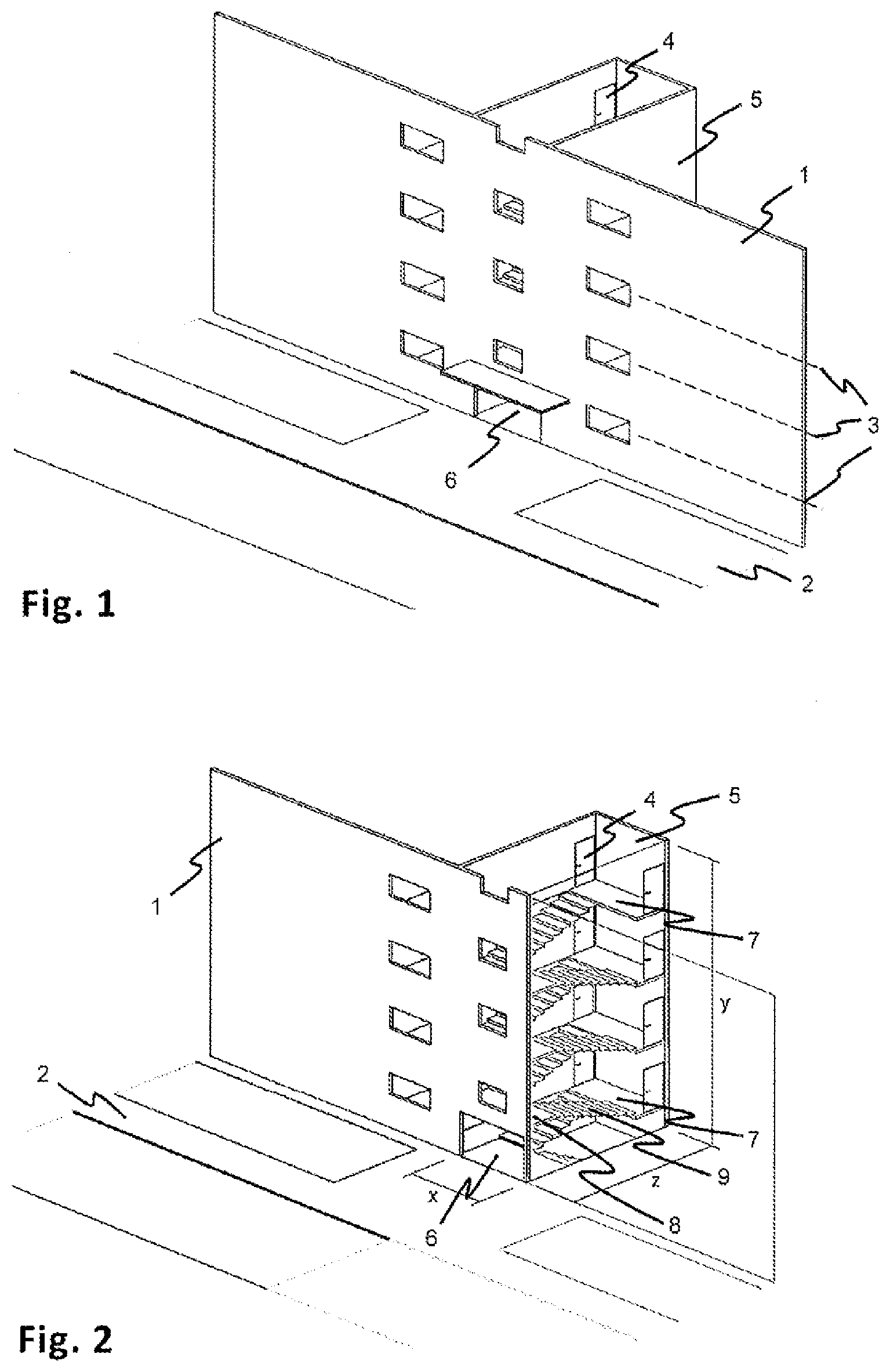
[0051] FIG. 1 shows schematically a front side 1 of a four-story building, the ground floor of which is half a story height above ground level 2. A total of eight flats are accommodated in the four stories 3 above ground level 2, which flats are accessible via story doors 4. These make the flats accessible via a central staircase 5, which is adjacent to the front side 1 of the building and can be entered from the outside via a front entrance 6.
[0052] FIG. 2 shows the staircase 5 in greater detail. It is thus clear that the staircase 5 contains, in addition to eight story doors 4 for each story, a main landing 7, which is associated with the story doors 4, and an intermediate landing 8 for two flights of stairs 9. It is also clear here that the front entrance 6, which is located on ground level 2, leads to an intermediate landing for the double-flight of stairs 9, so that access to the ground floor can only be reached via a stair section of the double-flight of stairs.
[0053] FIG. 3 symbolizes the pick-up of residents who move to a hotel for the three-day construction work.
[0054] FIG. 4 shows that the construction work begins with an excavation 10 for a shallow foundation of the lift system (not yet illustrated here) and in parallel with a cut 11 for opening the front side 1 of the building in the width of the staircase 5.
[0055] In order to protect any supply lines of the building for fresh water, waste water, electricity and/or data traffic against excessive loads, as shown in FIG. 5, a specific cover 12 can be attached in the excavation 10. The excavation 10 is typically 0.8 m to 1.0 m deep, so that the supply lines can remain in place.
[0056] FIG. 6 symbolizes the delivery and insertion of a first precast concrete part 13 as part of a foundation plate 14 into the excavation 10, while the opening of the front side 1 of the building proceeds.
[0057] In FIG. 7, a second precast concrete part 13' has been delivered and inserted into the excavation 10, so that the foundation plate 14 has already been completed.
[0058] As FIG. 8 shows, the foundation plate 14 is then protected by placing a foundation cover 15 for the further construction work.
[0059] FIG. 9 illustrates schematically that after opening the front side 1 of the building, the double-flight of stairs 9 and the intermediate landings 8 are removed from the staircase 5. The main landings 7, however, remain in place.
[0060] As FIG. 10 shows, a basement staircase module 16 is then introduced into the staircase 5 and placed on the floor of the basement. This basement staircase module 16 essentially consists of a stair section 23 and a support 17 for setting up a staircase module (not yet illustrated here).
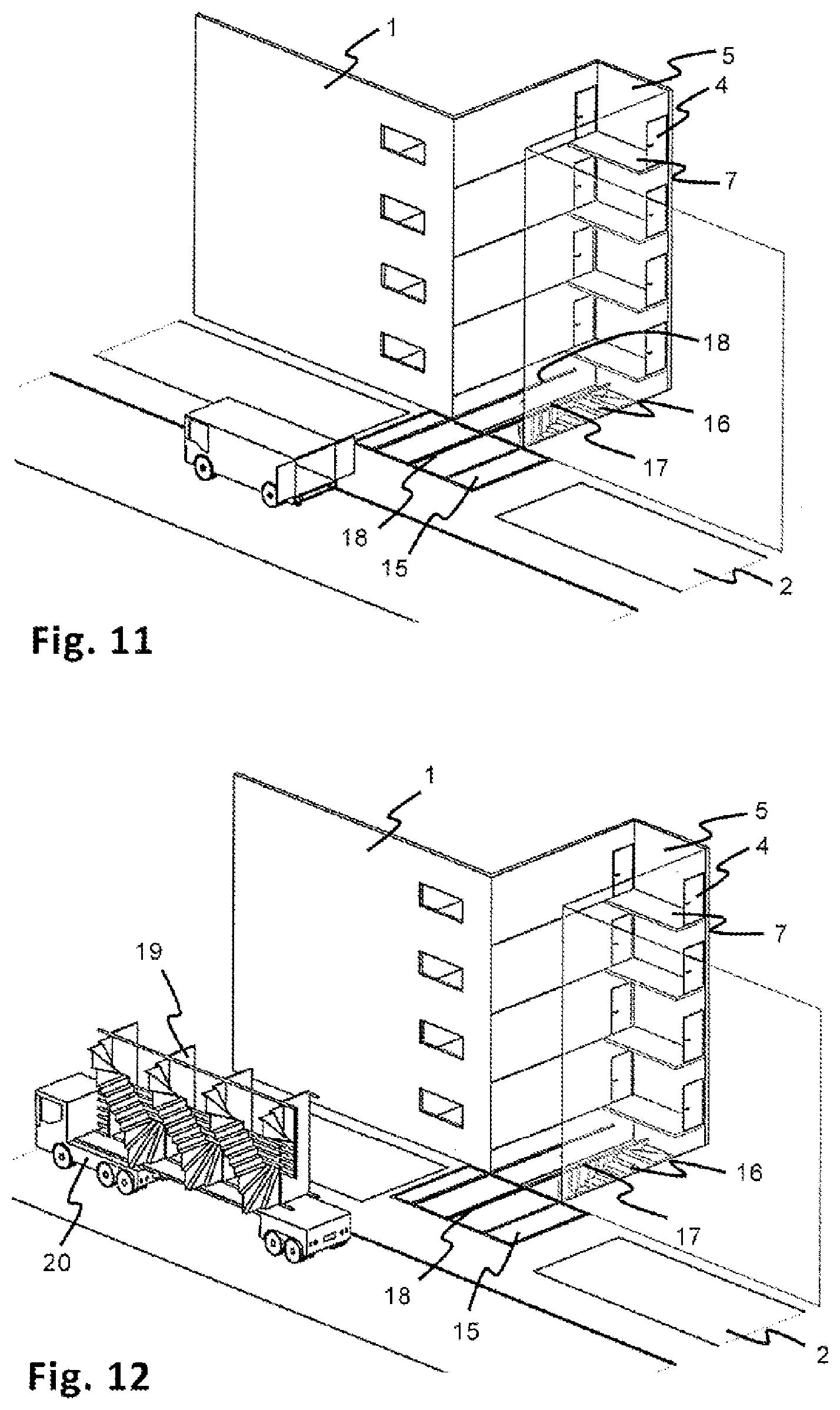
[0061] FIG. 11 illustrates how three auxiliary rails 18 are introduced into the staircase 5 on ground level 2, namely one auxiliary rail 18 each on the side walls of the staircase 5 and a third auxiliary rail 18 on the support 17 of the basement staircase module 16. The auxiliary rails 18 run over the foundation cover 15 here.
[0062] As shown in FIGS. 12, 13 and 14, a staircase module 19, which was prefabricated in the factory and can be delivered using a lorry 20 due to a corresponding inherent stability, is then lifted from the lorry 20 by a crane lorry 21, placed on the auxiliary rails 18 and slid into the staircase 5 along the auxiliary rails 18. The staircase module 19 here consists of a single-flight of stairs 22 having individual stair sections 23, each of which has a quarter-turn entrance and exit, in order to connect a walkway 24 for each story to the walkway 24' located below or above it. In particular, FIG. 15 illustrates here that the quarter-turn stair sections 23 continue to maintain the main landings 7 with regard to desirable barrier-free accessibility as maneuvering areas; the same applies to the lift platforms 35 (not shown here) (see FIGS. 21 to 23).
[0063] The staircase module 19 obtains the necessary inherent stability through a holding structure 25 which is arranged in the stairwell and comprises a plurality of vertically running steel tubes which connect the individual walkways 24, 24' to one another and finally transfer the load onto the support 17 of the basement staircase module 16.
[0064] After making connections between the walkways 24 and the main landings 7, and optionally after additional securing of the walkways 24 and/or the stair sections 23 on the side walls of the staircase 5, the foundation cover 15 is removed again and the auxiliary rails are scaled back by cutting to length. FIG. 15 shows this state.
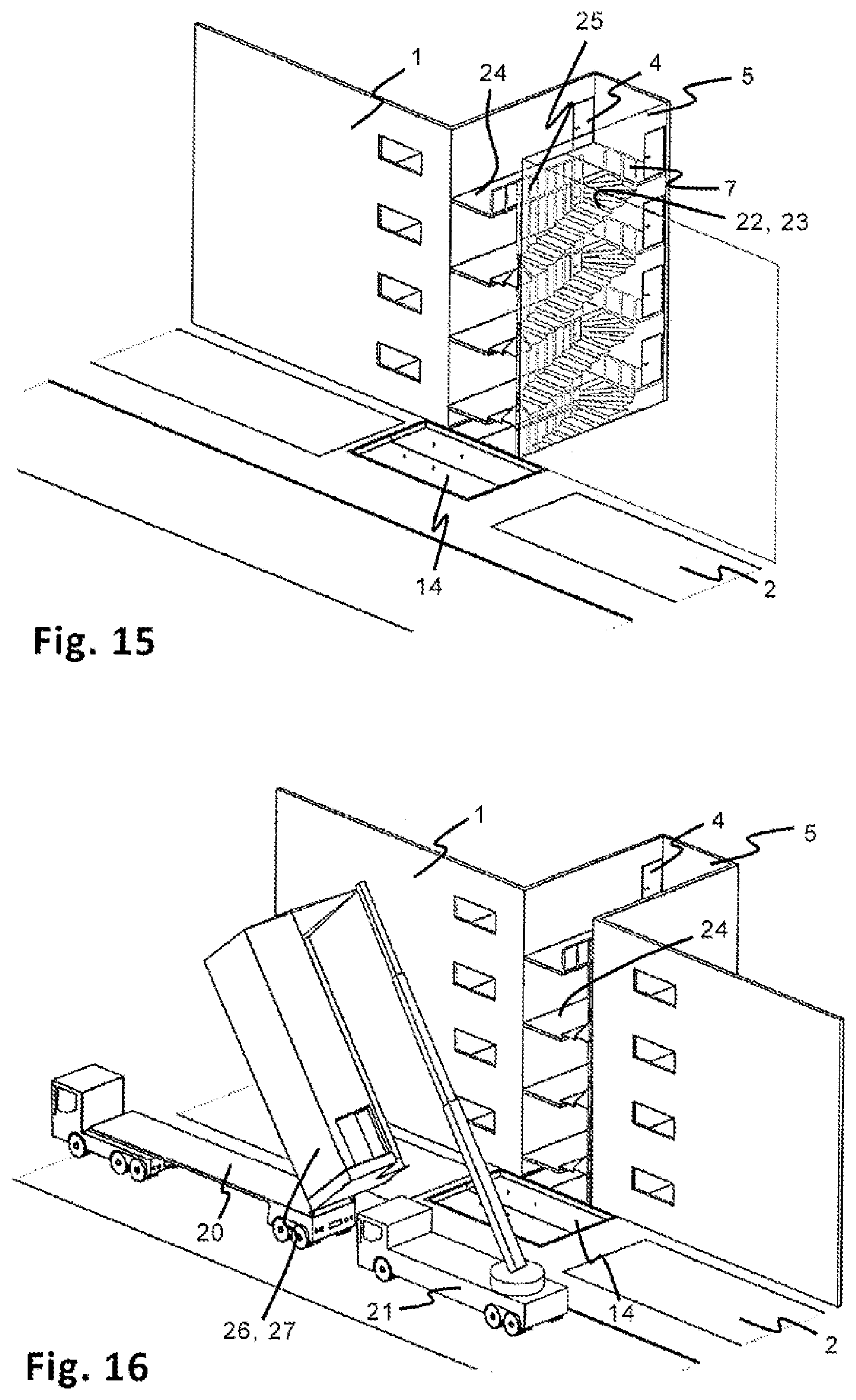
[0065] The construction site is thus prepared for the delivery of a lift system 26 designed according to the invention, which in turn is delivered using a lorry 20 and is lifted and set up by a crane lorry 21, as shown in FIGS. 16 and 17. The lift system 26 here consists of a prefabricated shaft 27 designed according to the invention, in which a (not visible here) cabin is installed together with its guides and drive devices and other devices necessary for operation. The shaft 27 also comprises lift platforms (not visible here) for each story and a number of light openings 28 with windows, a front door 29 and a ground-level passage opening 30 positioned on ground level 2 for operating the cabin guided in the shaft 27.
[0066] As FIG. 17 shows, the lift system 26 is set up on the foundation plate 14 and then aligned and fixed. At the same time, the contact surfaces between the shaft 27 and the front side 1 of the building are sealed with fire protection foam. As can be seen from FIG. 17, the shaft 27 covers the entire width of the staircase 5, so that the front side 1 of the building is closed again after the lift system 26 has been set up.
[0067] In order to create an escape route or access to the staircase 5 and to the individual story doors 4 bypassing the lift, the front door 29, which is now located at the level of the ground floor, since it leads to the ground floor lift platform, from where the ground floor walkway 24 and the ground floor main landing 7 can be reached, is equipped with an outer platform 31 and an outer staircase 32.
[0068] After removal of the lift system 26 and attachment of handrails 33 and a canopy 34, as shown in FIG. 19, the retrofitting of the building with the lift system 26 is completed and, as shown in FIG. 20, the residents can move into their flats again.
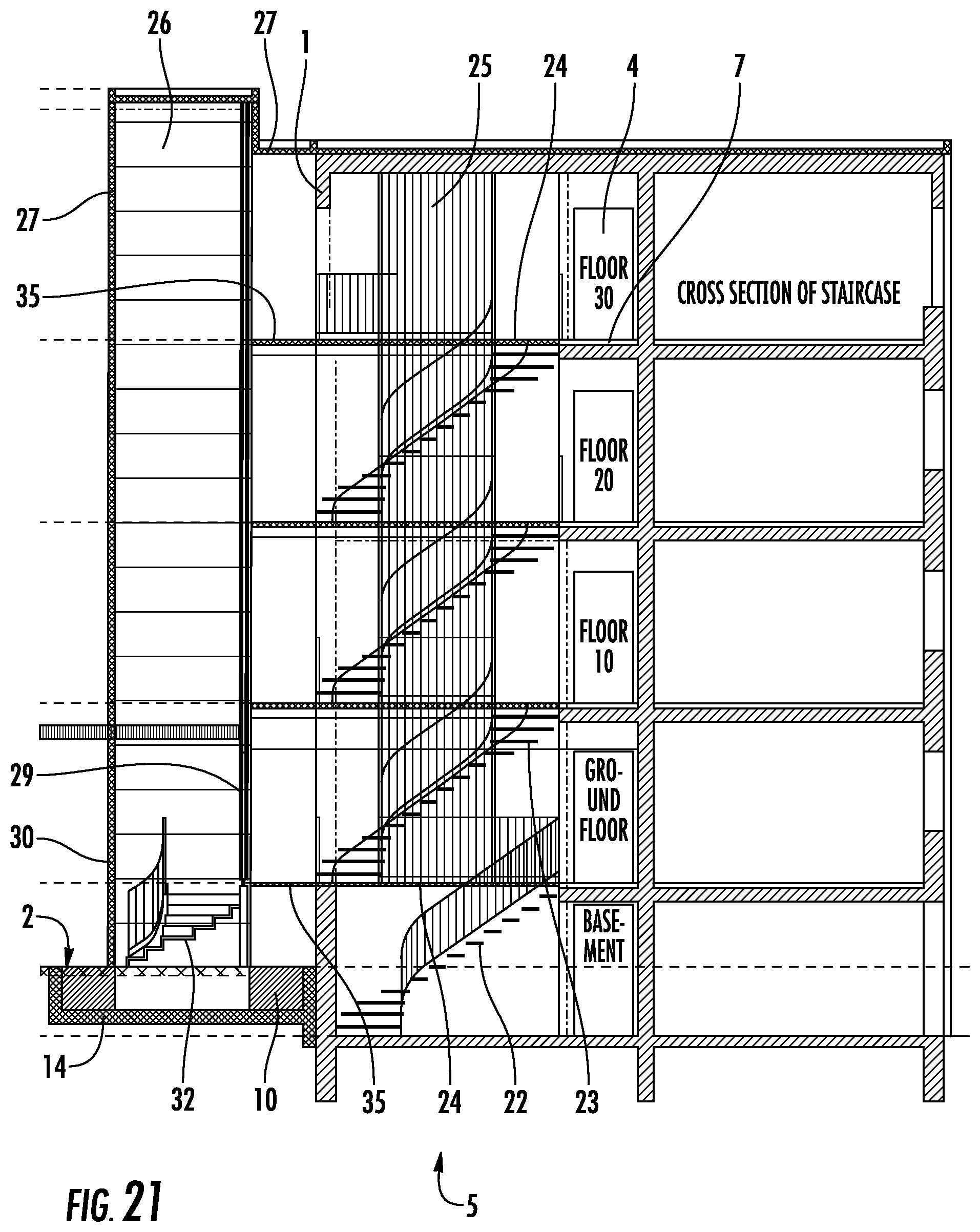
[0069] FIG. 21 illustrates the result of an embodiment of a method according to the invention in a lateral sectional illustration through the staircase 5. The associated FIGS. 22A-22C show sectional views from above through the basement (FIG. 22A), through the ground floor (FIG. 22B) and through one of the upper stories (FIG. 22C), which in particular illustrates the construction according to the invention of the lift system 26 or the prefabricated shaft 27.
[0070] As FIG. 21 shows, the staircase 5 consists of four above-ground stories, a ground floor and three upper stories, and a basement. The story doors 4 each open onto a main landing 7 which has remained in its original state. The front side 1 of the building has been opened, and the main landings 7 have been connected at the same level to lift platforms 35 by means of inserted walkways 24 fastened to the staircase side walls, which were joined together with the prefabricated shaft 27 to the front side 1 of the building. The shaft 27 stands here on a foundation plate 14, which was previously inserted in front of the front side 1 of the building in a corresponding excavation 10.
[0071] At ground level 2, an outwardly oriented passage opening 30 can be reached in the shaft 27, through which a cabin (not illustrated here) that is movable within the shaft 27 in the longitudinal direction is accessible. Alternatively, access to the staircase 5 via the outer staircase 32 and the front door 29 to the ground floor lift platform 35 is ensured, from where the single-flight of stairs 22 with the walkways 24 can be reached without having to use the lift system 26.
[0072] As FIG. 21 illustrates, each level of each main landing 7 or each story door 4 can be reached directly via the lift system 26, and each story door 4 can be reached by the lift system 26 at the same level via the lift platform 35, the walkway 24 and the main landing 7 without any barriers.
[0073] The stair sections 23 having quarter-turn entrance and exit prevent the main landings 7 and the lift platforms 35 from having to be part of the single-flight of stairs 22. Rather, they can be used as mere traffic and maneuvering areas in the sense of complete accessibility. Appropriate handrails ensure the necessary traffic safety.
[0074] The central function of the lift platform 35 is illustrated using FIG. 22, in particular FIG. 22B. This is the only way to ensure an escape route or access to the staircase 5 without having to use the lift system 26. Due to the fact that since the ground floor, which is half a story above ground level 2, can only be reached at the same level from the front side 1 of the building via a walkway 24, an outer staircase 32 must be provided, via which one can get from ground level 2 to walkway 24. If the cabin 36 of the lift system 26 were not spaced apart from the front side 1 of the building, as is the case here, but rather opened directly towards the walkway 24, it would not be possible to access the walkway 24 via the outer staircase 32. At the same time, the lift platform 35 increases the area of the staircase 5 since the shaft 27 with its lift platform 35 covers the entire width of the staircase 5 and thereby closes the front side 1 of the building again.
[0075] FIG. 22A moreover again illustrates that the foundation plate 24 is composed of two precast concrete parts 13, which are indirectly connected to one another by fastening each precast concrete part 13, 13' to the lift system 26. The stair section 36, which leads from the basement to the ground floor, has a quarter-turn entrance, but a straight exit, since it is part of the basement staircase module 16, which ultimately forms a support 17 for the staircase module 19.
[0076] The design of the modified staircase having a single-flight of stairs 22, which, as in the embodiment according to FIGS. 1 to 20, is formed by a prefabricated staircase module 19 and a basement staircase module 16, is illustrated again in more detail in a partial sectional lateral view in FIG. 23. It can also be seen here that the stair sections 23, like the holding structure 25 of the staircase module 19, are prefabricated from steel profiles.
[0077] FIG. 24 is a lateral sectional view through the staircase 5 according to another embodiment in comparison to the embodiment illustrated in FIG. 21. Here again, a prefabricated staircase module was used, which differs from the embodiment according to FIG. 21 in that the individual stair sections 23 are straight, that is, they do not have any quarter-turned entrances and exits.
[0078] Using this construction, the main landings 7 and the lift platforms 35 are also used as part of the single-flight of stairs 22, as can be clearly seen from FIG. 25, a section with a view of the staircase from FIG. 24 from above, namely through an upper story. As can be seen from this figure, it is a relatively wide staircase, so that the shaft 27 having the cabin 36 can be joined asymmetrically to the staircase 5 and the lift platform 35 in such a way that the traffic space in front of the cabin 36, which is necessary for accessibility or accessibility design, does not coincide with that area of the lift platform 35, on which the straight stair section 23 is joined and which would therefore have to be regarded as part of the single-flight of stairs 22.
[0079] If the staircase has a sufficient width for an embodiment according to FIGS. 24 and 25, it can be advantageous for cost reasons to form the single-flight of stairs 22 from straight-line stair sections 23.
* * * * *
D00000
D00001
D00002
D00003
D00004
D00005
D00006
D00007
D00008
D00009
D00010
D00011
D00012

D00013

D00014

D00015

XML
uspto.report is an independent third-party trademark research tool that is not affiliated, endorsed, or sponsored by the United States Patent and Trademark Office (USPTO) or any other governmental organization. The information provided by uspto.report is based on publicly available data at the time of writing and is intended for informational purposes only.
While we strive to provide accurate and up-to-date information, we do not guarantee the accuracy, completeness, reliability, or suitability of the information displayed on this site. The use of this site is at your own risk. Any reliance you place on such information is therefore strictly at your own risk.
All official trademark data, including owner information, should be verified by visiting the official USPTO website at www.uspto.gov. This site is not intended to replace professional legal advice and should not be used as a substitute for consulting with a legal professional who is knowledgeable about trademark law.