Rough-in Box for Creating Penetrations in Poured Concrete Flooring and Method of Use
McAuley; Gabriel ; et al.
U.S. patent application number 16/361769 was filed with the patent office on 2020-09-24 for rough-in box for creating penetrations in poured concrete flooring and method of use. This patent application is currently assigned to WALK SAFE INNOVATIONS, LLC. The applicant listed for this patent is WALK SAFE INNOVATIONS, LLC. Invention is credited to Gabriel McAuley, Donal O'Sullivan.
| Application Number | 20200299980 16/361769 |
| Document ID | / |
| Family ID | 1000004331721 |
| Filed Date | 2020-09-24 |


View All Diagrams
| United States Patent Application | 20200299980 |
| Kind Code | A1 |
| McAuley; Gabriel ; et al. | September 24, 2020 |
Rough-in Box for Creating Penetrations in Poured Concrete Flooring and Method of Use
Abstract
A rough-in box kit (100) for creating a rough-in box (200) to create a penetration in poured concrete flooring during the construction of concrete buildings. The rough-in box kit (100) includes a single unitary piece (1) having a flat section (5) with: a top end; a bottom end opposite to the top end; an inside surface (5a) located between the top end and the bottom end, and configured to form an inside surface of the rough in box (200); and an outside surface (5b) opposite to the inside surface (5a), and configured to form an outside surface of the rough in box (200). The single unitary piece (1) also has a top flange (3) connected to and extending away from the top end of the flat section (5), and perforations, through-holes, or slots (2) that are formed in the flat section (5). The single unitary piece (1) is configured to be bent at locations corresponding to and lining up with the perforations, through-holes, or slots (2) so as to form the rough-in box (200).
| Inventors: | McAuley; Gabriel; (Staten Island, NY) ; O'Sullivan; Donal; (Douglaston, NY) | ||||||||||
| Applicant: |
|
||||||||||
|---|---|---|---|---|---|---|---|---|---|---|---|
| Assignee: | WALK SAFE INNOVATIONS, LLC New York NY |
||||||||||
| Family ID: | 1000004331721 | ||||||||||
| Appl. No.: | 16/361769 | ||||||||||
| Filed: | March 22, 2019 |
| Current U.S. Class: | 1/1 |
| Current CPC Class: | E04G 15/061 20130101 |
| International Class: | E04G 15/06 20060101 E04G015/06 |
Claims
1. A rough-in box kit (100) for creating a rough-in box (200) to create a penetration in poured concrete flooring during the construction of concrete buildings, comprising: a single unitary piece (1) having: a flat section (5) that has: a top end; a bottom end opposite to the top end; an inside surface (5a) located between the top end and the bottom end, and configured to form an inside surface of the rough-in box (200); and an outside surface (5b) opposite to the inside surface (5a), and configured to form an outside surface of the rough-in box (200); and a top flange (3) connected to and extending away from the top end of the flat section (5); perforations, through-holes, or slots (2) that are formed in the flat section (5); wherein the single unitary piece (1) is configured to be bent at locations corresponding to and lining up with the perforations, through-holes, or slots (2) so as to form the rough-in box (200).
2. The rough-in box kit (100) of claim 1; wherein the top flange has: a first extension (3a) that extends from the flat section (5) at approximately a 90.degree. angle; and a second extension (3b) that extends from the first extension (3a) at approximately a 90.degree. angle.
3. The rough-in box kit (100) of claim 2; wherein the perforations, through-holes, or slots (2) are formed in the first extension (3a).
4. The rough-in box kit (100) of claim 2 or 3; wherein the perforations, through-holes, or slots (2) are not formed in a distal end of the second extension (3b) opposite to and distal from the first extension (3a).
5. The rough-in box kit (100) of one of claims 2-4; wherein the perforations, through-holes, or slots (2) are formed in a proximal end of the second extension (3b) adjacent and proximal to the first extension (3a).
6. The rough-in box kit (100) of claim 2 or 3; wherein the perforations, through-holes, or slots (2) are not formed in any portion of the second extension (3b).
7. The rough-in box kit (100) of one of claims 1-5; wherein the single unitary piece (1) additionally has: a bottom flange (4) connected to and extending away from the bottom end of the flat section (5) opposite to the top end of the flat section (5).
8. The rough-in box kit (100) of claim 7; wherein the bottom flange extends from the flat section (5) at approximately a 90.degree. angle.
9. The rough-in box kit (100) of claim 2; wherein the single unitary piece (1) additionally has: a bottom flange (4) connected to and extending away from a bottom end of the flat section (5) opposite to the top end of the flat section (5); and wherein the bottom flange (4) extends approximately parallel to the a first extension (3a) of the top flange (3).
10. The rough-in box kit (100) of claim 7-9; wherein the perforations, through-holes, or slots (2) are not formed in a distal end of the bottom flange (4) opposite to and distal from the flat section (5).
11. The rough-in box kit (100) of one of claims 7-9; wherein the perforations, through-holes, or slots (2) are formed in a proximal end of the bottom flange (4) adjacent and proximal to the flat section (5).
12. The rough-in box kit (100) of claim 7-9; wherein the perforations, through-holes, or slots (2) are not formed in any portion of the bottom flange (4).
13. The rough-in box kit (100) of one of claims 1-12; wherein the perforations, through-holes, or slots (2) form vertical arrays (2a) in the flat section (5), each vertical array (2a) extending in a vertical direction from the top end to the bottom end of the flat section (5).
14. The rough-in box kit (100) of claim 13; wherein the vertical arrays (2a) of perforations, through-holes, or slots (2) are spaced apart from each other in a horizontal direction perpendicular to the vertical direction so that the perforations, through-holes, or slots (2) additionally form horizontal arrays (2b) in the flat section (5) extending in the horizontal direction.
15. The rough-in box kit (100) of one of claims 1-14; wherein the singe unitary piece (1) made of an aluminum alloy.
16. The rough-in box kit (100) of one of claims 1-15, further comprising: a lid (6) formed configured to supporting a weight of at least approximately 2,000 pounds when placed on top of the formed rough-in box (200).
17. The rough-in box kit (100) of claim 16; wherein the lid (6) is formed of resin-impregnated fiberglass.
18. The rough-in box kit (100) of claim 17; wherein the resin-impregnated fiberglass is impregnated with an epoxy resin.
19. The rough-in box kit (100) of claim 17; wherein the lid (6) comprises 18 to 40 fiberglass layer strands of fiber.
20. A rough-in box (200) comprising: the rough-in box kit (100) of one of claims 16-19; wherein the single unitary piece (1) is bent at locations corresponding to and lining up with the perforations, through-holes, or slots (2) so as to form the rough-in box (200) with the lid (6) being flush with a poured concrete floor.
21. The rough-in box (200) of claim 20, further comprising: a seal arranged between the lid (6) and the top flange (3) to create a waterproof or water-resistant seal when the lid (6) is arranged on the top flange (3).
22. A method of constructing a penetration in a concrete floor (300), comprising: bending the single unitary piece (1) of the rough-in box kit (100) of one of claims 1-19 at locations corresponding to and lining up with the perforations, through-holes, or slots (2) so as to form a rough-in box (200); placing the rough-in box (200) in a location on a formed deck corresponding to a predetermined location for the penetration in the concrete floor (300); pouring concrete around the rough-in box (200) to form the concrete floor (300).
23. A method of constructing a penetration in a concrete floor (300), comprising: bending a single unitary piece (1) so as to form a rough-in box (200); placing the rough-in box (200) in a location on a formed deck corresponding to a predetermined location for the penetration in the concrete floor (300); placing a lid (6) on top of the rough-in box (200); pouring concrete around the rough-in box (200) to form the concrete floor (300).
24. The method according to claim 23; wherein one end (8a) of the single unitary piece (1) is secured and affixed to an opposite end (8b) of the single unitary piece (1) to form the rough-in box (200).
25. The method according to claim 23 or 24, further comprising: cutting a top flange (3) of the single unitary piece (1) at multiple first locations; and cutting a bottom flange (4) of the single unitary piece at multiple second locations; wherein the single unitary piece (1) is bent along multiple bending lines (18) so as to form a rough-in box (200), each bending line (18) extending from one of the first locations to one of the second locations.
26. The method according to claim 25, further comprising: wherein each bending line (18) corresponds to an array of perforations, through-holes, or slots (2) single unitary piece (1) so that the single unitary piece (1) is bent along the arrays of perforations, through-holes, or slots (2).
27. The method according to one of claim 23-26; wherein the concrete is poured around the rough-in box (200) to form the concrete floor (300) so that the lid (6) is flush with the poured concrete floor.
28. A kit for a platform to securely hold a lid (6) over a penetration in a concrete floor (300), comprising: multiple single unitary pieces (12) having: a first extension (12a) extending along a first plane; a second extension (12b) extending from an end of the first extension (12a) along a second plane intersecting with the first plane; and a third extension (12c) extending from an end of the second extension (12b) opposite to the first extension (12a) along a third plane approximately parallel to the first plane.
29. The kit according to claim 28: wherein a height of the second extension (12b) extending between the first and third extensions (12a, 12c) in a direction perpendicular to the first plane corresponds to a thickness dimension of a lid (6).
30. The kit according to claim 28 or 29: wherein at least one of the first and third extensions (12a, 12c) includes through holes (19), each through hole (19) being configured to accept a screw or bolt (13) so that the multiple single unitary pieces (12) can be screwed or bolted to the concrete floor (300).
31. A platform for securely holding a lid (6) over a penetration in a concrete floor (300), comprising: the multiple single unitary pieces (12) of the kit according to one of claims 28-30; wherein each single unitary piece (12) is arranged around an edge of the penetration so that at least a portion of an end (12d) of each single unitary piece (12) overlaps with at least a portion of an end (12d) of an adjacent single unitary piece (12).
Description
BACKGROUND OF THE INVENTION
1. Field of the Invention
[0001] The present invention relates generally to a rough-in box for creating penetrations in poured concrete flooring during the construction of buildings, and a method of using the device.
2. Background
[0002] Currently there are a number of solutions for creating penetrations in concrete slabs during the construction of buildings. The penetrations may then be utilized for the installation of plumbing, ducts, mechanical systems on or between floors, for construction access, or any other purpose a penetration may be used. One method to install plumbing or mechanical systems through concrete floors is by cutting or chopping out holes in the floor or drilling such holes after the concrete floor has been placed. These holes are then used the as access for pipes, ducts, conduits or any other purpose a penetration may be used. This solution fails to meet the needs of the industry because it is time consuming, labor intensive and wasteful of construction material and results in damage to the structure of the building.
[0003] Another solution to provide slab penetrations includes the on-site fabrication of plywood boxes. The plywood boxes are constructed so as to be placed on the formed deck and exclude concrete from the box (i.e., concrete is poured around the box,) thus providing a penetration. The use of this method creates several undesirable conditions. First, the plywood boxes must be stripped from within the concrete slab after concrete placement for fire safety reasons. This stripping requires additional labor, generates hazardous debris, and the work of stripping is itself a hazardous activity. Second, after the concrete is placed holes must be covered with plywood. These covers are raised from the floor surface and therefore constitute a tripping hazard. The raised plywood covers also interfere with the use of any wheeled conveyances such as manlifts, pallet jacks, and carts. Plywood covers are also easily accidentally displaced during subsequent construction activities. This creates both a fall hazard for workers on the floor above the penetration and exposes workers below to objects falling from the floor above. Additionally, plywood covers have relatively limited strength, and this strength can be further diminished as plywood is subject to deterioration when exposed to water and other environmental conditions.
[0004] Another application where voids must be provided in concrete slabs occurs when plumbing fixtures require voids or penetrations in the concrete slab. These voids are typically formed by use of steel boxes that are set prior to placing concrete. But these steel boxes are not designed to be left in place, and instead designed to be reused from floor to floor. Because these steel boxes need to be reused on subsequent floors, they must be removed quickly once the concrete has just set but has not developed full strength. This requires workers to walk on fresh concrete which can leave footprints and other indentations in the newly placed slab which must be repaired. Also, the act of removing the boxes often damages the concrete at the edges of the void requiring costly repair work. Similar to the penetrations discussed above, these voids must be covered with plywood. These plywood covers are subject to the same problems and hazards cited in the paragraph above.
[0005] None of the forms described above are suitable for bearing the weight of workers and construction vehicles/equipment/materials without creating an uneven floor surface that constitutes a tripping hazard for construction workers and which could hinder the movement of wheeled devices. Moreover, none of the forms described allow construction to continue without the need to remove or trim the forms or covers placed over the forms before the placing of concrete. Further, the strength of covers currently in use are typically unable to support heavy loads with appropriate safety factors and are subject to deterioration due to environmental conditions and removal and misplacement due to construction activities.
[0006] The typical current method of creating penetrations and voids in concrete floors during the construction of buildings involves using job plywood boxes or removable metal boxes generally includes the following steps: [0007] (1) The boxes are lifted and placed by crane on the floor that is being readied to be poured. [0008] (2) The boxes are then carried and placed on the prearranged spots on the deck. Depending on the size of the box this may require two workers. [0009] (3) The box is tied to the rebar or fastened to the deck to prevent the box from being moved or dislodged during the concrete placement. [0010] (4) Steel plumbing void forms are greased to facilitate removal from concrete. [0011] (5) The concrete is placed to create the slab. [0012] (6) The surface is screeded and trowelled to make it flat and level. [0013] (7) Steel plumbing void forms are removed by prying from the slab after the concrete is set but not fully hardened. This process usually takes two workers. This process can cause damage to the surface of the concrete with footprints and also to the edges of the hole. [0014] (8) The surface of the concrete must be repaired to remove the footprints and fix other surface damage resulting from removal of the boxes. [0015] (9) During the pouring process, some concrete often overflows into the boxes, and when the boxes are removed the hardened concrete has to be removed from the box. This cleaning process requires two workers to strike the box sides with sledgehammers to loosen the concrete and then chip out the remainder with a scraper or chisel. [0016] (10) Plywood penetrations boxes are stripped and removed when the deck below the concrete floor is stripped, creating additional debris and hazards. [0017] (11) Debris from plywood boxes and steel plumbing boxes is gathered and removed from the site [0018] (12) Before the supports and formwork for the next floor can be erected, the open holes must be covered to prevent injuries. Plywood covers are placed over the hole and nailed to the concrete to act as a cover.
[0019] This method does not meet the needs of the industry because it has many inherent problems and inefficiencies, some of which are now discussed.
[0020] While formwork for the next floor are ongoing, stripping of formwork on the floor below begins. This process involves heavy traffic on the floor and often covers can be displaced. This creates hazardous conditions for the workers and leads to increased labor to repair and replace covers.
[0021] Once the plumbing, mechanical, or other penetrations in one floor are covered, the erection of the support legs and deck form for the next floor can begin. During the normal course of construction activities the plywood hole covers can become dislodged and sometimes discarded. To prevent injuries caused by stepping through a hole or items falling on workers below, covers must be replaced or refastened to the floor. This is a constant maintenance item and it requires the ongoing expenditure of labor hours.
[0022] The concrete contractor must maintain the covers for approximately six floors until the general contractor assumes control of the floor. Maintenance typically consists of daily inspections of the penetration covers on each floor to ensure they are still correctly positioned and fastened to the floor, and refastening loose covers. Once the general contractor takes control of the floor they generally remove the concrete contractor's covers and replace them with a double plywood cover with chamfered sides The old covers then need to be removed from the floor and discarded. The new covers have many of the same disadvantages that the previous covers had.
[0023] It would be desirable to have a device and method of using the device to form an opening in concrete slab during the placement of concrete which is capable of providing an upper surface that is flush with the concrete floor, has the strength to support the weight of workers and construction supplies, can remain in place after construction, and has waterproofing and fireproofing capabilities. This would eliminate the need to cover openings with plywood, which creates a tripping hazard for construction workers and impedes the movement of wheeled carts and trucks that are used to move materials around the construction site. Still further, it would be desirable to have a device and method that provides for improved efficiency, increased safety, and reduced labor costs. Therefore, there currently exists a need in the industry for a device and associated method that provides for an opening in poured concrete flooring, with an upper surface that is flush with the surrounding floor, strong enough to support the weight of construction materials and workers, waterproof, fireproof, and cost effective. Therefore, there currently exists a need in the industry for a device and method of use that solves all the problems discussed above.
[0024] Specifically there is a need for a form that can be used to enable penetrations to be created in a concrete floor while concrete for the floor is being poured, that can permit work on the floor to continue without the need for removal of materials and which can remain in place even after the floor is completed, that provides a fireproof and waterproof barrier, and that desirably can easily accommodate different sized penetrations.
SUMMARY OF THE INVENTION
[0025] The present invention advantageously fills the aforementioned deficiencies by providing a rough-in box for creating penetrations in concrete flooring along with a method of use which creates a penetration in the flooring while providing a flush surface with the floor which can support the weight of workers and equipment, can remain in place post construction, and provides waterproofing and fire proofing capabilities. The present invention further provides a method using such boxes.
[0026] The present invention provides a structure for forming openings in poured concrete slab flooring, which is made up of the following components: one or more boxes, for example two boxes, forming an opening of a desired shape. Rectangular side walls can be used for forming a box having the shape of a rectangular prism, and curved side walls can be used for forming a circular or elliptical box.
[0027] In a particularly useful embodiment, each box has four sides, and an optional top lid. The top lid is strong enough to permit workmen and their equipment to move across it without risk. The strength required of the top depends on the particular situation in which the box is being used. Conveniently, the box is formed on site from pre-formed side pieces. It is desirable that the top piece is customized for a particular location. To facilitate on-site assembly of a box, the side pieces are designed to be easily bent to the preferred configuration. A flange is provided at the top of the side profile which serves to support the top of the box flush with the concrete. This configuration is typically used for ducts and other mechanical systems that go vertically from floor to floor, but is equally applicable to any slab opening that must be protected during construction.
[0028] In another embodiment, typically used to form a void for the connection of plumbing fixtures on a floor, one or several boxes can be configured to accommodate the required void. In plan view these boxes may take a linear shape, the shape of the letter T or L, or a cruciform shape. Where the sides of the boxes abut, there will be an opening in the wall of each box to allow access between the two boxes for subsequent plumbing installation. The top side of each box will be removable. When the desired configuration has been created, the device is placed in the required position on the deck of the floor. Concrete is poured onto the deck and cured. The top sides of the boxes will sit flush with the floor surface to allow for pallet jacks and other wheeled carts to be moved over the covered openings without hindrance and without the need for plywood coverings which create tripping hazards.
[0029] While the above embodiment describes multiple rough-in boxes being used to create a given shape, it should be appreciated that the same shape could be formed by connecting multiple rough-in box kits to form a single rough-in box with one of the above-mentioned shapes.
[0030] Another embodiment of the present invention will serve as a hole cover for penetrations that have been conventionally formed in a concrete slab or any hole in any floor that needs to be covered securely. In this embodiment, as shown in FIGS. 17-19, a frame of bent steel sections 12 is fastened in the opening and provided with a top lid 6 with sufficient strength to allow construction activities to safely proceed.
[0031] In still another embodiment of the present invention a steel frame is made to mount over steel pour stops typically used in steel framed buildings where the slabs are placed on top of metal deck forms. This steel frame is fitted with a lid of sufficient strength to allow construction activities to safely proceed. This version of the invention is suitable for steel framed buildings and provides a flush hole cover.
[0032] The present invention may also have one or more of the following. The boxes may be constructed to be water tight to prevent water traveling through the floor penetration. The boxes may be constructed entirely or partially of a fireproof material. The boxes may also incorporate intumescent material as a means of fireproofing the penetration. Similarly, the method associated with the present invention may also include one or more of the following steps: installing waterproofing devices, installing fireproofing devices.
[0033] The present invention is unique when compared with other known devices and solutions because the invention provides a structure: (1) which creates a slab pass-through and a void space for plumbing, mechanical, or other access and which can remain in place after the concrete cures (2) which optionally has a closed top that is flush with the slab floor and can support the weight of construction workers and material; (3) and which optionally provides waterproofing and fireproofing protection. Similarly, the associated method is unique in that it: (1) eliminates the time and labor of constructing and installing wooden covers on-site; (2) eliminates the time and labor removing forms from cured concrete; and (3) eliminates obstructions and tripping hazards at the construction site.
[0034] The present invention is unique in that it is structurally different from other known devices or solutions. More specifically, the present invention is unique due to the presence of: (1) a top lid which is flush with surrounding concrete and significantly stronger than current materials: (2) rectangular or square shaped structures for both the pass through section and plumbing connector as well as full penetration sections for shafts or mechanical systems; and (3) rigid construction that can support the weight of workers and material. Furthermore, the process associated with the aforementioned invention is likewise unique and different from known processes and solutions. More specifically, the present invention process owes its uniqueness to the fact that it achieves as good or better results than conventional methods in fewer steps, less time, less labor, less cost, and has safety advantages.
[0035] Among other things, it is an object of the present invention to provide plumbing boxes and mechanical boxes for creating penetrations in concrete flooring and methods of use that does not suffer from any of the problems or deficiencies associated with prior solutions.
[0036] It is still further an objective of the present invention to create a device that is more economical to produce, easier to manufacture, easier to ship to the work site, easier to install and of sufficient durability to remain in place after construction is complete.
[0037] Further still, it is an objective of the present invention to create a device that is amenable to mass production in a variety of standard dimensions frequently encountered in the industry, thereby enabling the device to be more easily commercialized.
[0038] In a preferred aspect of the present invention, the boxes are comprised of components that allow accurate on-site bending at increments that allow easy field fabrication of appropriate size rough-in boxes for the desired penetrations. Typically, the components forming the side walls of the box and are bent into shape as described below. The tops of these wall members provide a flange on which the cover may be placed.
[0039] The side walls may be formed of any strong, tough material which may vary in accordance with the particular application or circumstances under which the rough-in box is to be used. For example, the side walls may be made from metal alloys, fiberglass, and heavy duty plastics, or any combination thereof. Examples of heavy duty plastics include polyethylene, polyvinyl, and polypropylene. In one particular embodiment, the side walls are made from an aluminum alloy, such as the aluminum 5000 series, and may have a thickness in the range of 0.03 to 0.1, for example, 0.050 inches. In another embodiment, the side walls are made from galvanized steel (e.g., 22 ga galvanized steel). Other properties such as weight can be relevant to the choice of material for the side walls of the rough-in box.
[0040] The top lid needs to be strong enough to provide a working surface on the floor while construction is being carried out. As such, the top lid must be capable of supporting a concentrated weight of approximately 2,000 pounds and a uniformly distributed load of approximately 100 pounds per square foot. The lid can be made from a broad range of materials including fiber reinforced plastics, engineered wood, or heavy duty plastics, or a combination thereof. In one embodiment, the top lid can be made of resin impregnated fiberglass with the density of fibers being determined by the weight that the closure has to bear. Generally, the number of piles or layers of fibers will affect the flexural strength of the lid as will be further discussed below. The resins used to impregnate the fiberglass may include epoxy resins as well as other types of thermosetting plastics such as polyester or vinyl-ester resins and thermoplastics. The lids may be custom made to have a fixed size for particular sized penetrations. If required, the lid can be supported by one or more struts stretching across the box from an opening or vertical slot in one wall to an opening or vertical slot in the opposite wall.
[0041] In another aspect, the present invention provides a method for constructing a floor containing penetrations which comprises: assembling the walls of a box as described above, locating such boxes on a floor deck, placing a lid being made of a material stronger than that of the sidewalls and being capable of supporting a weight of approximately 2,000 pounds on the top of said box, pouring concrete to form a floor around said boxes, performing work on said floor after pouring the concrete, and subsequently removing said top, leaving the remaining parts of the box in situ in the concrete, and installing plumbing or electrical fittings within said box.
[0042] In a further embodiment, the walls of the box, irrespective of whether the walls are a fixed size or the wall lengths are adjustable, are provided with one or more grooves into which fire proofing or fire retardant can be injected or inserted.
[0043] In a yet further embodiment of the invention, the box components or the lid are provided with elements from which a guard rail may be provided to surround the perimeter of the penetration.
[0044] To comply with safety regulations, the upper surface of the lid should be a bright color (yellow and orange being typical) and should be provided with a non-slip upper surface and be clearly marked with the word "HOLE".
[0045] In a preferred embodiment, the box may be made to the required size by bending a single unitary piece along lines of perforations located at increments along the single piece.
[0046] In one embodiment of the invention there is provided a rough-in box kit (100) for creating a rough-in box (200) to create a penetration in poured concrete flooring during the construction of concrete buildings. The rough-in box kit (100) includes a single unitary piece (1) having a flat section (5) with: a top end; a bottom end opposite to the top end; an inside surface (5a) located between the top end and the bottom end, and configured to form an inside surface of the rough in box (200); and an outside surface (5b) opposite to the inside surface (5a), and configured to form an outside surface of the rough in box (200). The single unitary piece (1) also has a top flange (3) connected to and extending away from the top end of the flat section (5), and perforations, through-holes, or slots (2) that are formed in the flat section (5). The single unitary piece (1) is configured to be bent at locations corresponding to and lining up with the perforations, through-holes, or slots (2) so as to form the rough-in box (200).
[0047] In another embodiment, the top flange has a first extension (3a) that extends from the flat section (5) at approximately a 90.degree. angle, and a second extension (3b) that extends from the first extension (3a) at approximately a 90.degree. angle.
[0048] In yet another embodiment, the perforations, through-holes, or slots (2) are formed in the first extension (3a).
[0049] In a further embodiment, the perforations, through-holes, or slots (2) are not formed in a distal end of the second extension (3b) opposite to and distal from the first extension (3a).
[0050] In yet a further embodiment, the perforations, through-holes, or slots (2) are formed in a proximal end of the second extension (3b) adjacent and proximal to the first extension (3a).
[0051] In another embodiment, the perforations, through-holes, or slots (2) are not formed in any portion of the second extension (3b).
[0052] In yet another embodiment, wherein the single unitary piece (1) additionally has a bottom flange (4) connected to and extending away from the bottom end of the flat section (5) opposite to the top end of the flat section (5).
[0053] In a further embodiment, the bottom flange extends from the flat section (5) at approximately a 90.degree. angle.
[0054] In yet a further embodiment, the single unitary piece (1) additionally has a bottom flange (4) connected to and extending away from a bottom end of the flat section (5) opposite to the top end of the flat section (5). The bottom flange (4) extends approximately parallel to the a first extension (3a) of the top flange (3).
[0055] In another embodiment, the perforations, through-holes, or slots (2) are not formed in a distal end of the bottom flange (4) opposite to and distal from the flat section (5).
[0056] In yet another embodiment, the perforations, through-holes, or slots (2) are formed in a proximal end of the bottom flange (4) adjacent and proximal to the flat section (5).
[0057] In a further embodiment, the perforations, through-holes, or slots (2) are not formed in any portion of the bottom flange (4).
[0058] In yet a further embodiment, the perforations, through-holes, or slots (2) form vertical arrays (2a) in the flat section (5), each vertical array (2a) extending in a vertical direction from the top end to the bottom end of the flat section (5).
[0059] In another embodiment, the vertical arrays (2a) of perforations, through-holes, or slots (2) are spaced apart from each other in a horizontal direction perpendicular to the vertical direction so that the perforations, through-holes, or slots (2) additionally form horizontal arrays (2b) in the flat section (5) extending in the horizontal direction.
[0060] In yet another embodiment, the singe unitary piece (1) made of an aluminum alloy.
[0061] In a further embodiment, the rough-in box kit (100) further includes a lid (6) formed configured to supporting a weight of at least approximately 2,000 pounds when placed on top of the formed rough-in box (200).
[0062] In yet a further embodiment, the lid (6) is formed of resin-impregnated fiberglass.
[0063] In another embodiment, the resin-impregnated fiberglass is impregnated with an epoxy resin.
[0064] In yet another embodiment, the lid (6) comprises 18 to 40 fiberglass layer strands of fiber.
[0065] In a further embodiment, there is provided a rough-in box (200) including the rough-in box kit (100) where the single unitary piece (1) is bent at locations corresponding to and lining up with the perforations, through-holes, or slots (2) so as to form the rough-in box (200) with the lid (6) being flush with a poured concrete floor.
[0066] In yet another embodiment, the rough-in box (200) further includes a seal arranged between the lid (6) and the top flange (3) to create a waterproof or water-resistant seal when the lid (6) is arranged on the top flange (3).
[0067] In another embodiment, there is provided a method of constructing a penetration in a concrete floor (300). The method includes bending the single unitary piece (1) of the rough-in box kit (100) of one of claims 1-19 at locations corresponding to and lining up with the perforations, through-holes, or slots (2) so as to form a rough-in box (200). Then the rough-in box is placed (200) in a location on a formed deck corresponding to a predetermined location for the penetration in the concrete floor (300). Next, concrete is poured around the rough-in box (200) to form the concrete floor (300).
[0068] In yet another embodiment, there is provided a method of constructing a penetration in a concrete floor (300). The method includes bending a single unitary piece (1) so as to form a rough-in box (200). Then the rough-in box (200) is placed in a location on a formed deck corresponding to a predetermined location for the penetration in the concrete floor (300). Next a lid (6) is placed on top of the rough-in box (200). After that, concrete is poured around the rough-in box (200) to form the concrete floor (300).
[0069] In a further embodiment, one end (8a) of the single unitary piece (1) is secured and affixed to an opposite end (8b) of the single unitary piece (1) to form the rough-in box (200).
[0070] In yet a further embodiment, the method further includes cutting a top flange (3) of the single unitary piece (1) at multiple first locations, and cutting a bottom flange (4) of the single unitary piece at multiple second locations. The single unitary piece (1) is then bent along multiple bending lines (18) so as to form a rough-in box (200), each bending line (18) extending from one of the first locations to one of the second locations.
[0071] In another embodiment, each bending line (18) corresponds to an array of perforations, through-holes, or slots (2) single unitary piece (1) so that the single unitary piece (1) is bent along the arrays of perforations, through-holes, or slots (2).
[0072] In yet another embodiment, the concrete is poured around the rough-in box (200) to form the concrete floor (300) so that the lid (6) is flush with the poured concrete floor.
[0073] In a further embodiment, there is provided a kit for a platform to securely hold a lid (6) over a penetration in a concrete floor (300). The kit includes multiple single unitary pieces (12), each having a first extension (12a) extending along a first plane, a second extension (12b) extending from an end of the first extension (12a) along a second plane intersecting with the first plane, and a third extension (12c) extending from an end of the second extension (12b) opposite to the first extension (12a) along a third plane approximately parallel to the first plane.
[0074] In yet a further embodiment, a height of the second extension (12b) extends between the first and third extensions (12a, 12c) in a direction perpendicular to the first plane corresponds to a thickness dimension of a lid (6).
[0075] In another embodiment, at least one of the first and third extensions (12a, 12c) includes through holes (19), each through hole (19) being configured to accept a screw or bolt (13) so that the multiple single unitary pieces (12) can be screwed or bolted to the concrete floor (300).
[0076] In another embodiment, there is provided a platform for securely holding a lid (6) over a penetration in a concrete floor (300). The platform includes the multiple single unitary pieces (12). Each single unitary piece (12) is arranged around an edge of the penetration so that at least a portion of an end (12d) of each single unitary piece (12) overlaps with at least a portion of an end (12d) of an adjacent single unitary piece (12).
[0077] It is noted that the features of the above-described embodiments are not exclusive to each other, and that any one of the above embodiments/features can be combined with one or more of the other embodiments/features to arrive at further embodiments.
[0078] The present invention will now he described more fully hereinafter with reference to the accompanying drawings, which are intended to be read in conjunction with both this summary, the detailed description, and any preferred and/or particular embodiments specifically discussed or otherwise disclosed. This invention may, however, be embodied in many different forms and should not be construed as limited to the embodiments set forth herein. Rather, these embodiments are provided by way of illustration only so that this disclosure will be thorough, complete, and will fully convey the scope of the invention to those skilled in the art.
BRIEF DESCRPTION OF THE DRAWINGS
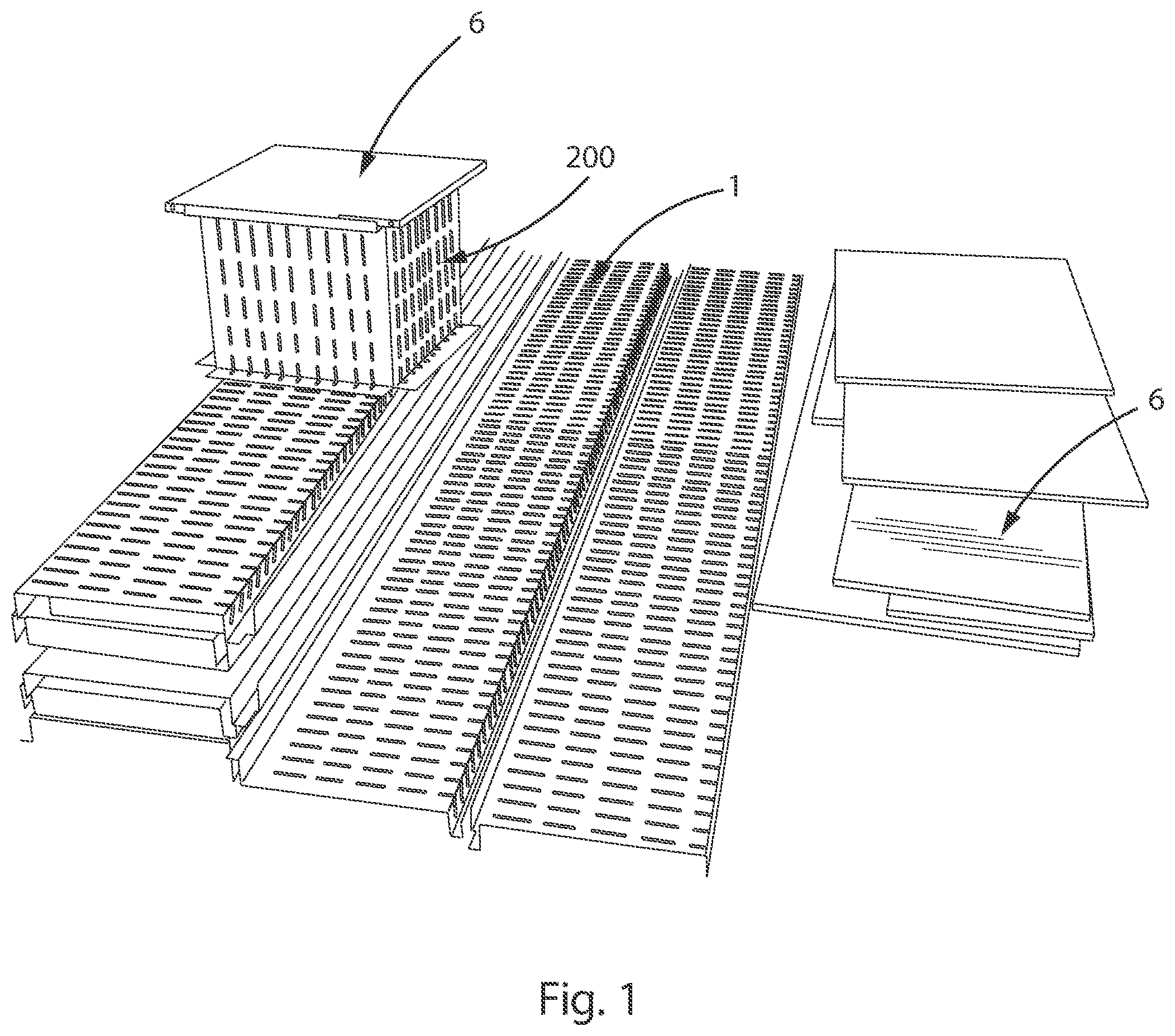
[0079] FIG. 1 shows an embodiment of the rough-in box 200 along with basic components of the box (single unitary pieces 1 and lids 6) as they will be provided to a job.
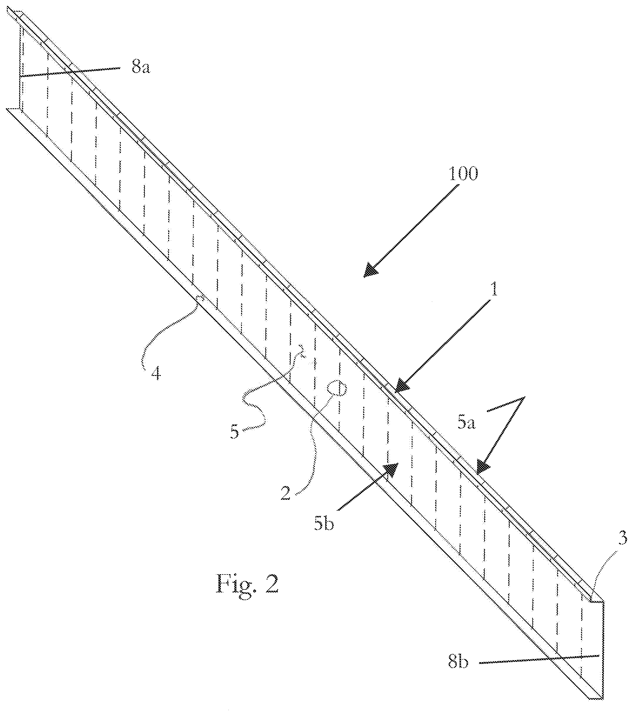
[0080] FIG. 2 shows a perspective view of the side profile of a single unitary piece 1 of kit 100 for a rough-in box 200 in an unassembled state. This single unitary piece 1 can be provided in various lengths to suit the application.
[0081] FIGS. 3a and 3b show the method by which the single unitary piece 1 is cut in specific locations so that it can be bent into the box shape required for the application.
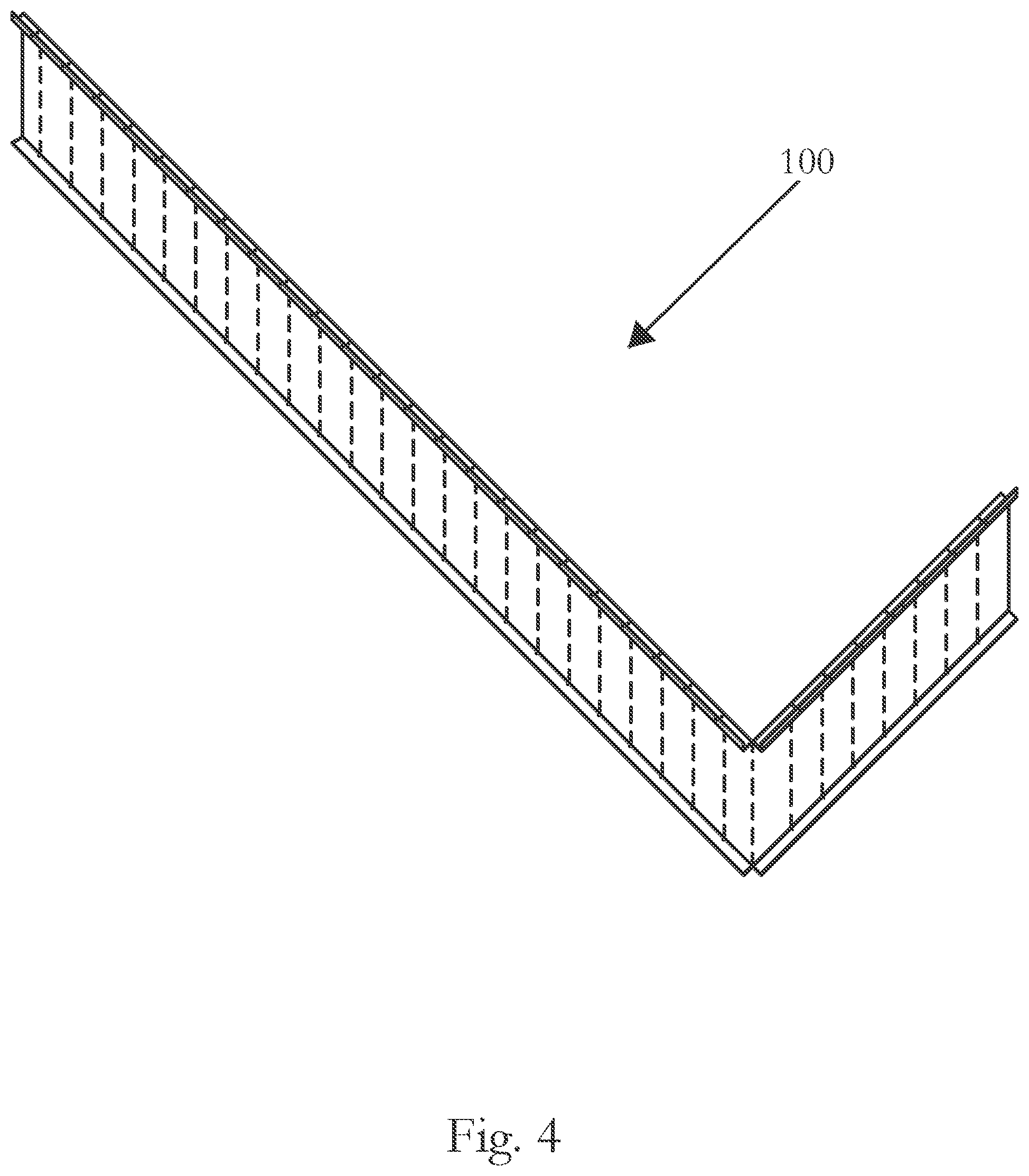
[0082] FIG. 4 shows the side profile of the single unitary piece 1 with a single 90 degree bend.
[0083] FIG. 5 shows an embodiment of a the side profile of the single unitary piece 1 with a 90 degree bend.
[0084] FIG. 6 shows the side profile of the single unitary piece 1 with a second 90 degree bend.
[0085] FIG. 7 shows the single unitary piece 1 side profile with the top and bottom flanges 3, 4 partially trimmed at one of the two ends 8a, 8b (e.g., left end 8a in FIGS. 7-9) and the resulting tab 11 bent at 90 degrees ready to overlap and attach to the other opposite end 8a, 8b of the single unitary piece 1 to form a closed box.
[0086] FIG. 8 shows the tab 11 referenced in FIG. 7 overlapping the opposite end of the single unitary piece 1 so that the opposite ends of the single unitary piece 1 (in this case the tab end and the opposite end) are ready to be attached to each other by screws 13 or other means.
[0087] FIG. 9 is a perspective view of the single unitary piece 1 bent into a completed rectangular rough-in box 200.
[0088] FIG. 10 shows the completed box 200 with a lid 6 attached, with an enlarged a detail showing an optional corner piece 10 that may be applied to protect the corner of the lid.
[0089] FIG. 11 shows a completed rough-in box 200 with optional corner pieces 10 and a lid 6 with a handle 9.
[0090] FIG. 12 shows a lid 6 being installed onto the top of the completed rectangular rough-in box 200.
[0091] FIG. 13 shows a plan view of the rough-in box 200 completed without the lid 6.
[0092] FIG. 14 shows a side view of the completed rectangular rough-in box 200.
[0093] FIG. 15 shows a side view of the rough-in box kit 100 in FIG. 2 along an end of the kit.
[0094] FIG. 16 shows cross sectional view of part of the rough-in box 200 after concrete has been poured.
[0095] FIG. 17 shows cross sectional view of one of the steel sections 12 of FIG. 18.
[0096] FIG. 18 shows a plan view of a version of the invention designed to cover a hole in an existing slab. This is comprised of steel sections 12 surrounding the perimeter of the hole fastened to the surrounding slab that support a cover.
[0097] FIG. 19 a perspective view of one of the steel sections 12 of FIG. 18.
[0098] FIG. 20 shows examples of fire rated rubber seals 14.
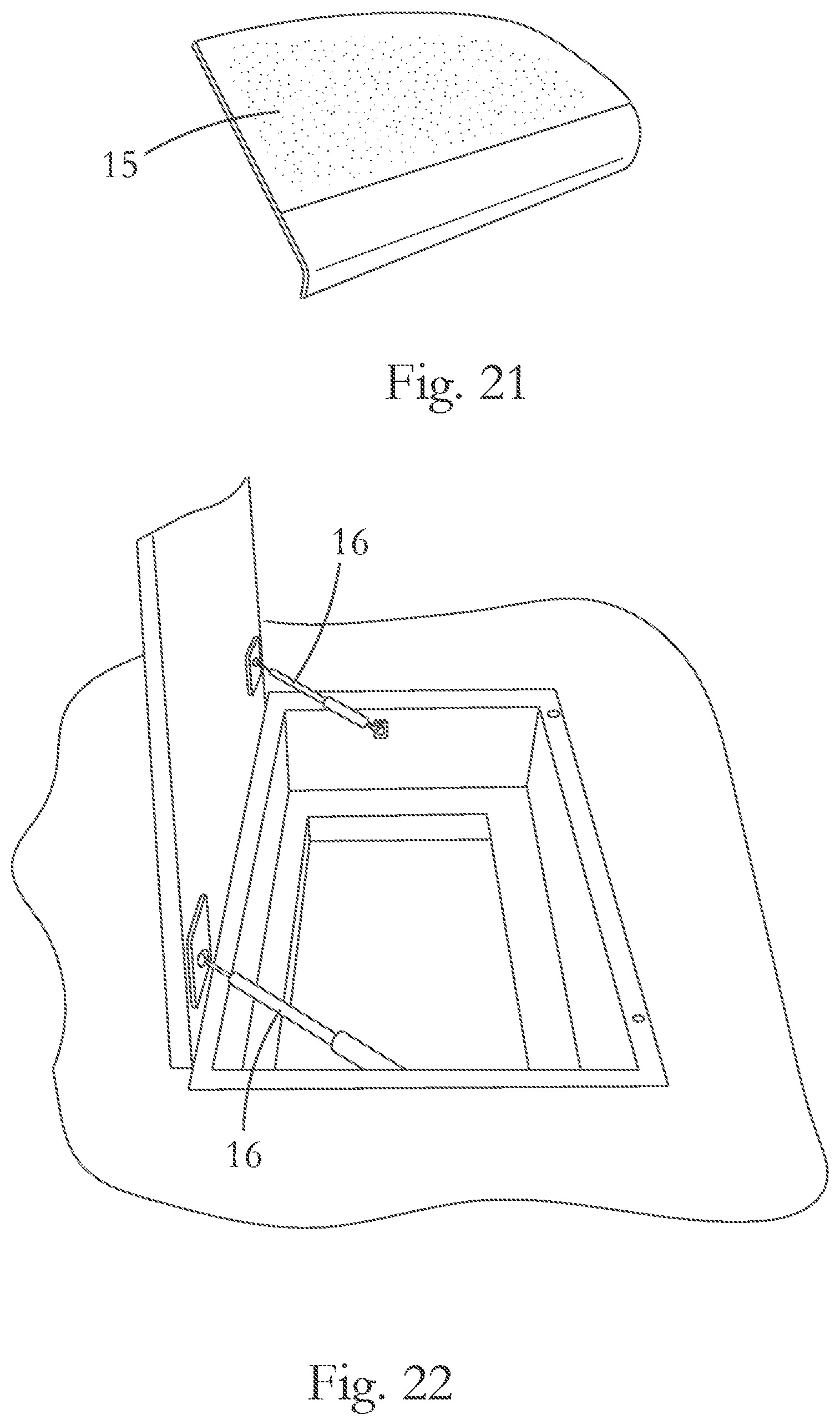
[0099] FIG. 21 shows a non-slip or slip resistant surface 15.
[0100] FIG. 22 shows a lid 6 with hydraulic hinges 16.
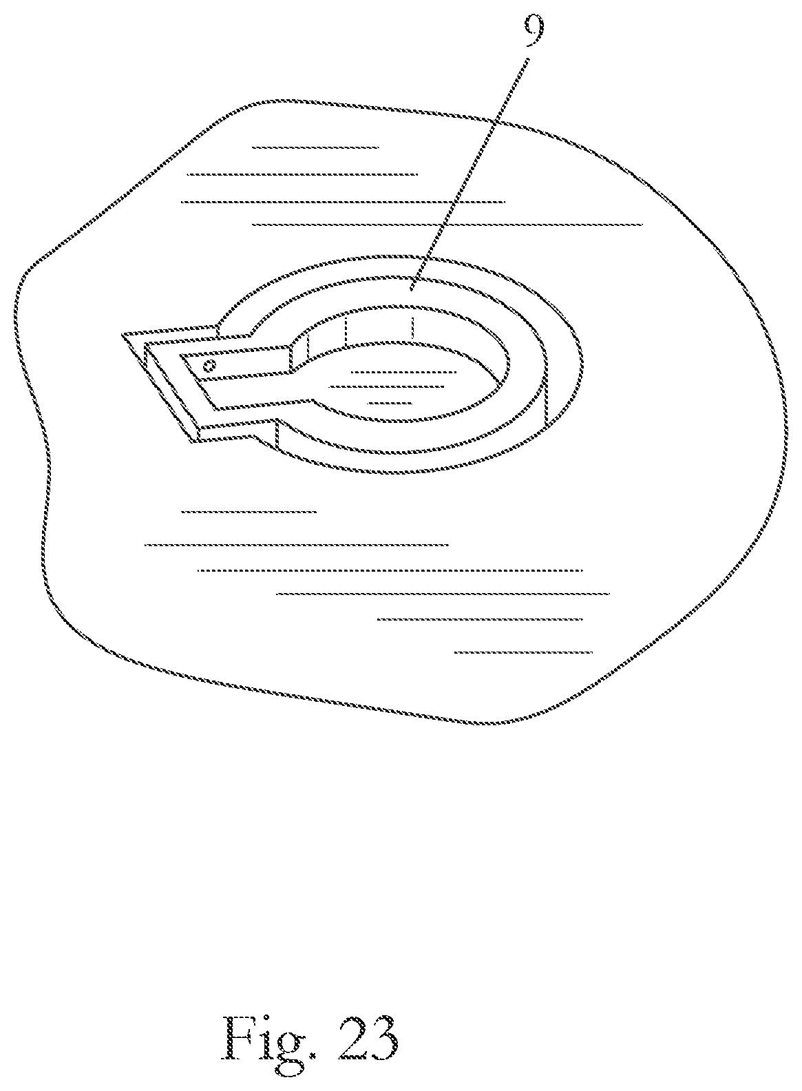
[0101] FIG. 23 shows an example of a handle 9 for the lid 6.
[0102] FIG. 24 shows examples of the different types of screw heads that can be used to effectively lock the lid 6 to the rough-in box 200.
[0103] FIGS. 25 and 26 show an optional deployable safety rail system 17.
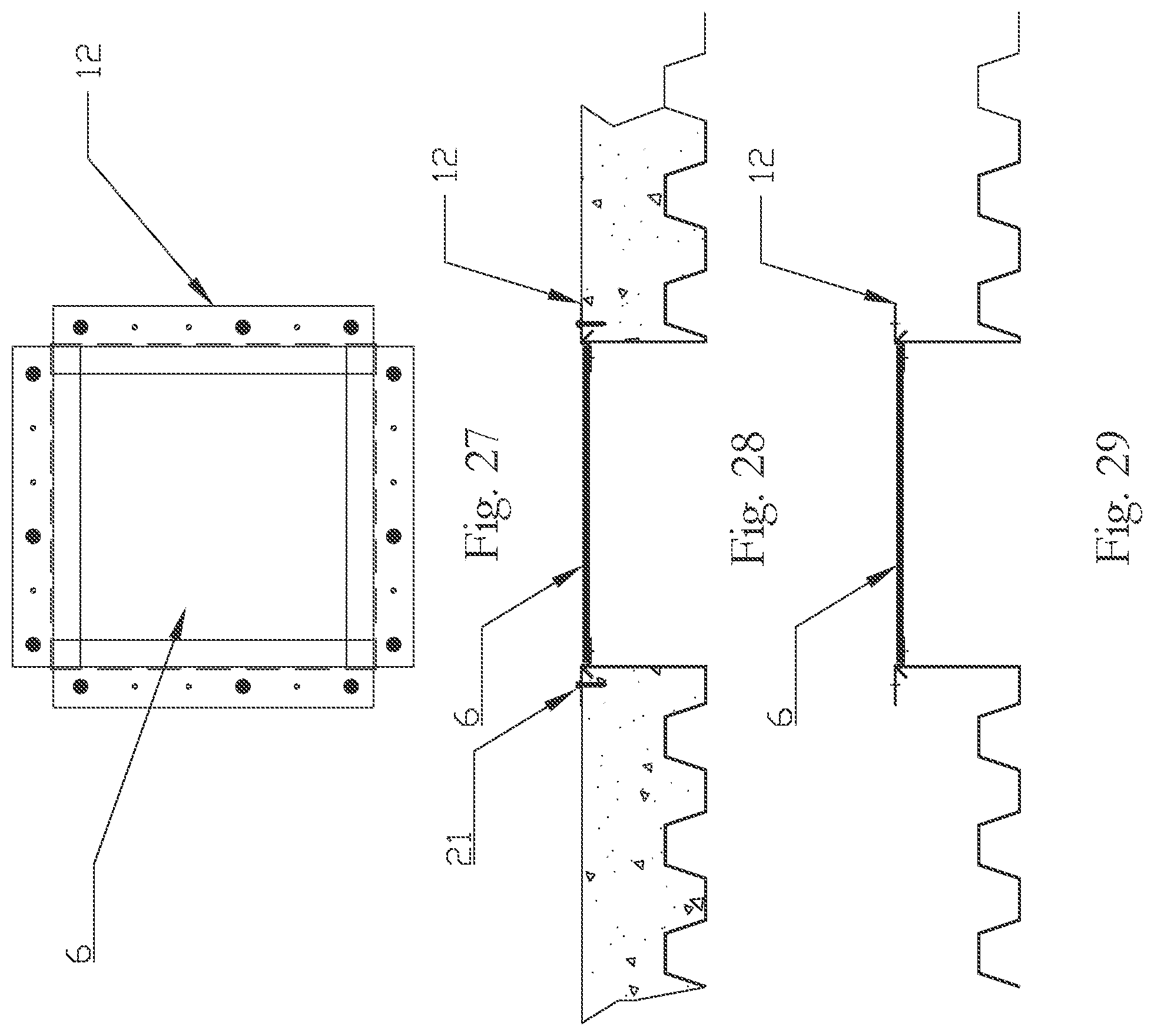
[0104] FIG. 27 is a plan view of the metal rough-in box 200 in place.
[0105] FIG. 28 shows a cross-section through the metal rough-in box 200 with the concrete deck poured.
[0106] FIG. 29 shows a cross-section through the metal rough-in box 200 prior to concrete placement.
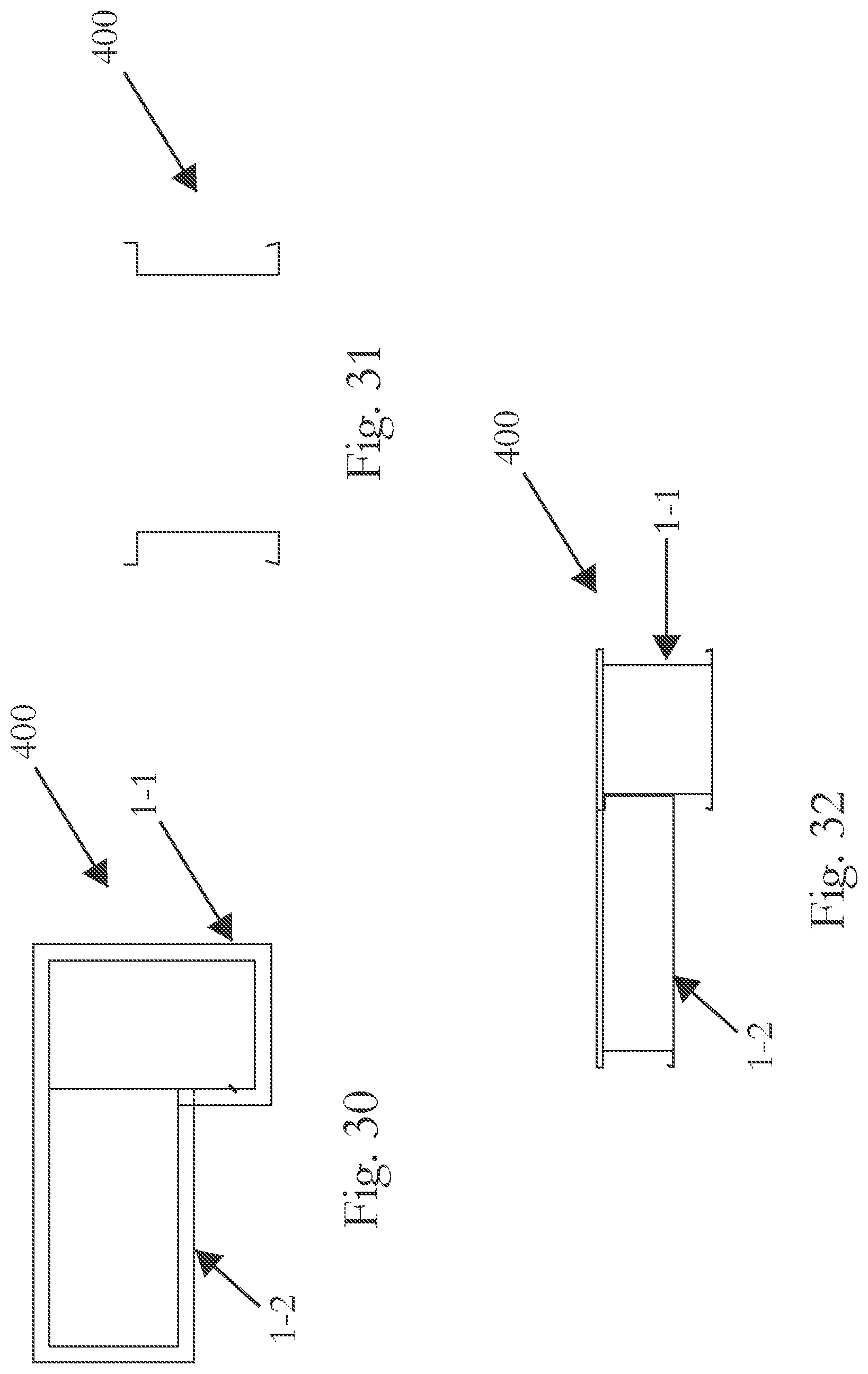
[0107] FIG. 30 is a plan view of a configuration 400 of multiple single unitary pieces 1 attached together to form a frame for a single depression of penetration.
[0108] FIG. 31 is a cross sectional view through line A-A of the configuration 400 of FIG. 30.
[0109] FIG. 32 is a side view of the configuration 400 in FIG. 30.
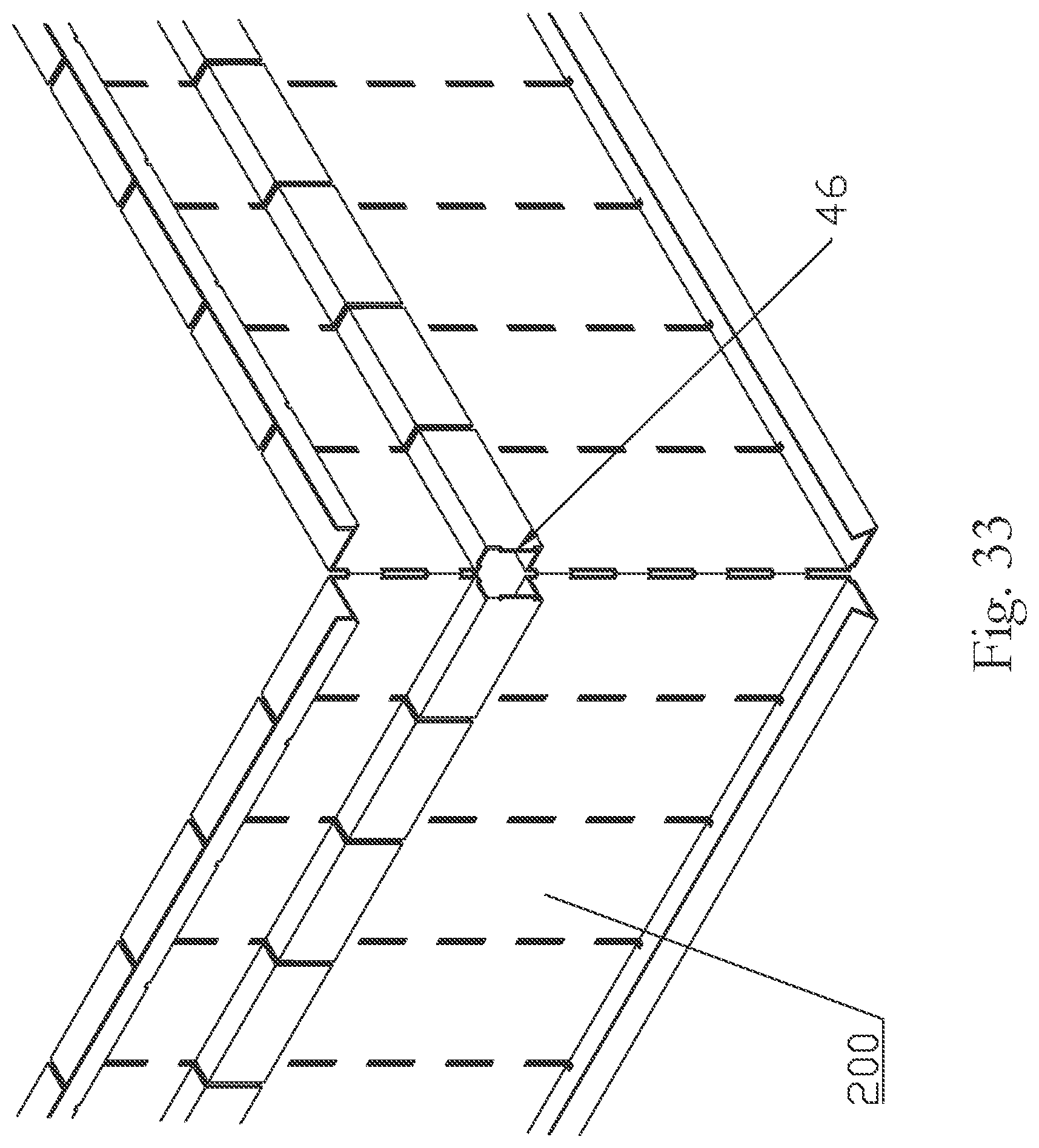
[0110] FIG. 33 shows an embodiment with a slot 46 in the side walls of the rough-in box 200 to receive expandable foam fireproofing.
DETAILED DESCRIPTION OF THE INVENTION
[0111] The present invention is directed to a mechanical rough-in and plumbing box 200 for creating penetrations in concrete flooring and a method of use.
[0112] FIG. 1 shows that these components--single unitary pieces 1 and lids 6--are capable of being flat packed such that they fit together when stacked on top of one another. This saves space when transporting and storing the components. Thus, the components can be delivered with fewer trucks, and take up less storage space at the jobsite.
[0113] In the embodiment of the present invention in FIG. 2, the rough-in box 200 is formed from a single unitary piece 1, which can be supplied in a single stock length to form rough-in boxes 200 of differing sizes and dimensions. The single unitary piece 1 is supplied with perforations, through-holes, or slots 2 in increments across their width. By snipping the top and bottom flanges 3, 4 of the single unitary piece 1 at locations corresponding to and lining with the perforations, through-holes, or slots 2, the profile may be bent or cut at any of the incremental lengths that correspond to the spacing of the perforations, through-holes, or slots 2, as shown in FIG. 3 and further shown in FIGS. 4, 5, 6, and 7. This feature allows the single unitary piece 1 to be formed into virtually any shape by varying the lengths between the bends and the angle of bends. The profile is fastened into a closed shape by trimming a short length of the flanges 3, 4 of one end 8a, 8b (e.g., left end 8a in FIGS. 7-11) of the single unitary piece 1 to form a tab 11, and then bending the resulting tab 11 (FIG. 7) to match the opposite end 8a, 8b (e.g., right end 8b in FIGS. 7-11) of the single unitary piece 1 and securing the two ends 8a, 8b by screws 13 or some other means. Should the shape of the desired rough-in box 200 exceed the longest length of the single unitary piece 1 supplied, a second single unitary piece 1 can be spliced to the first in a manner similar to that described above wherein a tab 11 is created by trimming the flanges 3, 4 of the piece 1 allowing the end 8a, 8b of one piece 1 to lie flat on the corresponding opposite end 8a, 8b of the second piece 1. The pieces 1 can then be spliced or affixed together with screws 13 or other appropriate means.
[0114] Preferably, the perforations, through-holes, or slots 2 are formed along vertical arrays 2a from the top of the single unitary piece 1 to the bottom of the bottom of the single unitary piece 1. This allows the single unitary piece 1 to be bent along straight lines to form the corners of the rough-in box 200. The vertical arrays 2a are spaced apart from each other at fixed increments along the width of the single unitary piece 1. Preferably the distance between adjacent vertical arrays 2a is constant. In one embodiment, the constant distance between the vertical arrays 2a is from 0.5 inches to 6.0 inches. Preferably, the constant distance between the vertical arrays 2a is from 0.5 inches to 3.0 inches. More preferably, the constant distance between the vertical arrays 2a is from 0.5 inches to 2.0 inches. Most preferably, the constant distance between the vertical arrays 2a is from 0.5 inches to 1.5 inches. In a particularly preferred embodiment, the constant distance between vertical arrays 2a is approximately 1.0 inches.
[0115] In another embodiment, the vertical arrays 2a of perforations 2 are spaced so that the perforations 2 also line up with each other horizontally to form horizontal arrays 2b that are perpendicular to the vertical arrays 2a.
[0116] Preferably, each perforation, through-hole, or slot 2 is formed in an oval or rectangular shape with its longest dimension extending along the same direction of the vertical array 2a in which it is arranged. This further facilitates bending the single unitary piece 1 to form the rough-in box 200.
[0117] The single unitary piece 1 consists of a flat section (web) 5, a top flange 3 which is shaped to support the box lid 6 flush with the surface of the concrete 300 (see FIG. 16), and a lower flange 4 that enhances the strength of the single unitary piece 1 and allows the finished box 200 to be securely fastened to the deck form. The flat section (web) 5 has an inside surface 5a and an outside surface 5b, with the inside surface 5a forming an inside surface of the final rough-in box 200 and the outside surface 5b forming an outside surface of the final rough-in box 200.
[0118] The rough-in box 200 is formed by snipping the flanges 3, 4 at locations corresponding to the perforations, through-holes, or slots 2, and bending the single unitary piece 1 along the perforations, through-holes, or slots 2 as required to attain the finished shape desired. Once the shape is attained the box 200 is fastened by securing the web tab 11 from one end 8a, 8b of the profile to the opposite end 8a, 8b.
[0119] In one embodiment, the profile of the rough-in box may be snipped and bent at very small intervals thereby creating a chorded circular shape.
[0120] There is no need to have a bottom surface on the rough-in box 200 as that would hinder the installation of plumbing, ducts, or other mechanical systems between floors. Thus, only a lid 6 needs to be opened so that these systems can be passed up from the floors below.
[0121] Once the side walls 7 of the rough-in box 200 are formed and the ends 8a, 8b joined together, the lid 6 is attached to the rough-in box 200. Each side wall 7 of the rough-in box has a top flange 3 to provide support for the lid 6 so that the lid 6 can is supported by each of the side walls 7 of the rough-in box 200.
[0122] The lid 6 is load bearing to permit workmen, equipment, vehicles, and materials to move over the lid 6 without risk of the lid 6 collapsing and caving in. Therefore, the lid 6 needs to be made from a strong enough material to provide a working surface on the floor while construction is being carried out. In one embodiment, the lid 6 is designed to support a weight of at least approximately 2,000 pounds concentrated load and approximately 200 pounds per square foot uniform load. The lid 6 can be made from fiberglass or from heavy duty plastics such as polyethylene, polyvinyl, and polypropylene. Additionally, in some embodiments, the lid 6 can be made from engineered wood. It is also possible that the lid 6 is made from a combination of fiberglass, heavy duty plastic, and/or engineered wood.
[0123] In one embodiment, the lid 6 can be made from resin impregnated fiberglass with the density of fibers being determined by the weight that the lid 6 has to bear. The resins used to make the lid 6 can include epoxy resins as well as other types of thermosetting plastics such as polyester or vinyl-ester resins and thermoplastics.
[0124] A fire rated rubber seal 14, such as the one shown in FIG. 20, can be added to the lid 6 for water resistance. The shape of the seal 14 should correspond to the shape of the lid 6 so that the seal 14 added to the under surface of the lid 6 of the rough-in box 200 to create a tight seal with the top flange 3 of the side walls 7 when the rough-in box 200 is closed. Waterproofing the rough-in box 200 allows sheetrock and other water-sensitive materials to be stored on floors below without worry of damage.
[0125] Optionally, compressed fireproofing can be embedded into the side walls 7 of the rough-in box 200. As shown in FIG. 33, a slot 46 can be left into the side walls of the rough-in box 200 to receive expandable foam fireproofing. Alternatively, an expandable fireproofing material--for example, expandable foam fireproofing material--can be affixed to the inside surface 5a of the single unitary piece 1 which will form an inside surface of rough-in box 200. After the rough-in box 200 is assembled and put into place, a worker can pull off a tape that will expose the expandable fireproofing material (e.g., expandable foam fireproofing). When the tape is removed, the fireproofing material will expand until it meets a solid barrier--for example, air conditioner ducts--such that when a duct is passed through the rough-in box 200, the fireproofing material is adhered to the surface of the duct. The fireproofing material can be an intumescent tape or any equivalent thereof. Intumescent materials that can be included in the tape include, for example, polyphosphates (such as ammonium polyphosphate) and materials that react with such phosphates such as pentaerythritol and melamine, or silicate-containing materials
[0126] If desired, the lid 6 can be supported by a strut (not shown) stretching across the box from an opening or vertical slot in one wall to an opening or vertical slot in an opposite wall to provide additional load bearing strength.
[0127] As shown in FIG. 22, the lid 6 may be equipped with hydraulic hinges 16 to control the speed at which the lid 6 opens and also to keep the lid 6 in a vertical open position when the lid 6 is opened by a worker working on the hole.
[0128] The lid can also be equipped with a lanyard or tether 20. The lanyard or tether 20 will provide positive attachment between the lid and the side walls of the box. The lanyard or tether 20 will allow lids to be removed but will insure that the lid is not removed from the immediate area of the opening.
[0129] The lid 6 can feature a grip and/or handle 9 for easy opening of the lid 6. An example of a handle is shown in FIG. 23.
[0130] Different locks/screw heads can be utilized to secure the lid 6 to the rough-in box 200 so that only certain personnel from a particular trade can open the rough-in box 200. For example, some designated rough-in boxes 200 can be equipped with a special screw head that can only be opened by plumbers, whereas other designated rough-in boxes 200 can be equipped with a different screw head that can only be opened by electricians. Examples of the different types of screw heads that can be used to effectively lock the lid 6 to the rough-in box 200 are shown in FIG. 24.
[0131] As a safety measure, the top side of the lid 6 can have a non-slip surface 15 so that workers and equipment moving over the lid 6 do not slip when crossing the rough-in box 200. A slip resistant surface that can be applied to the lid 6 is shown in FIG. 21.
[0132] As shown in FIGS. 25 and 26, the lid 6 can also be equipped with a deployable safety rail system 17 as an additional safety measure. The deployable safety rail 17 is a series of tubular members that are connected together and fastened to the rough-in box 200 and the lid 6 when the lid 6 is open to prevent accidental trips and falls due to the hole being open. The deployable safety rail 17 can be collapsed/de-constructed and stored in pieces within the rough-in box 200 on the underside 6a of the lid 6 for storage as shown in FIG. 25. When deployed, the tubular pieces of the safety rail 17 are removed from the underside of the lid 6, and are then assembled together atop the rough-in box 200 to form a rectangular prism that would prevent a worker from falling inside the hole of the rough-in box 200 when the lid 6 is open as shown in FIG. 26. The presence of the deployed safety rail 17 also acts as a warning to workers walking on the construction site that the lid 6 of the rough-in box 200 is open.
[0133] A sensing system that would alert workers and staff on the jobsite as to when a particular rough-in box has been left open can be included in the rough-in box 200. For example, a pressure sensor can be integrated into the lid 6, side walls 7, or both the lid 6 and side walls 7 of the rough-in box 200. When the lid 6 is closed, the sensor will register the applied pressure. When the lid 6 is open, no pressure will be detected by the sensor, and the sensor will then wirelessly relay to a visual display that the rough-in box 200 is open.
[0134] When installing the rough-in box 200, a numbering system can be used such that each box is numbered to match a corresponding hole at the jobsite. This ensures that the right rough-in box 200 goes over the correct hole. Also, if lids 6 are removed or placed over the wrong hole, this can be easily inspected and corrected.
[0135] The rough-in box 200 with the lid 6 attached allows holes to be covered prior to the pouring of concrete and stops leaks of concrete from entering the holes. When the concrete is poured to form the floor of a building, the lid 6 prevents over-pour from the concrete and creates a perfect edge that is level with the concrete when the concrete solidifies. Thus, there are no obstructions on the floor because the lid 6 will be flush with the concrete floor, allowing for the use of dollies, manlifts, modular scaffolding, and designated walkways because the lid 6 is load bearing and capable of handling loads from heavy machines and equipment. As a result, fewer safety personnel are needed and work shutdowns are minimized and reduced.
[0136] The rough-in box 200 of the present invention is embedded in the concrete floor, and only the lid 6 needs to be removed to complete mechanical work. When the lids 6 are removed, the lids 6 can be easily stacked and removed all together.
[0137] While the present invention has been described above in terms of specific embodiments, it is to be understood that the invention is not limited to these disclosed embodiments. Many modifications and other embodiments of the invention will come to the mind of those skilled in the art to which this invention pertains, and which are intended to be and are covered by both this disclosure and the appended claims. It is indeed intended that the scope of the invention should be determined by proper interpretation and construction of the appended claims and their legal equivalents, as understood by those of skill in the art relying upon the disclosure in this specification and the attached drawings.
[0138] The single unitary piece 1 may be formed of any strong, tough material. For example, the side walls can be made from an aluminum sheet, steel sheet, high strength plastic, or any other material that can be formed into the required shapes that has adequate strength.
[0139] The box or boxes 200 can be and fastened together by welding, rivets, screws 13, or any appropriate fastening method. The top will be left open. A flange 3 will be formed at the top of the boxes in a configuration as shown in FIG. 9. This flange 3 will serve to support a box lid 6 which will be installed in the box prior to placing concrete. The lid 6 will be flush with the surface of concrete after it is placed.
[0140] Different configurations 400 of boxes 200 may be made by joining individual boxes 200 of the required sizes, for example as shown in FIGS. 30-32. Typical configurations 400 can be a simple rectangular configuration 400 to form a straight trough or several boxes 200 may be connected in a configuration 400 to form penetrations having shapes resembling the letter "L", "T", or a cruciform shape in plan view.
[0141] This embodiment of the present invention solves many of the labor inefficiencies and costs incurred when creating void spaces in slabs for connecting plumbing fixtures. When the kits 100 for new boxes 200 or configurations 400 arrive on site, the boxes 200 are assembled prior to installation in the slab. They are delivered to the floor to be poured, and from there they are installed in a prearranged spot on the deck. To fasten the boxes 200 or configurations 400 in place, they are simply nailed to the wooden deck and are then ready for the pouring process. Unlike previous methods, the boxes 200 in the present invention stay in the concrete permanently this eliminates the need to grease or otherwise prepare the box 20 or configuration 400 to be stripped out of the floor as is required with current methods. The boxes 200 or configurations 400 are fitted with one or more covers 6 prior to placing the concrete so work around the boxes 200 or configurations 400 can proceed faster because workers do not have to worry about accidentally filling the boxes 200 or configurations 400 with concrete. The flush surface provided by the lid(s) 6 of the box 200 or configuration 400 also facilitates screeding and finishing the concrete around the boxes. The present invention eliminates the need to strip out rough-in boxes after the concrete is placed.
[0142] Current methods require the boxes to be pried out of the concrete to leave the appropriate void. Typically this removal of the boxes is done after the concrete fully sets, which is labor intensive, wastes time on the construction site, and can be hazardous to the workers removing the box. Additionally, concrete may overflow during placement and get inside the boxes and this must be cleaned out by workers.
[0143] Another benefit of the present invention is the top flange 3, which allows the lid 6 to sit flush with the surface of the concrete. Current methods require that plumbing boxes be covered with plywood hole covers that are proud of the concrete surface. These plywood covers are a tripping hazard and they interfere with the use of any wheeled devices for moving material around the floor.
[0144] According to conventional processes, the covers must be inspected daily for each floor. The present invention would drastically reduce this requirement, if not eliminate it completely, as the structural capabilities of the lid 6 would mean that the boxes 200 and configurations 400 would be able to withstand the loads and forces present on the site without failure. The reduction in inspection frequency would save on labor costs for the duration of the construction phase.
[0145] When the general contractor takes control of the floor, they do not need to add the additional covers for the holes. The plumber and mechanical services can immediately take responsibility for the boxes and run the pipework or shafts needed.
[0146] The proposed method greatly improves existing methods by the fact that it increases productivity and reduces labor costs, while also reducing the potential trip or fall hazards present with existing methods, which in turn reduces job stoppages from falls and injuries.
[0147] Another embodiment of the present invention will serve as a hole cover for penetrations that have been conventionally formed in a concrete slab or any hole in any floor that needs to be covered securely. In this embodiment, as shown in FIGS. 17-19, a frame of bent steel sections 12 is fastened in the opening and provided with a top lid 6 with sufficient strength to allow construction activities to safely proceed.
[0148] Each bent steel section 12 has a first extension 12a, a second extension 12b, and a third extension 12c. The first and third extensions 12a, 12c are approximately parallel to each other and extend in the same direction. The second extension 12b extends approximately perpendicular to the first and third extensions 12a, 12c to connect the first and third extensions 12a, 12c with each other.
[0149] The height of the second extension 12b (i.e., the up-down direction in FIG. 16) is preferably selected to correspond to a thickness of the top lid 6 that will be used so that a top of the lid 6 is flush with the top of the concrete floor 300--for example, approximately 0.5 inches. This reduces the chance of trips occurring while people work on the concrete floor 300.
[0150] Optionally, the first and third extensions 12a, 12c can include through holes 19, which allow the steel section 12 to easily be affixed to the concrete floor 300 by screws or bolts 13. The through holes 19 can also be used to secure the lid 6 to the steel section 12 by screws or bolts 13.
[0151] Preferably the steel sections 12 are placed around a hole in the concrete floor 300 so that ends 12d of two adjacent steel sections 12 overlap. This increases the strength of the platform formed by the first extensions 12a on which the lid 6 rests.
LIST OF REFERENCE NUMBERS
[0152] 1 single unitary piece [0153] 2 perforations, through-holes, or slots [0154] 2a vertical arrays of perforations, through-holes, or slots 2 [0155] 2b horizontal arrays of perforations, through-holes, or slots 2 [0156] 3 top flange [0157] 3a first extension of top flange 3 [0158] 3b second extension of top flange 3 [0159] 4 bottom flange [0160] 5 flat section (web) [0161] 5a inside surface [0162] 5b outside surface [0163] 6 lid [0164] 7 side walls [0165] 8a, 8b ends of the single unitary piece 1 [0166] 9 lid handle [0167] 10 corner piece [0168] 11 end tab [0169] 12 steel sections [0170] 12a first extension of steel sections 12 [0171] 12b second extension of steel sections 12 [0172] 12c third extension of steel sections 12 [0173] 12d ends of steel sections 12 [0174] 13 screws [0175] 14 fire rated rubber seal [0176] 15 non-slip surface [0177] 16 hydraulic hinges [0178] 17 safety rail system [0179] 18 bending lines [0180] 19 through holes [0181] 20 lanyard or tether [0182] 46 slot for fireproofing [0183] 100 rough-in box kit [0184] 200 rough-in box [0185] 300 concrete [0186] 400 configuration
* * * * *
D00000
D00001
D00002
D00003
D00004
D00005
D00006
D00007
D00008
D00009
D00010
D00011
D00012

D00013

D00014

D00015

D00016

D00017
D00018
D00019

D00020

D00021

D00022
D00023
D00024
XML
uspto.report is an independent third-party trademark research tool that is not affiliated, endorsed, or sponsored by the United States Patent and Trademark Office (USPTO) or any other governmental organization. The information provided by uspto.report is based on publicly available data at the time of writing and is intended for informational purposes only.
While we strive to provide accurate and up-to-date information, we do not guarantee the accuracy, completeness, reliability, or suitability of the information displayed on this site. The use of this site is at your own risk. Any reliance you place on such information is therefore strictly at your own risk.
All official trademark data, including owner information, should be verified by visiting the official USPTO website at www.uspto.gov. This site is not intended to replace professional legal advice and should not be used as a substitute for consulting with a legal professional who is knowledgeable about trademark law.