A Piece Of Three-dimensional Maze And Freely-constructible 3d Maze
TANAKA; Akihiko
U.S. patent application number 16/649251 was filed with the patent office on 2020-09-24 for a piece of three-dimensional maze and freely-constructible 3d maze. The applicant listed for this patent is AT idea Corporation. Invention is credited to Akihiko TANAKA.
| Application Number | 20200298099 16/649251 |
| Document ID | / |
| Family ID | 1000004905351 |
| Filed Date | 2020-09-24 |


| United States Patent Application | 20200298099 |
| Kind Code | A1 |
| TANAKA; Akihiko | September 24, 2020 |
A PIECE OF THREE-DIMENSIONAL MAZE AND FREELY-CONSTRUCTIBLE 3D MAZE
Abstract
A piece of three-dimensional maze, wherein at least two of six faces of a cube have opening faces such that a path connecting the opening faces of two faces is defined by flat plate of the cube.
| Inventors: | TANAKA; Akihiko; (Obama-shi, Fukui, JP) | ||||||||||
| Applicant: |
|
||||||||||
|---|---|---|---|---|---|---|---|---|---|---|---|
| Family ID: | 1000004905351 | ||||||||||
| Appl. No.: | 16/649251 | ||||||||||
| Filed: | September 20, 2018 | ||||||||||
| PCT Filed: | September 20, 2018 | ||||||||||
| PCT NO: | PCT/JP2018/034900 | ||||||||||
| 371 Date: | March 20, 2020 |
| Current U.S. Class: | 1/1 |
| Current CPC Class: | A63F 7/044 20130101; A63F 2250/50 20130101; A63F 7/042 20130101 |
| International Class: | A63F 7/04 20060101 A63F007/04 |
Foreign Application Data
| Date | Code | Application Number |
|---|---|---|
| Sep 21, 2017 | JP | 2017-197241 |
| Mar 8, 2018 | JP | 2018-060800 |
Claims
1-9. (canceled)
10. A U-shaped piece used for creating a three-dimensional maze, comprising: a first flat plate; a second flat plate connecting to the first flat plate at right angles; and a third flat plate connecting to the second flat plate at right angles on the side opposite to the first flat plate so as to face the first flat plate, wherein the three flat plates forms a continuous opening on continuous three opening faces of a cube, the cube having the three flat plates and the three opening faces, the continuous three opening faces directing to different three directions, and defining a path through the opening, wherein two ridgelines between the opening faces of two adjacent opening faces of the cube, each ridgeline does not exist in the opening faces of the three opening faces so that the path is opened outward.
11. A corner piece used for creating a three-dimensional maze, comprising: a first flat plate; a second flat plate connecting to the first flat plate at right angles; a third flat plate connecting to the second flat plate at right angles on the side opposite to the first flat plate so as to face the first flat plate; and a fourth flat plate connecting to each of the first, second, and third flat plates at right angles on a side perpendicular to the first, second, and third flat plates, wherein the four flat plates forms a continuous opening on continuous two adjacent opening faces of a cube, the cube having the four flat plates and the two opening faces, and defining a path through the opening, wherein a ridgeline between the two adjacent opening faces of the cube does not exist so that the path is opened outward.
12. A freely-constructible three-dimensional maze constructed by using at least one kind selected from the U-shaped piece according to claim 10 and the corner piece used for creating a three-dimensional maze, comprising: a first flat plate; a second flat plate connecting to the first flat plate at right angles; a third flat plate connecting to the second flat plate at right angles on the side opposite to the first flat plate so as to face the first flat plate; and a fourth flat plate connecting to each of the first, second, and third flat plates at right angles on a side perpendicular to the first, second, and third flat plates, wherein the four flat plates forms a continuous opening on continuous two adjacent opening faces of a cube, the cube having the four flat plates and the two opening faces, and defining a path through the opening, wherein a ridgeline between the two adjacent opening faces of the cube does not exist so that the path is opened outward.
13. A freely-constructible three-dimensional maze constructed by using at least one kind selected from the U-shaped piece used for creating a three-dimensional maze, comprising: a first flat plate; a second flat plate connecting to the first flat plate at right angles; and a third flat plate connecting to the second flat plate at right angles on the side opposite to the first flat plate so as to face the first flat plate, wherein the three flat plates forms a continuous opening on continuous three opening faces of a cube, the cube having the three flat plates and the three opening faces, the continuous three opening faces directing to different three directions, and defining a path through the opening, wherein two ridgelines between the opening faces of two adjacent opening faces of the cube, each ridgeline does not exist in the opening faces of the three opening faces so that the path is opened outward and the corner piece according to claim 11.
Description
BACKGROUND
1. Technical Field
[0001] The present invention relates to a piece for forming a three-dimensional maze in combination, and a freely-constructible three-dimensional maze constructed by using the pieces.
2. Description of the Related Art
[0002] Many of mazes on the market are constituted by two-dimensional planes and, for example, many of the mazes are played by changing an inclination of a maze plate to roll a ball etc. placed thereon.
[0003] Additionally, in proposed three-dimensional mazes, cubic pieces provided with ball paths are arranged or stacked so that a ball is moved between adjacent pieces e.g., as shown in Japanese Laid-Open Patent Publication No. 2006-619 (Patent Document 1), Japanese Laid-open Utility Model Application Publication No. H01-135988 (Patent Document 2), and Japanese Laid-open Utility Model Application Publication No. S62-61279 (Patent Document 3).
SUMMARY
[0004] However, in the three-dimensional mazes described in Patent Documents 1 to 3, paths are formed by piercing holes in cubes, which takes time and costs, and are difficult to form for mold molding due to bending and intersecting of paths in the pieces, and therefore, the pieces of three-dimensional maze were not easily mass-produced.
[0005] It is therefore one non-limiting and exemplary embodiment provides a piece of three-dimensional maze that is easy to create.
[0006] In one general aspect, the techniques disclosed here feature: a piece of three-dimensional maze, wherein at least two of six faces of a cube have opening faces such that a path connecting the opening faces of two faces is defined by flat plates of the cube.
[0007] The piece of three-dimensional maze according to the present invention can relatively easily be formed since the path connecting the opening faces of two faces to each other is defined by flat plates of a cube.
BRIEF DESCRIPTION OF DRAWINGS
[0008] The present disclosure will become readily understood from the following description of non-limiting and exemplary embodiments thereof made with reference to the accompanying drawings, in which like parts are designated by like reference numeral and in which:
[0009] FIG. 1A is a schematic perspective view of a 2.times.2.times.2 three-dimensional maze made up only of eight corner pieces each having a path bent at a right angle.
[0010] FIG. 1B is a schematic perspective view showing the three-dimensional maze housed in a box.
[0011] FIG. 2A is a schematic perspective view of a 2.times.2.times.2 three-dimensional maze made up only of eight U-shaped pieces. FIG. 2B is a schematic perspective view showing the three-dimensional maze housed in the box.
[0012] FIG. 3 is a schematic perspective view showing an example of connection of paths between the U-shaped piece and the corner piece.
[0013] FIG. 4 is a schematic perspective view showing an example of connection of paths using the U-shaped pieces, a straight piece, and the corner piece.
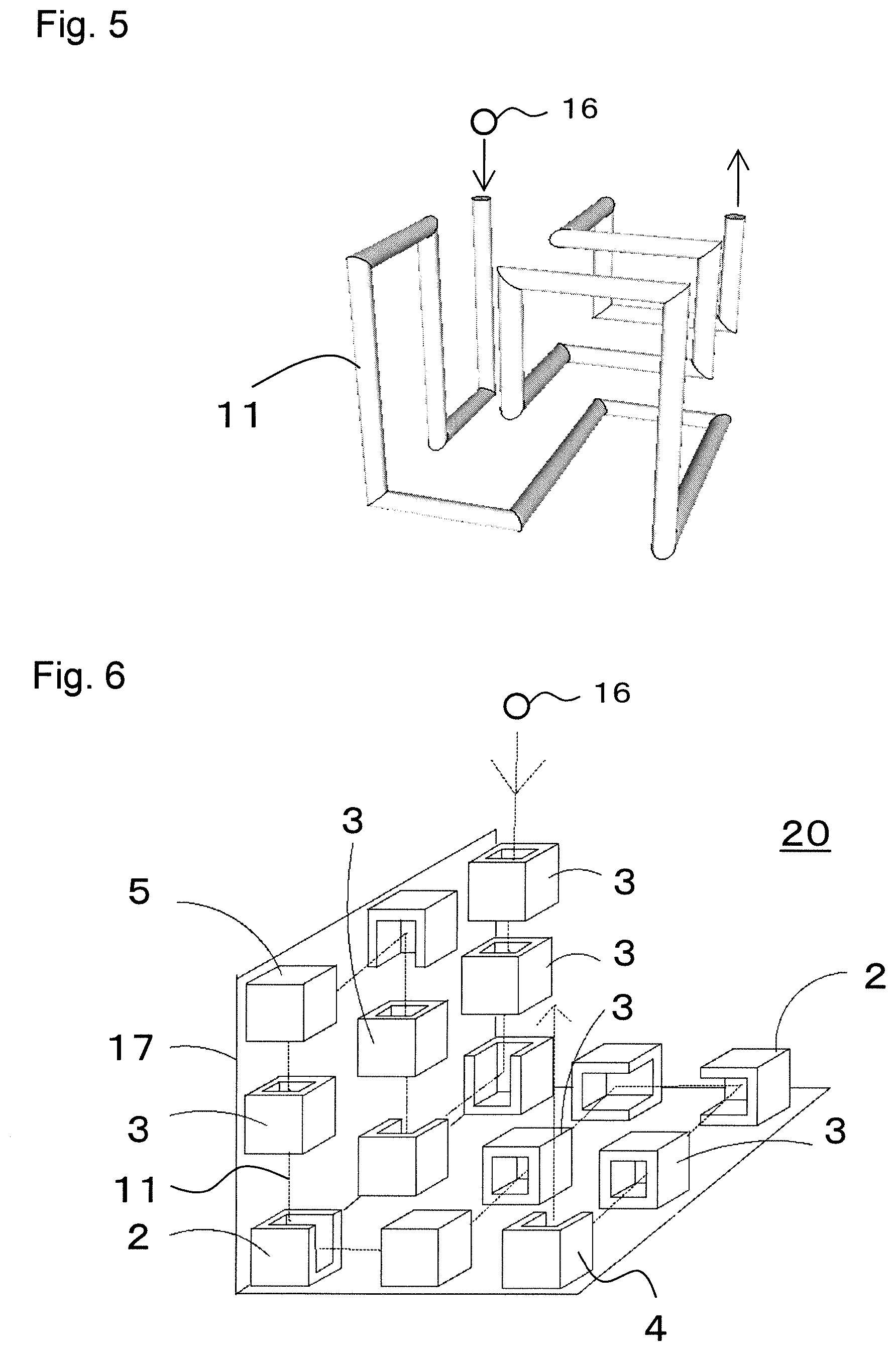
[0014] FIG. 5 is a schematic view showing an example of a route passing through all pieces of a 3.times.3.times.3 three-dimensional maze.
[0015] FIG. 6 is a schematic perspective view of 15 straight and corner pieces arranged on two left and lower faces of FIG. 5.
[0016] FIG. 7A is a schematic perspective view in which all the pieces of FIG. 5 are replaced only with U-shaped pieces. FIG. 7B is a schematic perspective view showing a state of the pieces of FIG. 7A housed in the box made up of three faces.
[0017] FIG. 8A is a schematic perspective view showing a 3.times.3.times.3 three-dimensional maze in which 12 corner and straight pieces are added to the configuration of FIG. 7A. FIG. 8B is a schematic perspective view showing a 3.times.3.times.3 three-dimensional maze made up of 27 pieces of FIG. 8A housed in the box.
[0018] FIG. 9 is a schematic perspective view of a 3.times.3.times.3 three-dimensional maze made up of opaque pieces of three-dimensional maze provided with peepholes on faces without an opening face.
[0019] A piece of three-dimensional maze according to a first aspect, at least two of six faces of a cube have opening faces such that a path connecting the opening faces of two faces is defined by flat plate of the cube.
[0020] The piece of three-dimensional maze according to a second aspect, in the first aspect, at least two adjacent faces of the six faces of the cube may have opening faces continuous over the two faces.
[0021] The piece of three-dimensional maze according to a third aspect, in the first or second aspect, the flat plates of the cube constituting the path may have a thickness equal to or less than 1/3 of the length of one side of the cube.
[0022] The piece of three-dimensional maze according to a fourth aspect, in any one of the first to third aspect, the flat plates of the cube constituting the path may include a curved surface.
[0023] The piece of three-dimensional maze according to a fifth aspect, in any one of the first to fourth aspect, the piece may be a corner piece in which two adjacent faces of the six faces of the cube have opening faces continuous over the two faces such that a path connecting the opening faces of the two faces to each other is defined by the flat plate of the cube.
[0024] The piece of three-dimensional maze according to a sixth aspect, in any one of the first to fifth aspect, the piece may be a U-shaped piece in which three faces continuous along one direction among the six faces of the cube have opening faces continuous over the three faces such that a path connecting the opening faces of the three faces to each other is defined by the flat plates of the cube.
[0025] The piece of three-dimensional maze according to a seventh aspect, in any one of the first to sixth aspect, eight vertices of the cube may be maintained.
[0026] The piece of three-dimensional maze according to an eighth aspect, in any one of the first to seventh aspect, the flat plates of the cube defining the path may have openings.
[0027] A three-dimensional maze according to a ninth aspect constructed by using the piece of three-dimensional maze according to the fifth aspect or the sixth aspect.
[0028] Pieces of three-dimensional maze and a three-dimensional maze according to an embodiment will now be described with reference to the accompanying drawings. In the drawings, substantially the same members are denoted by the same reference numerals.
First Embodiment
[0029] FIG. 1A is a schematic perspective view of a 2.times.2.times.2 three-dimensional maze made up only of eight corner pieces 2 each having a path bent at a right angle. FIG. 1B is a schematic perspective view showing the three-dimensional maze 10 housed in a box 17b. FIG. 2A is a schematic perspective view of a 2.times.2.times.2 three-dimensional maze made up only of eight U-shaped pieces 4. FIG. 2B is a schematic perspective view showing the three-dimensional maze 10a housed in the box 17b. FIG. 3 is a schematic perspective view showing an example of connection of paths between the U-shaped piece 4 and the corner piece 2. FIG. 4 is a schematic perspective view showing an example of connection of paths using the U-shaped pieces 4, a straight piece 3, and the corner piece 2.
[0030] In the pieces of three-dimensional maze 2, 3, 4 according to the first embodiment, at least two of six faces of a cube have opening faces on the at least two of six faces. Therefore, the opening faces are supported by flat plates of the cube. A path connecting the two opening faces is defined by flat plates of the cube. Furthermore, the flat plates of the cube constituting the path have a thickness equal to or less than 1/3 of the length of one side of the cube.
[0031] The pieces of three-dimensional maze 2, 3, 4 can relatively easily be formed since the path connecting the opening faces of two faces is defined by the plates of the cube.
[0032] The flat plate of the cube constituting the path only needs to be able to define a ball path, and the flat plate constituting the path may be a flat face or a curved surface or may be a flat face partially having a curved surface. As a result, the piece of three-dimensional maze can easily be formed. The flat plate may be a polygonal face or an uneven face. The flat plate may have a slope along a direction of the path. The flat plate may have a substantially constant thickness. The flat plate of the cube only needs to be able to define a path, has a thickness equal to or less than 1/3 of one side of the cube, for example, and preferably has a thickness capable of maintaining a certain strength, for example, a thickness of 1 mm or more, more preferably 3 mm or more. As a result, when the pieces of three-dimensional maze are stacked, the faces thereof come into contact with each other at portions having the thickness, so that the faces of the pieces can be prevented from fitting in each other. For example, the flat plate of the cube can be made of resin, metal, wood, cardboard, etc. For uniform formation, the flat plate is preferably made of resin. The flat plate of the cube may be transparent or opaque. Furthermore, as shown in FIG. 9, a peephole 8 may be disposed in the face of the cube.
[0033] Preferably, two adjacent faces have opening faces continuous over the two faces. In this case, a side serving as a ridgeline between the two faces does not exist, and the continuous opening faces are opened outward, resulting in a structure easily formed by mold molding. Examples of the piece of three-dimensional maze with two adjacent faces having continuous opening faces include the corner piece 2 and the U-shaped piece 4 described later.
[0034] In this piece of three-dimensional maze, among the eight vertices and the 12 sides of the cube, a discontinuous side may be included; however, the eight vertices are preferably maintained. When the pieces of three-dimensional maze are stacked up, the pieces of three-dimensional maze maintaining the eight vertices of the cube produce an effect of stabilizing the three-dimensional maze. For example, a straight piece, a corner piece, and a U-shaped piece described later maintain eight vertices and are therefore stable when stacked.
[0035] The corner piece 2, the U-shaped piece 4, and the straight piece 3 are specific examples of the pieces of three-dimensional maze 2, 3, 4 and will hereinafter be described.
<Corner Piece>
[0036] FIG. 1A is a schematic perspective view of a 2.times.2.times.2 three-dimensional maze 10 made up only of the eight corner pieces 2 each having a path bent at a right angle. FIG. 1B is a schematic perspective view showing the three-dimensional maze 10 housed in a box 17b.
[0037] The corner piece 2 will be described with reference to FIGS. 1A and 1B. In the corner piece 2, two faces adjacent to each other among the six faces of the cube have opening faces 9a, 9b continuous over the two faces. Entrances 12a, 12b connecting the two opening faces 9a, 9b to each other are defined by flat plates of the cube. In the corner piece 2, the two faces form the opening faces 9a, 9b continuous over the two faces without a side serving as a ridgeline between the two faces and the opening faces 9a, 9b are opened outward. Therefore, mold molding can easily be performed. Although the corner piece 2 has one discontinuous side among the eight vertices and 12 sides of the cube, the eight vertices of the cube are maintained. Since the eight vertices are maintained, the piece is stable when stacked up to form a three-dimensional maze.
[0038] A ball 16 enters the corner piece 2 via one opening face 9a of the opening faces and exits the corner piece 2 via the other opening face 9b in a right-angle direction. Therefore, in the corner piece 2, the ball path (9a->9b) bends at a right angle (right-angle path). When the opening face 9a of another piece comes into contact with the opening face 9b on one side of the right-angle path of the corner piece 2, the right-angle path forms a portion of a continuous path. By combining the eight corner pieces 2 such that the paths thereof are made continuous, the three-dimensional maze 10 is configured to have a route 11 in which the paths of the corner pieces 2 are made continuous. The combination of the corner pieces 2 of FIG. 1 is an example and is not limited thereto.
<U-Shaped Piece>
[0039] FIG. 2A is a schematic perspective view of a 2.times.2.times.2 three-dimensional maze 10a made up only of the eight U-shaped pieces 4. FIG. 2B is a schematic perspective view showing the three-dimensional maze 10a housed in the box 17b.
[0040] The U-shaped piece 4 will be described with reference to FIGS. 2A and 2B. In the U-shaped piece 4, three faces continuous along one direction among the six faces of the cube form opening faces 9a, 9b, 9c continuous over the three faces. Entrances 12a, 12b, 12c connecting the three opening faces 9a, 9b, 9c to each other are defined by flat plates of the cube. In the U-shaped piece 4, the three faces form the opening faces 9a, 9b, 9c continuous over the three faces without two sides each serving as a ridgeline between two adjacent faces and the opening faces 9a, 9b, 9c are opened outward. Therefore, mold molding can easily be performed. Although the U-shaped piece 4 has two discontinuous sides among the eight vertices and 12 sides of the cube, the eight vertices of the cube are maintained. Since the eight vertices are maintained, the piece is stable when stacked up to form a three-dimensional maze. The U-shaped piece 4 is based on the fact that the shape of three continuous faces other than the opening faces is a U-shape when viewed in the one direction. Both end portions of the three continuous faces defining the path are also referred to as legs. Since the U-shaped piece has the three opening faces 9a, 9b, 9c as shown in FIGS. 3 and 4(a) described later, the ball path has the three entrances 12a, 12b, 12c.
[0041] As shown in FIG. 4(b), depending on arranging the U-shaped piece 4, one of the three entrances 12a, 12b, 12c can be sealed at the lower face 17 so as to allow the piece to function as if it were a straight piece or a corner piece. Therefore, one of the three entrances may be sealed with a face of another piece or a face of the box.
[0042] Since the U-shaped piece 4 has three entrances, it is required to consider the arrangement of the piece more than when the straight piece 3 or the corner piece 2 is used, which is suitable for a brain training.
<Straight Piece>
[0043] FIG. 4(c) is a schematic view showing a path of the straight piece 3. In the straight piece 3, two opposite faces of the cube are the opening faces 9a, 9b. The entrances 12a, 12b connecting the two opening faces 9a, 9b to each other are defined by flat plates of the cube. In the straight piece 3, the two faces are the opening faces 9a, 9b. Among the eight vertices and the 12 sides of the cube, the straight piece 3 has no discontinuous side and maintains the eight vertices of the cube and is therefore stable when stacked up to form a three-dimensional maze. In this straight piece 3, the path from the entrance 12a to the entrance 12b is straight, and the three-dimensional maze cannot be made up only of the straight pieces 3. Therefore, for example, as shown in FIG. 4(c), a three-dimensional route can be formed by connecting the entrance 12b of the straight piece 3 to the entrance 12a of the corner piece 2 so that the path is bent at a right angle and lead to the entrance 12b by the corner piece 2.
<Other Pieces>
[0044] As described later, a three-dimensional maze may be formed by using a cubic piece composed of six faces all closed and having no opening face or a blind-end piece composed of one face that is an opening face and the other five faces having no opening face. These cubic and blind-end pieces are not primary constituent members of the three-dimensional maze in that the pieces do not form a route.
<Connection of Paths>
[0045] FIG. 3 is a schematic perspective view showing an example of connection of paths between the U-shaped piece 4 and the corner piece 2. FIG. 4(a) is a schematic perspective view showing the entrances 12a, 12b, 12c of the U-shaped piece 4, FIG. 4(b) is a schematic perspective view showing connection of the paths according to arrangement of the two U-shaped pieces, and FIG. 4(C) is a schematic perspective view showing connection of paths from the straight piece 3 to the corner piece 2.
[0046] As shown in FIGS. 3 and 4(a), the U-shaped piece 4 has the three entrances 12a, 12b, 12c, and in FIG. 3, the path of the corner piece 2 is connected to the entrance 12b to form a route.
[0047] As shown in FIG. 4(b), the U-shaped piece 4 can be arranged to seal one of the three entrances. For example, in the U-shaped piece 4 on the lower side of FIG. 4(b), a leg lower face of a U-shaped portion is closed, so that the path of the entrances 12a, 12b is straight as in the straight piece. in the U-shaped piece 4 on the upper side of FIG. 4(b), one face of the U-shaped portion is closed, so that the path of the entrances 12c, 12b has a right angle as in the corner piece. As shown in FIG. 4(c), the straight path formed by the straight piece 3 can be bent at a right angle by the corner piece 2. In FIG. 7, arrangement of the U-shaped pieces and a route of a maze are shown by using 15 U-shaped pieces.
[0048] As described above, the paths of the pieces can appropriately be connected to provide a route for forming a three-dimensional maze.
<3.times.3.times.3 Three-Dimensional Maze>
[0049] A 3.times.3.times.3 three-dimensional maze is made up of 27 pieces, and 1000 or more different routes are available from the start piece to the goal piece, including pieces that the routes do not pass through. FIG. 5 is an example of a route 11 passing through all the 27 pieces from the start to the goal, and FIGS. 6, 7, and 8 show examples of piece arrangement according to the route 11. FIG. 6 is a schematic perspective view of the 15 corner and straight pieces 2 and 3 arranged on two left and lower faces 17 of FIG. 5.
[0050] FIG. 7A is a schematic perspective view in which all the corner and straight pieces 2 and 3 of FIG. 5 are replaced with the U-shaped pieces 4. FIG. 7B is a schematic perspective view showing a state of the 15 pieces of FIG. 7A housed in the box 17b made up of three faces. FIGS. 7A and 7B show that the U-shaped piece 4 serves as a substitute for the corner piece 2 and the straight piece 3 by using the face 17 of the box or the face of the adjacent piece. The brain is trained by simply considering how to arrange the U-shaped pieces 4. FIG. 8A is a schematic perspective view showing arrangement of a total of 27 pieces when 12 corner and straight pieces 2 and 3 are added to the configuration of FIG. 7A. FIG. 8B is a schematic perspective view showing a 3.times.3.times.3 three-dimensional maze 20b made up of 27 pieces of FIG. 8A housed in the box 17b. When the three-dimensional maze is used, the ball 16 is put into the piece at a start portion; a box 17a is used as a lid; and the box 17b and the box 17a are fixed by a band before the maze is rotated and used with both hands.
<Branch Point>
[0051] As shown in FIG. 5, a route passing through all the 27 pieces without a branch point forms a relatively easy maze. Since the U-shaped piece 4 has three entrances, a branch portion can be formed in the maze to increase difficulty. A two-dimensional maze commonly has branch portions and blind ends, and a three-dimensional maze having branch portions and blind ends is more interesting and greatly increased in difficulty. Additionally, in each of the corner pieces 2, the straight pieces 3, and the U-shaped pieces 4, a branch portion may be increased by disposing an opening allowing passage of a ball in a flat plate of a cube constituting a path. In this case, a frame surrounding the opening of the flat plate of the cube is retained. As a result, even if the number of openings is increased, the vertices of the cube can be maintained, and the stability can be kept.
<Peephole>
[0052] FIG. 9(a) is a schematic perspective view showing the straight piece 3 provided with the peepholes 8 on faces without an opening face, and FIG. 9(b) is a schematic perspective view showing the corner piece 2 provided with the peepholes 8 on faces without an opening face, FIG. 9(c) is a schematic perspective view of a 3.times.3.times.3 three-dimensional maze 20c made up of the pieces 1 of pieces of three-dimensional maze 1 provided with the peepholes 8 on faces without an opening face, and FIG. 9(d) is a schematic perspective view showing a box 7 and a lid 15 for storing the three-dimensional maze 20c.
[0053] In an example shown in FIG. 9, the 3.times.3.times.3 three-dimensional maze 20c is formed by using the straight pieces 3 and the corner piece 2 made of an opaque material and is housed in the box 7. An example of the route of the ball 16 is the same as FIG. 6, for example. This three-dimensional maze 20c is made up of a total of 27 pieces, and as shown in FIG. 6, the route 11 is long so that the position of the ball 16 in the route 11 may become unclear. Therefore, the peepholes 8 not hindering the movement of the ball 16 are disposed on wall surfaces of the corner pieces 2 and the straight pieces 3 to clarify the location of the ball 16. The peepholes 8 may freely be formed in terms of shape, size, and number as long as the position of the ball 16 can be observed. Alternatively, transparent and opaque pieces may be mixed to form a three-dimensional maze. If the box 7 is opaque, multiple holes may be disposed on the faces of the box 7 so that the peepholes 8 can be seen. When neither the peepholes 8 nor the holes on the faces of the box exist, the ball is not visible so that the difficulty of the three-dimensional maze increases.
[0054] The peepholes may be increased in diameter to form an opening allowing passage of the ball.
[0055] Although the three-dimensional maze may have any size, the maze with each side of about 60 mm is easy to use when played with both hands, for example. In the case of the 3.times.3.times.3 three-dimensional maze, one side of one piece is about 20 mm. To prevent adjacent pieces from fitting in each other, the thickness of each face of one piece of three-dimensional maze is preferably 1 mm or more, more preferably 3 mm or more. Additionally, the piece of three-dimensional maze becomes stable when four corners at least in contact with the center of one side of the cube are large. When the faces of the straight piece have the thickness of 3 mm, the inner cavity is 14 mm in width, and a ball having a diameter of about 13 mm can be rolled. In the case of a 4.times.4.times.4 maze, the piece is 15 mm on each side. If the thickness of each face of the piece of three-dimensional maze is 3 mm, the cubic inner cavity is 9 mm in width, and a ball having a diameter of about 8 mm can be rolled.
[0056] The 3.times.3.times.3 three-dimensional maze has 27 passage portions, and the 4.times.4.times.4 three-dimensional maze has 64 passage portions. In this case, when a large three-dimensional maze is created, it is not necessary to arrange the pieces of three-dimensional maze having paths at all locations. For example, a space may be filled in some locations with a regular hexahedron piece having six closed faces or a box-shaped blind-end piece made up of five faces with one face removed. Additionally, a transparent piece, an opaque piece, and a colored piece may be mixed. This can make the maze visually enjoyable.
[0057] Furthermore, the three-dimensional maze may be played by causing the ball to make a round trip between two entrances. Alternatively, in a 4.times.4.times.4 or more three-dimensional maze having an increased maze space, a goal may be disposed inside the three-dimensional maze so that the maze is solved by making a round trip. Furthermore, according to the piece of three-dimensional maze, a three-dimensional maze can freely be constructed, which allows a player to conceive various ways by himself/herself.
<Mold Molding>
[0058] The pieces of three-dimensional maze have a path defined by plates of a cube such that the path is made wide for a ball, and particularly, the corner piece 2 and the U-shaped piece 4 have the path opened outward, so that the pieces are easily formed by mold molding. If path surfaces are sloped and opened outward and outside surfaces are also sloped, the pieces have a structure easily formed by mold molding and can be mass-produced. In this case, a side length of a piece of 20 mm on each side is reduced by about 0.5 mm in some positions; however, this does not affect when the maze is created by the pieces or is played.
[0059] The pieces of three-dimensional maze and the freely-constructible three-dimensional maze using the pieces provide the following effects.
[0060] (A) The three-dimensional maze can be solved by guiding the ball from an entrance to an exit by rotating the entire three-dimensional maze, for example, and can be created by connecting the paths of the pieces of three-dimensional maze from an entrance to an exit. In this case, the route of the ball is three-dimensionally imaged in the brain at the time of both creating and solving the three-dimensional maze, so that the brain is trained.
[0061] (B) Since the multiple types of the pieces of three-dimensional maze are provided, the pieces are enjoyably selected when a route of the of the three-dimensional maze is created.
[0062] (C) Since the ball path is formed by flat plates of a cube in each of the pieces of three-dimensional maze, a relatively large ball can be put in the path.
[0063] (D) Since the ball path is formed by open faces of a regular hexahedron rather than by drilling a hole in a cubic piece, the pieces of three-dimensional maze are easily formed by mold molding.
[0064] (E) Since the ball path is formed by flat plates of a cube in each of the pieces of three-dimensional maze, less material is required, and manufacturing costs can be reduced.
[0065] The present disclosure includes appropriately combining any embodiments and/or examples out of the various embodiments and/or examples described above, and the effects of the respective embodiments and/or examples can be produced.
[0066] The piece of three-dimensional maze according to the present invention can relatively easily be formed since the path connecting the opening faces of two faces to each other is defined by flat plates of a cube.
EXPLANATIONS OF LETTERS OR NUMERALS
[0067] 1 piece of three-dimensional maze [0068] 2 corner piece [0069] 3 straight pieces [0070] 4 U-shaped piece [0071] 7 box [0072] 8 peephole [0073] 9a, 9b, 9c opening face [0074] 10, 10a, 20, 20a, 20b, 20c three-dimensional maze [0075] 11 route [0076] 12a, 12b, 12c entrance [0077] 15 lid [0078] 16 ball [0079] 17 face [0080] 17a box (upper portion) [0081] 17b box (lower portion)
* * * * *
D00000
D00001
D00002
D00003
D00004
D00005
D00006
XML
uspto.report is an independent third-party trademark research tool that is not affiliated, endorsed, or sponsored by the United States Patent and Trademark Office (USPTO) or any other governmental organization. The information provided by uspto.report is based on publicly available data at the time of writing and is intended for informational purposes only.
While we strive to provide accurate and up-to-date information, we do not guarantee the accuracy, completeness, reliability, or suitability of the information displayed on this site. The use of this site is at your own risk. Any reliance you place on such information is therefore strictly at your own risk.
All official trademark data, including owner information, should be verified by visiting the official USPTO website at www.uspto.gov. This site is not intended to replace professional legal advice and should not be used as a substitute for consulting with a legal professional who is knowledgeable about trademark law.