Abdominal exercise device and method
Manion; Michael D. ; et al.
U.S. patent application number 16/639336 was filed with the patent office on 2020-09-24 for abdominal exercise device and method. The applicant listed for this patent is Daniel F. Caputo, Michael D. Manion, Roy Paul Prosise. Invention is credited to Daniel F. Caputo, Michael D. Manion, Roy Paul Prosise.
| Application Number | 20200298054 16/639336 |
| Document ID | / |
| Family ID | 1000004905184 |
| Filed Date | 2020-09-24 |


View All Diagrams
| United States Patent Application | 20200298054 |
| Kind Code | A1 |
| Manion; Michael D. ; et al. | September 24, 2020 |
Abdominal exercise device and method
Abstract
An abdominal exercise device with a stable rolling platform, a pair of handles, and four roller assemblies. In addition to conventional roller exercises, the user may place toes or feet on the stable platform and push or pull the device. The device has attachment features on the handle and platform that permit one or more adjustable elastic cords to be temporarily attached to the exercise device while the device is pushed or pulled relative to the user's body. Variable resistance cords are provided which have a plurality of stop elements to permit the user to adjust the effective resistance of the elastic cords by temporarily securing selected stop elements to the device. In one example, the stop elements have internal tapered plugs and external tapered covers over the tapered plugs; so that the stop elements may nest in tapered receptacles on the device.
| Inventors: | Manion; Michael D.; (Cedar Park, TX) ; Prosise; Roy Paul; (Cedar Park, TX) ; Caputo; Daniel F.; (Cedar Park, TX) | ||||||||||
| Applicant: |
|
||||||||||
|---|---|---|---|---|---|---|---|---|---|---|---|
| Family ID: | 1000004905184 | ||||||||||
| Appl. No.: | 16/639336 | ||||||||||
| Filed: | February 26, 2018 | ||||||||||
| PCT Filed: | February 26, 2018 | ||||||||||
| PCT NO: | PCT/US18/19673 | ||||||||||
| 371 Date: | February 14, 2020 |
Related U.S. Patent Documents
| Application Number | Filing Date | Patent Number | ||
|---|---|---|---|---|
| 62463603 | Feb 25, 2017 | |||
| Current U.S. Class: | 1/1 |
| Current CPC Class: | A63B 21/0557 20130101; A63B 22/20 20130101; A63B 2071/0694 20130101; A63B 21/4035 20151001 |
| International Class: | A63B 22/20 20060101 A63B022/20; A63B 21/055 20060101 A63B021/055; A63B 21/00 20060101 A63B021/00 |
Claims
1. An abdominal exercise device comprising a platform comprising a top surface, a left side edge, right side edge, a front edge, a rear edge, and a bottom; a left handle extending laterally from the left side edge of the platform, the left handle having a longitudinal axis, a proximal end in proximity to the platform, and a distal end: a right handle extending laterally from the right side edge of the platform, the right handle having a longitudinal axis, a proximal end in proximity to the platform, and a distal end; and four roller assemblies attached to the bottom of the platform.
2. The abdominal exercise device of claim 1 further comprising a plurality of elastic resistance cord attachment points, each comprising a housing portion comprising a cord retention slot parallel to the longitudinal axis of the cord stop element receptacle, such that the cord retention slot is configured to accept a portion of an elastic resistance cord, and a first cord stop element receptacle having a longitudinal axis, a top portion and a bottom portion, such that the cord stop element receptacle is configured to restrict passage of a stop element on the elastic resistance cord.
3. The abdominal exercise device of claim 2 wherein the cord stop element receptacle is tapered, such that the top portion is larger than the bottom portion.
4. The abdominal exercise device of claim 2 further comprising a first detachable elastic cord comprising a first end portion with a first elastic cord end, a second end portion, and a plurality of spaced apart first end portion stop elements, each first end portion stop element comprising a cross sectional enlargement feature formed on the first end portion of the elastic cord.
5. The abdominal exercise device of claim 4 wherein the plurality of spaced-apart first end portion stop elements each comprise a tapered plug positioned within a hollow elastic cord, and a cover element on the outside of the cord and positioned over the tapered plug.
6. The abdominal exercise device of claim 5 wherein each of the cover elements on the first end portion stop elements has an indicia.
7. The abdominal exercise device of claim 5 further comprising a plurality of spaced apart second end portion stop elements, each second end portion stop element comprising a cross sectional enlargement feature formed on the second end portion of the elastic cord.
8. The abdominal exercise device of claim 5 further comprising a second detachable elastic cord comprising a first end portion with a first elastic cord end, a second end portion, and a plurality of spaced apart first end portion stop elements, each first end portion stop element comprising a cross sectional enlargement feature formed on the first end portion of the elastic cord.
9. The abdominal exercise device of claim 2 wherein one of the plurality of resistance cord attachment points is provided on the distal end of the left handle, and has a longitudinal axis oriented orthogonal to the left handle longitudinal axis.
10. The abdominal exercise device of claim 2 wherein two of the plurality of elastic cord attachment elements are provided on an edge of the exercise device, and have a longitudinal axis oriented orthogonal to the edge.
11. The abdominal exercise device of claim 2 further comprising a pair of excess cord retention slots in proximity to the two of the plurality of elastic cord attachment elements.
12. The abdominal exercise device of claim 1 wherein the platform top surface further comprises top surface grip features.
13. The abdominal exercise device of claim 1 wherein the plurality of massage features further comprise a plurality of spaced apart massage feature projections extending laterally from the platform.
14. The abdominal exercise device of claim 1 wherein the platform rear edge further comprises a chin indention.
15. The abdominal exercise device of claim 1 wherein each roller assembly further comprises a base comprising a plurality of roller bearings; a roller ball having a diameter; and a cover having an opening with a diameter smaller than the roller ball diameter.
16. The abdominal exercise device of claim 13 wherein the roller ball comprises a rubber or polymer ball having a diameter of at least 3.8 cm.
Description
BACKGROUND
Field of Invention
[0001] The current invention relates to an apparatus and method for abdominal exercise.
Prior Art
[0002] Various abdominal exercise devices are known in the prior art. FIGS. 1A-1E show example prior art exercise devices.
SUMMARY OF INVENTION
[0003] In one embodiment, an abdominal exercise device comprises a stable rolling platform with a pair of handles and four wheel, roller or caster assemblies. The device may be operated in a manner similar to prior art abdominal rollers while offering improved stability and versatility. The large platform and stability permits the user to perform additional abdominal exercises and other exercises, such as by placing toes or feet on the device and pushing or the device away from or toward the user's hands.
[0004] In another embodiment, the abdominal exercise device includes resistance element attachment features that permit one or more detachable resistance elements, such as an elastic bands or cords to be temporarily attached to the exercise device while the device is pushed or pulled relative to the user's body. These features permit the user to do curls and other exercises with the device.
[0005] In another embodiment, variable resistance bands or cords are provided which include a plurality of stop elements such as knots or cross sectional enlargement features that permit the user to adjust the effective resistance of the elastic bands or cords by temporarily securing selected stop elements. These variable resistance bands or cords may be used in combination with an abdominal exercise device, where the user adjusts the resistance of the elastic bands or cords by placing selected stop elements in resistance element attachment features provided on the device platform or handles. These variable resistance bands or cords and accessories may be also be used without the abdominal exercise device, such as with separate handles, bar, or foot attachments.
BRIEF DESCRIPTION OF THE DRAWINGS
[0006] FIG. 1A (PRIOR ART) shows an abdominal roller.
[0007] FIG. 1B (PRIOR ART) shows a VIM Ab Roller Wheel.TM..
[0008] FIG. 1C (PRIOR ART) shows a Core Coaster.TM..
[0009] FIG. 1D (PRIOR ART) shows an Ab Trainer.TM..
[0010] FIG. 1E (PRIOR ART) shows a Trimax.TM. Ab Glider.
[0011] FIG. 1F (PRIOR ART) shows a Perfect Fitness Ab Carver Pro.TM..
[0012] FIG. 2 is a top perspective view of a first example abdominal exercise device.
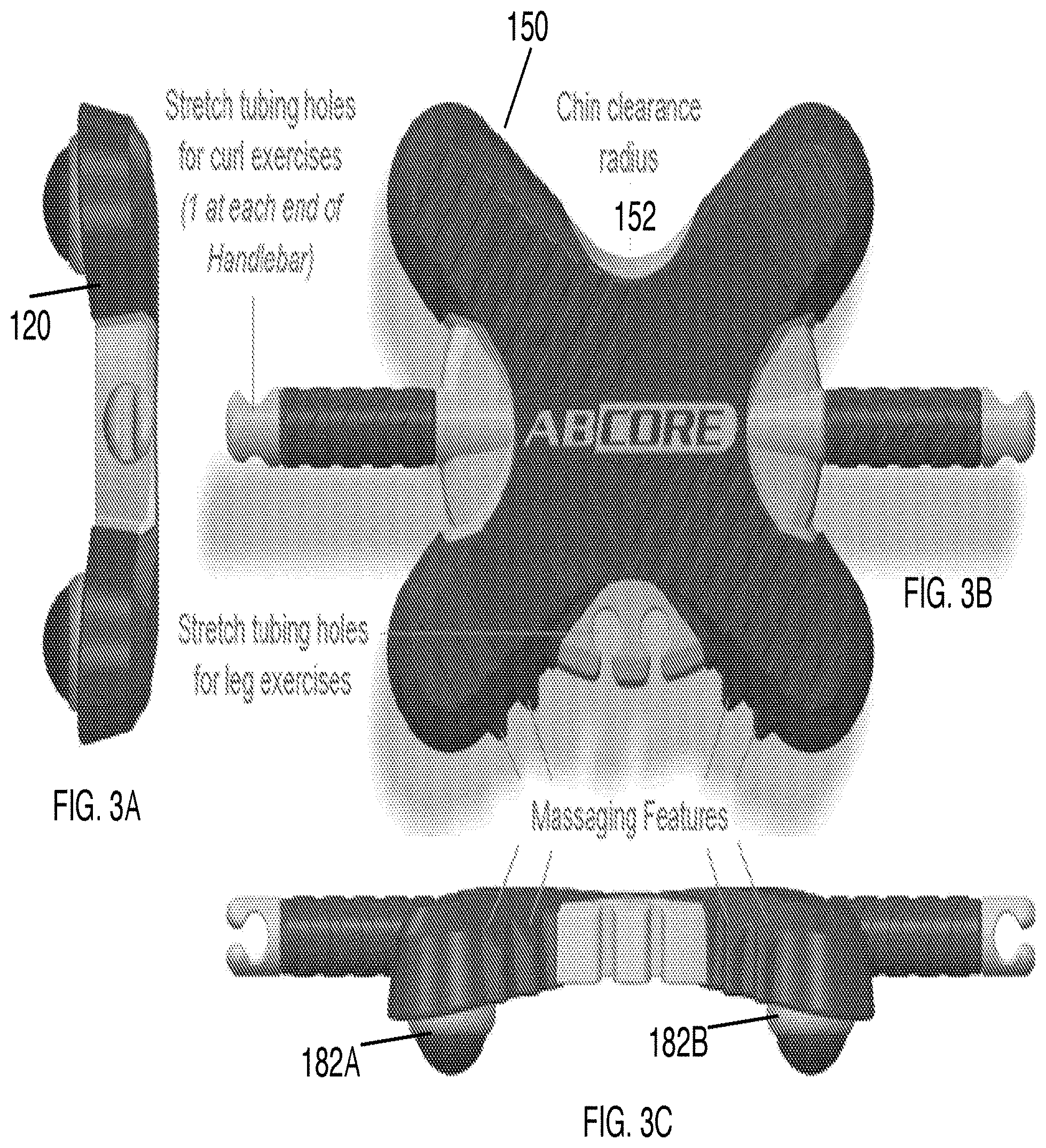
[0013] FIG. 3A is a left side view of the first example abdominal exercise device of FIG. 2.
[0014] FIG. 3B is a top view of the first example abdominal exercise device of FIG. 2.
[0015] FIG. 3C is a front side view of the first example abdominal exercise device of FIG. 2.
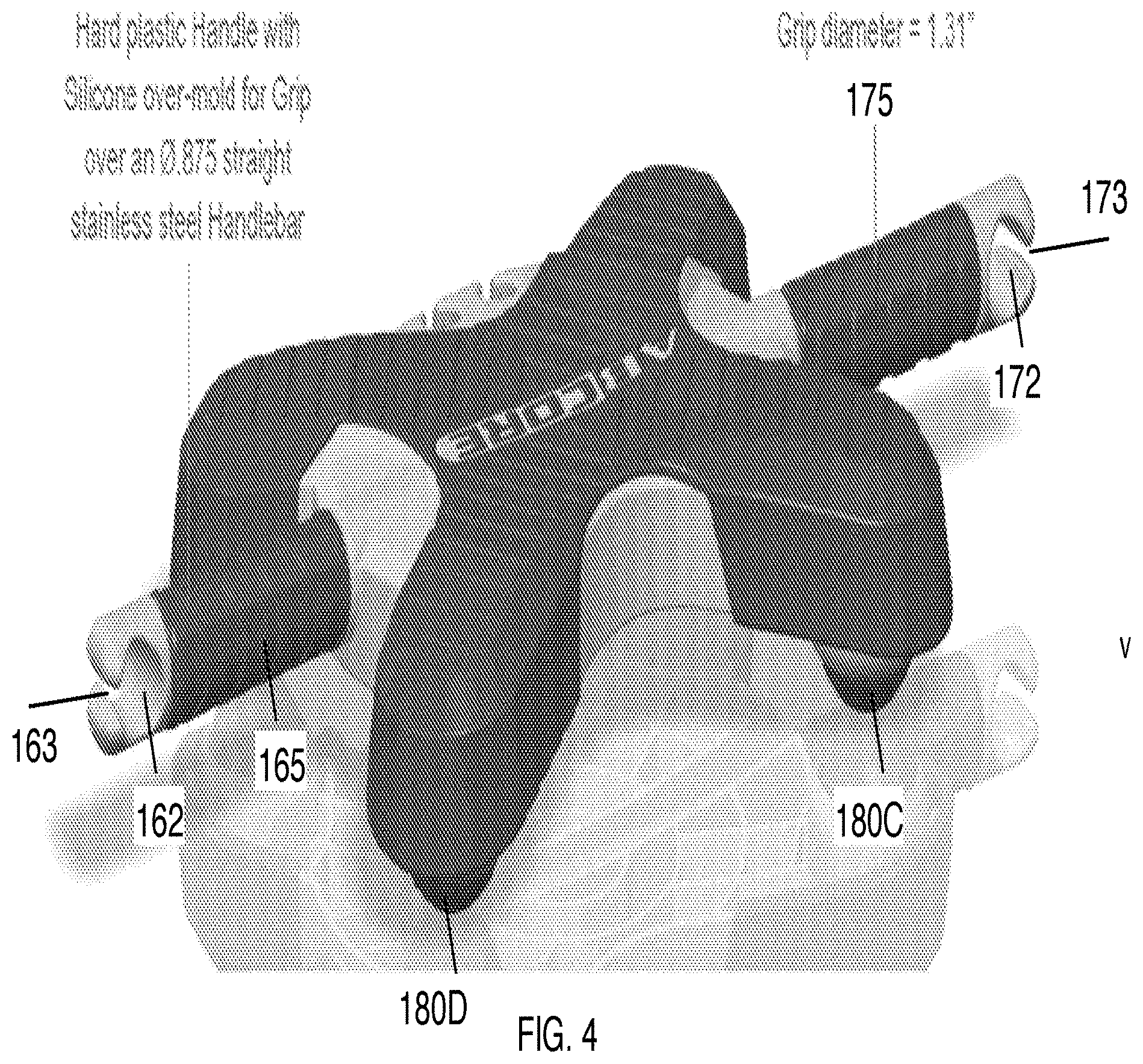
[0016] FIG. 4 is a rear perspective view of the first example abdominal exercise device of FIG. 2.
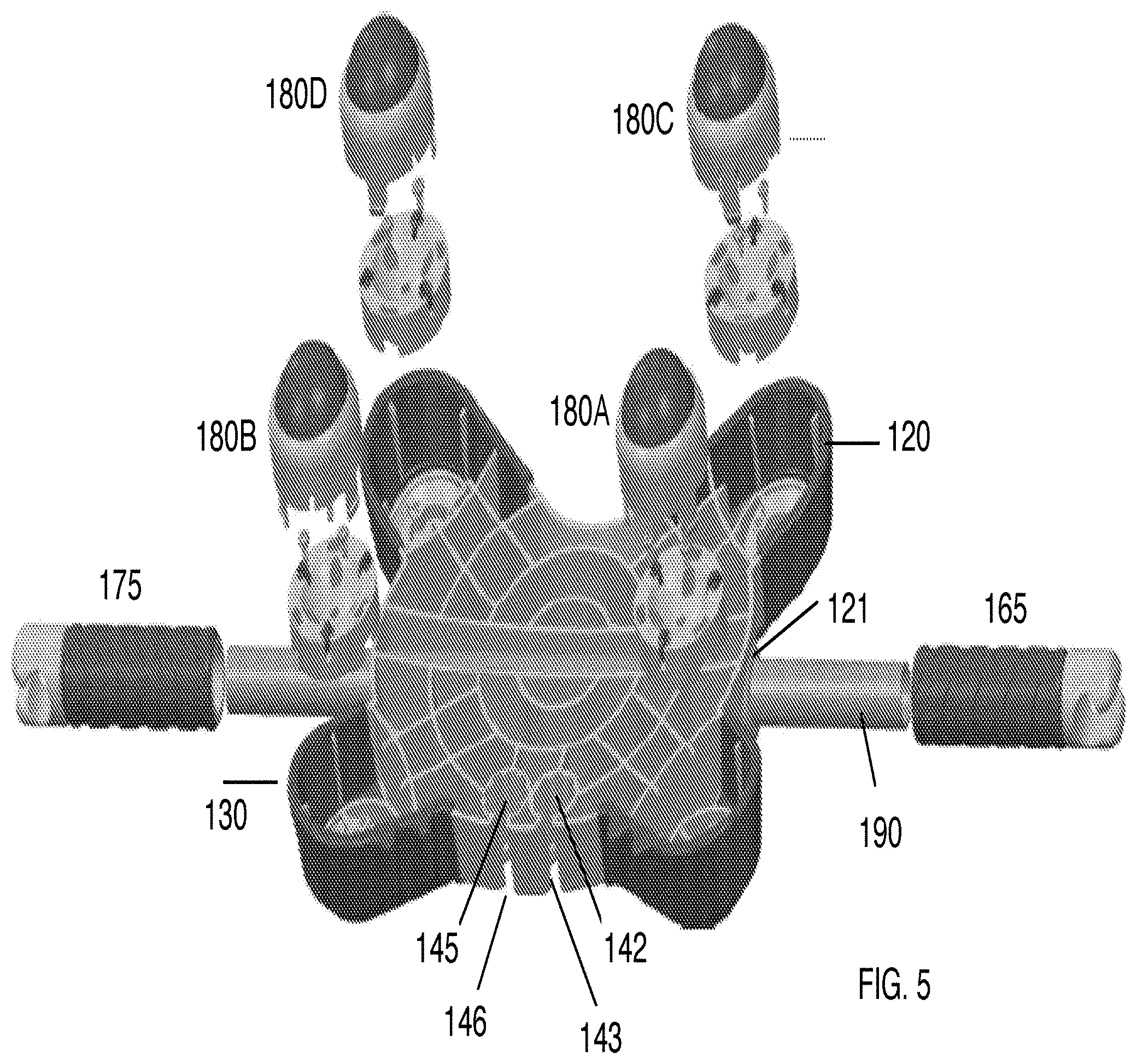
[0017] FIG. 5 is an exploded bottom perspective view of the first example abdominal exercise device of FIG. 2.
[0018] FIG. 6 is an exploded bottom perspective view of a caster assembly for the first example abdominal exercise device of FIG. 2.
[0019] FIG. 7 is an exploded top perspective view of a second example abdominal exercise device with a bent bar.
[0020] FIG. 8 is a top view of a third example abdominal exercise device.
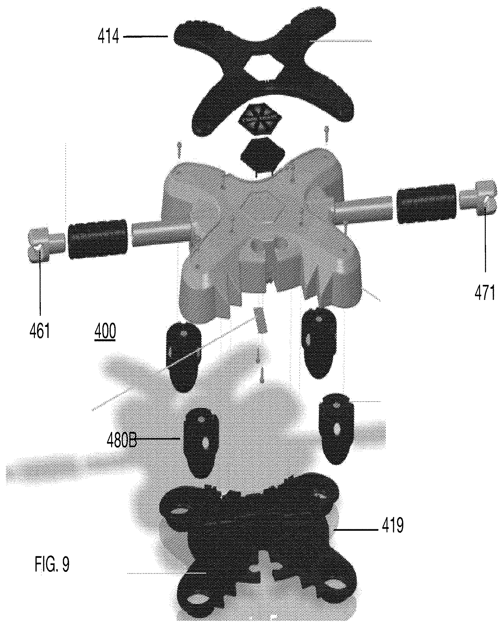
[0021] FIG. 9 is an exploded side view of the example abdominal exercise device of FIG. 8
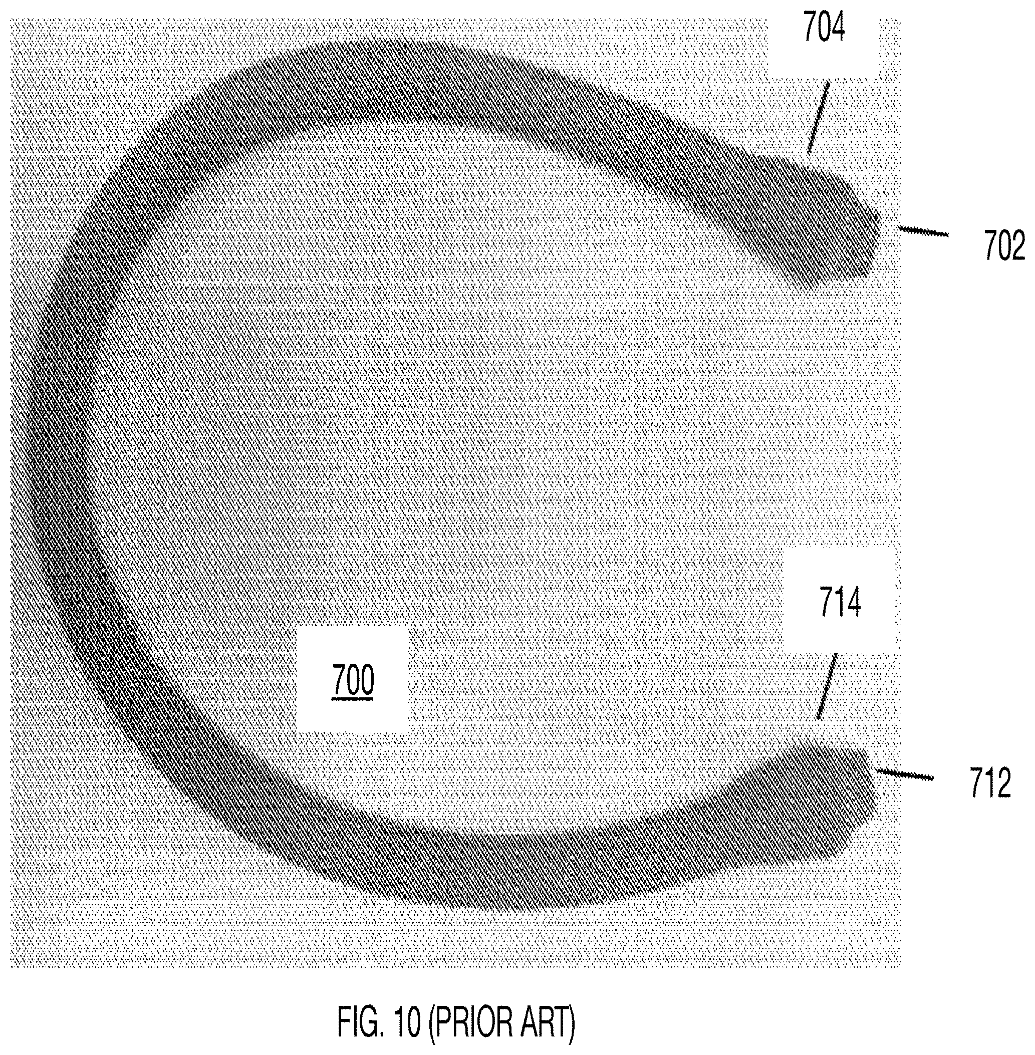
[0022] FIG. 10 (PRIOR ART) shows an example prior art elastic cord with internal plugs on each end.
[0023] FIG. 11 shows end portions of an example elastic cord with spaced apart cross sectional enlargement features positioned for attachment to handles or the front edge of the example abdominal exercise device.
[0024] FIG. 12A is a side perspective detailed view of an example tapered stop.
[0025] FIG. 12B is a side perspective detailed view of the tapered stop of FIG. 12A showing a hidden line view of a plug.
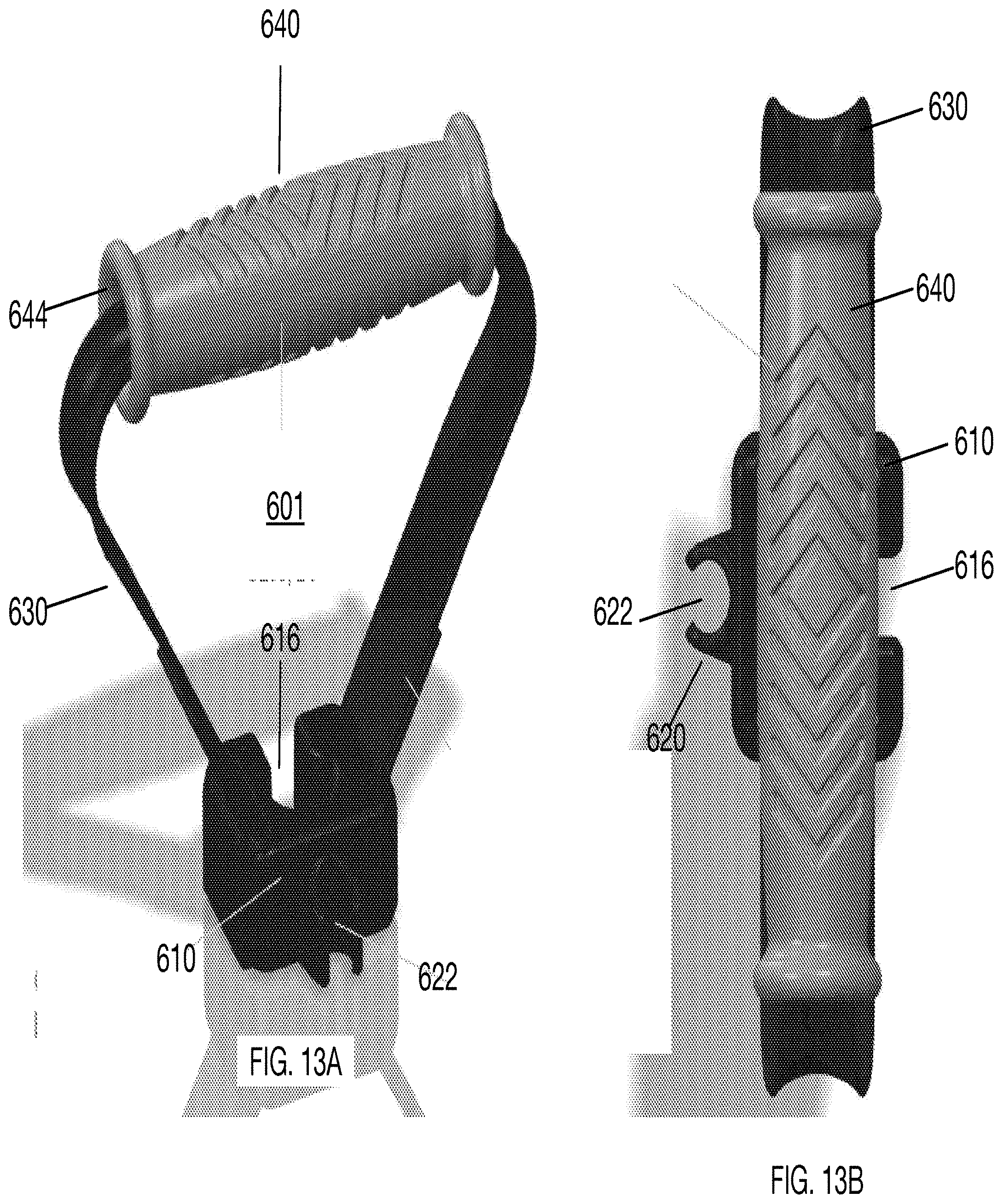
[0026] FIG. 13A is a side perspective view of an example handle with a cord retention element configured to accept a portion of an adjustable resistance elastic cord.
[0027] FIG. 13B is a top view of the handle of FIG. 13A.
[0028] FIG. 13C is a detailed front perspective view of a cord retention housing for the handle of FIG. 13A.
[0029] FIG. 14 is a detailed side view of the first end of the adjustable resistance elastic cord of FIG. 2A showing a pair of tapered stops with sleeves offset from the tapered plug portions for illustration.
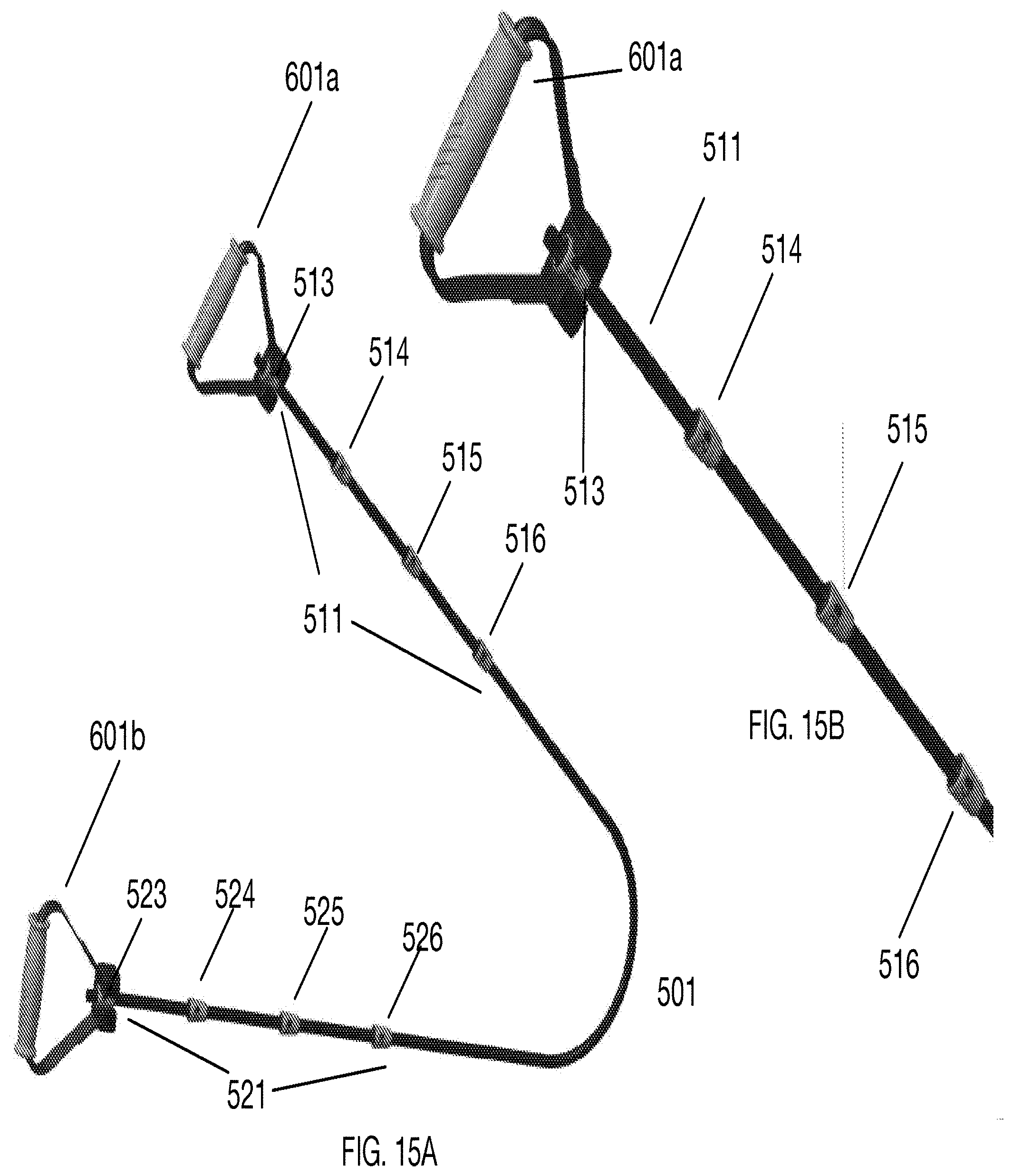
[0030] FIG. 15A is a side view of an example adjustable resistance elastic cord with handles and a plurality of tapered stops.
[0031] FIG. 15B is a detailed side view of the first end section of the adjustable resistance elastic cord of FIG. 15A.
DESCRIPTION OF EMBODIMENT
Abdominal Exercise Device with Straight Support Bar
Definitions
[0032] In this specification, the term "platform" means the portion of an exercise device configured to permit a user to place one or both feet; or one or both knees on the device so that the user can move the device with feet or knees. In some examples, the user may also stand on the platform, such as in a twisting exercise. The platform shape may be generally rectangular, polygonal, round or complex.
[0033] In this specification, the term "top surface" means the upper exposed surface of the platform when the device is positioned on a floor or other work area.
[0034] In this specification, the term "edge" refers to a circumferential portion of the device platform. The device may be generally rectangular, elliptical, circular, or have arbitrary shape. Edges may be straight, curved, or complex in shape.
[0035] In this specification, the terms "front edge" and "rear edge" are used for convenience to designate portions of the device, and the device can be oriented and operated in either direction when the handles are held, and can be pushed or pulled in any direction when the platform supports one or more foot or knee.
[0036] In this specification, the term "massage feature" means a protrusion configured to apply pressure on a thigh or other body area of a user.
[0037] In this specification, the term "chin indention" means a recessed area on a device that is configured to permit a user to conduct curling or other arm exercises by pulling the device closer to the user's chin.
[0038] In this specification, the term "handle" means a portion of an exercise device which is configured to permit a user to grasp and push or pull the device with a hand. In some examples, a handle is an elongated extension from or through the platform.
[0039] In this specification, the term "wheel, roller, or caster assembly" means an assembly which permits the exercise device to roll along a floor or other work area.
[0040] In this specification, the term "resistance element" means one or more elastic band, elastic cord, spring, or spring mechanism which provides a resistance to the moving the device away from a portion of the user's body or away from a fixed point. In this specification, the term resistance element refers to a device accessory that either increases the resistance of roller abdominal exercises or facilitates other exercises. The term does not refer to the adjustment of wheel, roller or caster friction, which may be provided independent of the device accessories.
[0041] In this specification, the term "elastic band or cord" means a cord, strap, or band of a single elastic material or composition, or having at least a middle portion of elastic material. For example, an elastic band or cord may have a fixed handle on one or more ends.
[0042] In this specification, the terms "cord exercises" or "elastic cord exercises" means exercises performed with one or more elastic cord, strap, or band.
[0043] In this specification, the terms "knot or cross sectional enlargement feature" or "stop element" mean a tied portion of a band cord, or strap; or a section of a band, cord, or strap having an enlarged cross-sectional area. The enlarged cross-sectional area may be formed of the same material as the band, cord, or strap, or may be formed by clamping gluing, welding, or otherwise affixing another material or element to the inside of a band, cord, or strap; to the outside of a band, cord, or strap; or to both the inside and outside of a band, cord, or strap.
[0044] In this specification, the term "resistance element attachment feature" means a feature provided on the abdominal exercise device, handle, surface attachment clamp, or other cord restraint device to permit attachment of a portion of an elastic cord or band. In some examples, this feature can be a slotted cord stop element receptacle that accepts a portion of the elastic cord or band, but restricts passage of a knot or other cross sectional enlargement feature on the elastic cord or band. In other examples, the attachment feature may be a ring which accepts a hook provided on the elastic cord or band. In other examples, other attachment features may be provided to mate with corresponding elements on the elastic cord or band.
[0045] In this specification, the term "cord foot attachment" means a strap, harness, or other device configured to be temporarily held by one or both feet while a cord, strap, or band is stretched relative to the device.
[0046] In this specification, the term "surface attachment clamp" means an element that is temporarily or permanently affixed to a wall, door frame, tree limb, article of furniture, or other surface than provides at least one cord retention feature to accept a selected knot or cross sectional enlargement feature while a user performs elastic cord exercises. A user may perform cord exercises at a desired adjustable cord or band strength by attaching a first selected knot or cross sectional enlargement feature, in proximity to a first end of a cord or band, to a first cord retention feature on the surface attachment clamp; and optionally attaching a second selected knot or cross sectional enlargement feature, in proximity to a second end of a cord or band, to a second cord retention feature on the surface attachment clamp.
[0047] FIG. 2 is a top perspective view of a first example abdominal exercise device 100 with a platform 110 having top surface grip traction features 112; a right handle 170; and a left handle 160. In this embodiment, the top surface is large enough to support two feet or knees in order to conduct various exercises. The handles are spaced apart so that the hands are positioned at a spacing that matches or approximates the distance between the user's shoulders in order to reduce twisting stresses on the shoulders during exercises.
[0048] Cord Retention Features
[0049] In this example, cord retention features are provided on both handles and the front edge of the platform. The front edge 140 has first front cord retention feature 141 comprising a cord stop element receptacle 142 and a cord retention slot 143; and a second front cord retention feature 144 comprising a cord stop element receptacle 145 and a cord retention slot 146. In this example, the cord retention features are examples of slotted attachment elements.
[0050] In another example, the front cord retention features 141 and 144 are rotated 90 degrees so that the elastic band or cords are aligned with the device. In other examples, the cord retention features may be set at different angles with respect to the platform.
[0051] A single looped resistance band may be configured with end portions secured in the two front cord retention features 141 and 144 so that the middle of the band may be held with the user's foot or feet while the device is used for curls and other exercises. In other examples, separate bands are provided, with one or more knots or other enlarged portions on the proximal ends, and a handle adapted to engage a hand or foot is provided on the distal ends.
[0052] Elastic bands and cords are examples of resistance elements. The cord retention features are one example of a resistance element attachment feature, and other methods of attaching a resistance element such as a cord or elastic band may be employed.
[0053] In this example, a plurality of massage features 147A, 147B, 148A, 148B are provided on the front edge so that the features may be used to provide pressure on a leg or other body area, such as to stimulate blood flow.
[0054] The rear edge 150 of the device has a chin indention 152 which permits the user to pull the device closer to the user's chin during elastic cord exercises.
[0055] Handles
[0056] FIG. 3A is a left side view of the first example abdominal exercise device 100. FIG. 3B is a top view of the first example abdominal exercise device 100. FIG. 3C is a front side view of the first example abdominal exercise device 100. The right handle 170 has a right hand grip 175, and a right handle cord retention feature 171 comprising a cord stop element receptacle 172 and a cord retention slot 173. An portion of an elastic cord may be inserted through the cord retention slot and into the cord stop element receptacle. The cord stop element receptacle is smaller than a knot or other stop feature provided on the cord. The left handle 160 has a left hand grip 165, and a left handle cord retention feature 161 comprising a cord stop element receptacle 162 and a cord retention slot 163.
[0057] FIG. 4 is a rear perspective view of the first example abdominal exercise device 100 showing the rear edge 150 with a chin indention 152. In this example, the right and left handles are formed by over-molding a silicon grip on a stainless steel bar that extends straight through the device. In one example, the handles have a grip diameter of 1.31 inches (3.3 cm).
[0058] Caster Assemblies
[0059] FIG. 5 is an exploded bottom perspective view of the first example abdominal exercise device 100 of FIG. 2. FIG. 6 is an exploded bottom perspective view of a caster assembly 180 for the first example abdominal exercise device 100. In this embodiment, four caster assemblies 180A, 180B, 180C, 180D are provided on the bottom of the device so that the device may be moved in any direction along a floor or other surface. The caster assemblies 180A, 180B, 180C, 180D include a caster base 181 with screw mount holes 182, and roller wheel slots 183. In this example, three roller wheels 185 support the device over a polymer or rubber ball 186 in a manner that provides low rolling friction. Each caster assembly has a caster cover 187 and snaps 188 to attach the cover to the platform. In this example, the polystyrene, other polymer, or rubber ball 186 has a diameter of about 2 inches (5.1 cm). The ball preferably has a relatively high hardness and a diameter of at least 1.5 (3.8 cm) inches, but smaller diameters may be used.
[0060] In other examples, other wheel or caster assemblies may be used, or the device may be provided with a low friction bottom sliding surface such as used in furniture moving disks.
[0061] The left side edge 120 has a left side rod hole 121; and the right side edge 130 has a right side rod hole 131. A metal rod 190 is inserted through the left side rod hole 121 and the right side rod hole 131.
[0062] In this example, the platform has a maximum length of about 12.5 inches (31.8 cm), and a maximum width of about 10.3 inches (26.2 cm). The handles have a floor clearance of about 1.5 (3.8 cm) inches.
[0063] The example exercises below illustrate the versatility of the exercise device for both cord exercises and abdominal exercises without a resistance element. The use of the device is not limited to these exercises.
Example--Knee Roll Out
[0064] The user takes an initial position on his knees with hands beneath the shoulders and facing downwards. The hands grasp handles of the abdominal exercise device. The user pushes the device away while keeping his arms extended. The torso is lowered as the device is pushed away. A first cycle is completed when the user pulls the device backwards to the initial position.
Example--V Roll Outs
[0065] V Roll Outs are similar to Knee Roll Outs, but put a greater emphasis on the oblique muscles. In this exercise, the user pushes forward to the right at about a 45 degree angle; returns to the starting position; then pushes forward to the right at about a 45 degree angle; and returns to the starting position.
Example--Knee Tuck
[0066] The abdominal exercise device platform is pushed backward and pulled forward by the user's feet. The user has an initial in a legs-extended position with toes of each foot placed on the top surface of device. The user's hands are placed outside of the torso and below the shoulders. The user pulls the device forward so that the user's knees are pulled closer to the hands. A first cycle is completed when the user pushes the device backwards and returns his legs to the extended position.
Example--Curl Exercises
[0067] The end portions of a single elastic band are attached to the device handles, and the user stands on middle portions of the band. In a standing position, the user's hands are facing upwards and lowered to waist level. The device is held by grasping device handles and the device is partially rotated upwards as the hands are raised to the chest. In other examples, the band ends need not be attached to the device handles, and the handles may be configured to permit the user to hold a portion of the band in each hand as the device is grasped. In other examples, two short bands may be provided, and the user can hold one end of each band by each foot, and attach the other end of each band to the device.
Example--Hands Down Curl Exercise
[0068] The end portions of a single elastic band are attached to the device handles, and the user stands on middle portions of the band. In a standing position, the user's hands are facing inwards and lowered to waist level. The device is held by grasping device handles and the device is partially rotated upwards as the hands are raised to the chest
Example--Twist Exercise
[0069] The user stands with both feet on the device with arms outstretched, then rotates hips to the left and back to the right. A first cycle is completed when the user returns to the initial position.
Example--One Foot Push Exercise
[0070] The user stands with right foot on the device, and left foot positioned behind and to the left of the device and pushes the device forward. The left leg is extended and the user is on the toes of left foot. The user repeats the movement with the left foot on the device.
Example--Sit and Curl Exercise
[0071] While seated, the user grasping device with hands facing upwards and feet on portions of the elastic cord and the user pulls the device to his chest.
Example--Abdominal Exercise Device with Bent Support Bar and Clamp
[0072] FIG. 7 is an exploded top perspective view of a second example abdominal exercise device 200 with a bent metal rod or tube; a platform 210 with top surface grip features 212; a right handle 270; and a left handle 260. In this example, a lower straight section of a bent metal rod or tube 290 is attached below the platform 210 with a rod clamp assembly comprising a front clamp 294 and a rear clamp 295. In other examples, the bent metal rod or tube 290 is held in place by a metal retention plate. The right handle has a right hand grip 275, and a right handle cord retention feature comprising a cord stop element receptacle 272 and a cord retention slot 273. An portion of an elastic cord may be inserted through the cord retention slot and into the channel. The cord stop element receptacle is smaller than a knot or other stop feature provided on the cord. The left handle has a left hand grip 265, and a left handle cord retention feature comprising a cord stop element receptacle 262 and a cord retention slot 263. In this example, the right and left handles are formed by over-molding a silicon grip on a a bent bar that is attached to the bottom surface of the platform. Four caster assemblies 280A, 280B (not shown), 280C, 280D are provided on the bottom of the device so that the device may be moved in any direction along a floor or other surface.
[0073] In this example, the front edge 240 has first front cord retention feature 241 comprising a cord stop element receptacle 242 and a cord retention slot 243; and a second front cord retention feature 244 comprising a cord stop element receptacle 245 and a cord retention slot 246. In another example, the front cord retention features 241 and 244 are rotated 90 degrees.
[0074] A single looped resistance band may be configured with end portions secured in the two front cord retention features 241 and 244 so that the middle of the band may be held with the user's foot or feet while the device is used for curls and other exercises.
Example--Abdominal Exercise Device with Cord Retention Slots
[0075] FIG. 8 is a top view of a third example abdominal exercise device 400 showing showing a left handle cord retention feature 461, a right handle cord retention feature 471, and a pair of cord retention features 441 and 444 on the edge of the platform. In this example, a pair of cord retention slots 454 are provided on the rear edge of the platform to secure extra elastic cord when stop elements are inserted into the cord retention features.
[0076] FIG. 9 is an exploded side view of the example abdominal exercise device of FIG. 8 showing the left handle cord retention feature 461, the right handle cord retention feature 471, a top pad 414, and a bottom cover plate 419.
Example Elastic Cord
[0077] FIG. 10 (PRIOR ART) shows an example prior art elastic cord 700 having a first end 702 and a second end 712. In this example, an elastic cord is provided with a a single cross sectional enlargement feature 704 in proximity to the first end 702; and a single cross sectional enlargement feature 714 in proximity to the first end 712. In this example, the cross sectional enlargement features are internal tapered plugs.
Example--Abdominal Exercise Device with Tapered Receptacle Cord Retention Elements
[0078] FIG. 11 shows end portions of an example elastic cord with spaced apart cross sectional enlargement features positioned for attachment to handles or the front edge of the example abdominal exercise device of FIG. 2. In this example, two end portions of a single cord, or end portions of two different cords may be attached to either receptacles A and B on the exercise device handles; or to receptacles C and D on the edge of the device platform.
[0079] In this example, the first end portion is shown positioned to be attached at position "A" to the left handle of the exercise device by inserting one of the first end portion's tapered stops 513, 514, or 515 into a left handle cord retention feature. The cord attachment is made by inserting a cord section below the selected tapered stop through the cord retention slot so that the tapered stop is positioned above the tapered receptacle; and then pulling the cord so that the tapered stop nests in the receptacle of the left handle cord retention feature. Since the tapered stop is larger than the tapered receptacle, the tapered stop cannot be pulled through the receptacle. A second cord end portion is shown positioned to be attached at "B" to the right handle of the exercise device by inserting one of the tapered stops 523, 524, or 525 into to the right handle cord retention feature in a similar manner.
[0080] In an alternative configuration, selected tapered stops on the first and second end portions of the cord may be attached to the exercise device front edge cord retention features as shown at "C" and "D" respectively. In this example, the front edge cord retention features are show as parallel to the front edge. In other examples, the cord retention features are provided orthogonal, or at other angles relative to the front edge.
[0081] In this example, the cross sectional enlargement features are formed by tapered stops created by inserting a tapered plug in a hollow cord, and then securing a tapered cover over the plug portion. FIG. 12A is a side perspective detailed view of an example tapered stop 523. In this example, the tapered stop has a tapered cover 550 with an engraved indicia 563. An upper lip 567 on the cover 550 prevents the cover from slipping down the cord. A pair of slots 568 are provided on the lip to permit the cover to be positioned over the plug. In this example, the lip is a reduced diameter circumferential slotted lip. FIG. 12B is a side perspective detailed view of the tapered stop 550 of FIG. 12A showing a hidden line view of a plug 540 with a larger upper portion 542 than lower portion 544.
[0082] In this example, three tapered stops are shown as being formed integral to each end of a single elastic cord. In other examples, two cords or bands may be used rather than a single band or cord. In other examples, other numbers of tapered stops may be provided on one or both ends of a cord.
[0083] In other examples, more than two cross sectional enlargement features may be provided on one or both ends of a cord or band, and those features can be formed integral to the elastic band or cord, or provided in another manner such as by tying knots in the band or cord, attaching end elements to an elastic band or cord where the end elements provide enlargement features, or by clamping or adhering beads or other elements to the band or cord at desired locations.
Example--Kit with Abdominal Exercise Device, Adjustable Resistance Cord, and Removable Handles
[0084] FIG. 13A is a side perspective view of an example handle 601 with a cord retention housing 610 configured to accept a portion of an adjustable resistance elastic cord. FIG. 13B is a top view of the handle of FIG. 12A. In this example, the handle 601 has a grip 640 with a central strap channel 644. A strap 630 has a first end 632 and a second end 634 secured to the cord retention housing 610, and a middle portion of the strap 630 is routed through the grip channel 644. In this example, the cord retention housing 610 has a single cord retention element 620 with a cord retention slot 622 and a tapered receptacle 626. The cord retention housing 610 also has an extra cord retention slot 616 so that when a tapered stop, such as 514, 515, or 516 is inserted into the tapered receptacle 626, a portion of the cord located between the selected the tapered stop and the end of the cord, may be wrapped over the cord retention housing 610 and inserted into the extra cord retention slot 616.
[0085] FIG. 13C is a detailed front perspective view of a cord retention housing 610 for the handle of FIG. 13A. In this example, the cord retention housing 610 includes a cord retention slot 622 and tapered receptacle 626. An extra cord retention slot 616 on the rear of the cord retention housing is not visible in this view. The first end 632 of strap 630 has been routed trough strap slot 628a and stitched, glued or otherwise secure to the strap; and the second end 634 of the strap has been routed trough strap slot 628b and secured to the strap. The cord retention housing 610 may be used in other cord retention devices such as a foot retention element or attachment clamp.
[0086] In other examples, the cord retention housing 610 may include a pair of cord retention elements 620 so that a single handle may secure tapered stops from two end portions of an elastic cord.
[0087] In other examples, the handle may be formed with a rigid material rather than a strap.
[0088] Adjustable Resistance Elastic Cord
[0089] FIG. 15A is a side view of an example adjustable resistance elastic cord 501 with a first end portion 511 and a second end portion 521. FIG. 15B is a detailed side view of the first end section 511 of the adjustable resistance elastic cord 501 of FIG. 15A. A first end of the cord is secured to a first handle 601a by inserting tapered stop 513 into the handle as described below. Other tapered stops 514, 515, and 516 are provided in the first end portion in order to permit the user to adjust the working resistance of the cord 501. In this example, a second end of the cord is secured to a second handle 601b by inserting tapered stop 523 into the handle. Other tapered stops 524, 525, and 526 are provided in the second end portion in order to permit the user to adjust the working resistance of the cord 501.
[0090] FIG. 14 is a detailed side view of the first end of the adjustable resistance elastic cord 501 of FIG. 15A showing a pair of tapered stops 513 and 514 with tapered covers 550a and 550b offset from the tapered plug portions for illustration. In this figure, the presence of the tapered plugs is shown by the expansion of the tubing over the tapered plugs at positions 540a and 540b so that the top portion 542 of the tapered plug has expanded the tubing wall more than the bottom portion 544 of the tapered plug. The tapered covers are secured over the tapered plug portions by moving the tapered covers toward the first end of the cord so that the top portion 552 of the tapered cover fits over the top portion 542 of the tapered plug; and the bottom portion 554 of the tapered cover fits over the tapered bottom portion 544 of the tapered plug.
[0091] In this example, the tapered covers have lips 567a and 567b which hold the sleeves over the tapered plug portions so that the sleeves do not slip down the cord. In this example, the tapered covers have indicia to permit a user to readily distinguish between the tapered stops. In this example, the tapered cover lips each have a pair of slots which permit the lips to be pulled over the plug portions of the cord.
Example--Single Variable Resistance Exercise Cord with Four Tapered Stops on Each End
[0092] In the example of FIGS. 15A, 15B, and 14, a variable resistance exercise cord has two end portions 511 and 512 with four spaced apart tapered stops on each end portion. Each tapered stop 513, 514, 515, 516, 523, 524, 525, and 526 has a tapered plug and a tapered cover with their narrower tapered portions of the internal plugs and tapered covers oriented toward the middle portion of the cord. This orientation permits tapered receptacles 626 on a handle, bar, abdominal exercise device, or other cord restraint device to secure the tapered stop as the cord is expanded; but to permit the tapered stop to be easily removed from the tapered receptacle when there is no tension on the cord. Insertion of the tapered stop is accomplished by positioning a downstream portion of the cord into the cord retention slot 622 and the tapered receptacle 626, and then pulling the cord until the tapered stop is seated in the tapered receptacle. Removal of the tapered stop is accomplished by relaxing cord tension, and then pushing or pulling the tapered stop until an un-stretched cord portion is positioned in the tapered receptacle 626, and then removing the un-stretched cord portion through the cord retention slot 622. In this example, adjacent tapered stop have the same spacing of about 6 inches (15.2 cm). In other examples, a variable spacing may be used, such as increasing the spacing of the tapered stop closer to an end of a cord.
[0093] In other examples, a different number of tapered stops may be placed on the variable resistance exercise cord.
[0094] In other examples, a plurality of tapered stops may be provided on first end of an adjustable resistance elastic cord, and a fixed handle may be provided on a second end of the cord.
Example--Abdominal Exercise Device with Sensors and Display
[0095] In this example, the abdominal exercise device has a display screen and sensors. The sensors may provide timing, repetition, or force and strain information to the user through the display. The display may also show an exercise sequence or exercise instructions. A wireless connection such as bluetooth connection to a phone, tablet, or other device may also be provided so that data from an exercise session can be logged. A smart phone or other application may be provided to analyze and report the logged data so that the user can track progress over time.
Example--Youth Version of Abdominal Exercise Device
[0096] In this example, a smaller device is provided for youth so that a young person can exercise alongside a parent.
[0097] It is to be understood that the specific embodiments and examples described above are by way of illustration, and not limitation. Various modifications may be made by one of ordinary skill, and the scope of the invention is as defined in the appended claims.
* * * * *
D00000
D00001
D00002
D00003
D00004
D00005
D00006
D00007
D00008
D00009
D00010
D00011
D00012

D00013
D00014

D00015

D00016
XML
uspto.report is an independent third-party trademark research tool that is not affiliated, endorsed, or sponsored by the United States Patent and Trademark Office (USPTO) or any other governmental organization. The information provided by uspto.report is based on publicly available data at the time of writing and is intended for informational purposes only.
While we strive to provide accurate and up-to-date information, we do not guarantee the accuracy, completeness, reliability, or suitability of the information displayed on this site. The use of this site is at your own risk. Any reliance you place on such information is therefore strictly at your own risk.
All official trademark data, including owner information, should be verified by visiting the official USPTO website at www.uspto.gov. This site is not intended to replace professional legal advice and should not be used as a substitute for consulting with a legal professional who is knowledgeable about trademark law.