A Modular Seating System And A Seating Unit
GEVA; Zeev
U.S. patent application number 16/086178 was filed with the patent office on 2020-09-24 for a modular seating system and a seating unit. The applicant listed for this patent is LAVI FURNITURE INDUSTRIES COOPERATIVE AGRICULTURAL SOCIETY LTD. Invention is credited to Zeev GEVA.
| Application Number | 20200297121 16/086178 |
| Document ID | / |
| Family ID | 1000004916057 |
| Filed Date | 2020-09-24 |


View All Diagrams
| United States Patent Application | 20200297121 |
| Kind Code | A1 |
| GEVA; Zeev | September 24, 2020 |
A MODULAR SEATING SYSTEM AND A SEATING UNIT
Abstract
A seating unit of a modular seating system, said seating unit comprising: a first lateral member comprising a first mounting arrangement; a second lateral member opposing said first lateral member and comprising a second mounting arrangement; a seat support member having a longitudinal support axis extending through said first lateral member and said second lateral member; and a seat articulated to said seat support member; wherein said first mounting arrangement is configured for coupling to said second mounting arrangement of a second lateral member of a neighboring identical seating unit, so as to attach said seating unit and said neighboring seating unit to each other; and wherein said seat support member has a first end associated with said first lateral member and an opposite second end associated with said second lateral member.
| Inventors: | GEVA; Zeev; (Kiryat Ata, IL) | ||||||||||
| Applicant: |
|
||||||||||
|---|---|---|---|---|---|---|---|---|---|---|---|
| Family ID: | 1000004916057 | ||||||||||
| Appl. No.: | 16/086178 | ||||||||||
| Filed: | March 13, 2017 | ||||||||||
| PCT Filed: | March 13, 2017 | ||||||||||
| PCT NO: | PCT/IL2017/050315 | ||||||||||
| 371 Date: | September 18, 2018 |
| Current U.S. Class: | 1/1 |
| Current CPC Class: | A47C 11/005 20130101; A47C 7/56 20130101; A47C 7/407 20130101 |
| International Class: | A47C 11/00 20060101 A47C011/00; A47C 7/56 20060101 A47C007/56; A47C 7/40 20060101 A47C007/40 |
Foreign Application Data
| Date | Code | Application Number |
|---|---|---|
| Apr 5, 2016 | IL | 244917 |
Claims
1-43. (canceled)
44. A seating unit for a modular seating system, said seating unit comprising: a first lateral member including a first mounting arrangement; a second lateral member opposing said first lateral member and including a second mounting arrangement; a seat support member having a longitudinal support axis extending through said first lateral member and said second lateral member; and a seat articulated to said seat support member; wherein said first mounting arrangement is configured for coupling to said second mounting arrangement of a second lateral member of a neighboring identical seating unit, so as to attach said seating unit and said neighboring identical seating unit to each other; and wherein said seat support member has a first end associated with said first lateral member and an opposite second end associated with said second lateral member.
45. The seating unit of claim 44, wherein said first mounting arrangement includes a protruding element, and said second mounting arrangement includes a recessed element configured for linking with a protruding element of the neighboring identical seating unit.
46. The seating unit of claim 44, wherein each of the first lateral member and the second lateral member is L-shaped and includes a seat portion with a seat axis extending along a length thereof, and a back portion with a back axis extending along a length thereof and disposed at an angle with respect to said seat main axis.
47. The seating unit of claim 46, wherein the seat portion and the back portion are substantially flat and coplanar.
48. The seating unit of claim 46, further comprising: at least one back support member and a back articulated thereto; wherein said back support member extends between the back portions of the first lateral member and the second lateral member; and wherein the seat support member extends between the seat portions of the first lateral member and the second lateral member.
49. The seating unit of claim 48, wherein the back support member has two opposing back flange members disposed at ends thereof for attaching the back support member to the first lateral member and the second lateral member.
50. The seating unit of claim 44, wherein the first mounting arrangement is configured for coupling to a first vertical leg of the modular seating system, and the second mounting arrangement is configured for coupling to a second vertical leg of the modular seating system for positioning the modular seating system over a floor.
51. A modular seating system, comprising: two or more neighboring identical seating units, each of said two or more neighboring identical seating units including: a first lateral member including a first mounting arrangement; a second lateral member opposing said first lateral member and including a second mounting arrangement; a seat support member having a longitudinal support axis extending through said first lateral member and said second lateral member; and a seat articulated to said seat support member; wherein said first mounting arrangement of one of said two or more neighboring identical seating units is configured for coupling to said second mounting arrangement of another one of said two or more neighboring identical seating units, so as to attach said two or more neighboring identical seating units to each other and cause the longitudinal support axes of the two or more neighboring identical seating units to coextend with each other; and wherein said seat support member has a first end associated with said first lateral member and an opposite second end associated with said second lateral member.
52. The modular seating system of claim 51, wherein said first mounting arrangement includes a protruding element, and said second mounting arrangement includes a recessed element configured for linking with a protruding element of a neighboring seating unit of the two or more neighboring identical seating units.
53. The modular seating system of claim 51, wherein both of said first mounting arrangement and said second mounting arrangement are either recessed elements or protruding elements, and configured to be linked to a corresponding mounting arrangement of a neighboring seating unit of said two or more neighboring identical seating units by a connector element.
54. The modular seating system of claim 51, wherein the seat support member, the first mounting arrangement, and the second mounting arrangement coextend with each other along said longitudinal support axis.
55. The modular seating system of claim 51, wherein the first mounting arrangement and the second mounting arrangement are formed at outside faces of the respective first lateral member and the second lateral member of the two or more neighboring identical seating units.
56. The modular seating system of claim 51, wherein each of the first lateral member and the second lateral member is L-shaped and includes a seat portion with a seat axis extending along a length thereof, and a back portion with a back axis extending along a length thereof and disposed at an angle with respect to said seat main axis.
57. The modular seating system of claim 56, wherein the seat portion and the back portion are substantially flat and coplanar.
58. The modular seating system of claim 56, further comprising: at least one back support member and a back articulated thereto; wherein said back support member extends between the back portions of the first lateral member and the second lateral member; and wherein the seat support member extends between the seat portions of the first lateral member and the second lateral member.
59. The modular seating system of claim 58, further comprising a back plate to which backs of the two or more neighboring identical seating units are connectable.
60. A method for assembling a modular seating system, the method comprising: providing two neighboring identical seating units, each of the two neighboring identical seating units including: a first lateral member including a first mounting arrangement; a second lateral member opposing said first lateral member and including a second mounting arrangement; a seat support member having a longitudinal support axis extending through said first lateral member and said second lateral member; and a seat articulated to said seat support member; and coupling said first mounting arrangement of one of the two neighboring identical seating units to said second mounting arrangement of another one of said two neighboring identical seating units, thereby attaching the two neighboring identical seating units to each other and causing the longitudinal support axes of the two neighboring identical seating units to coextend with each other; wherein said seat support member has a first end associated with said first lateral member and an opposite second end associated with said second lateral member.
61. The method of claim 60, further comprising: providing said first mounting arrangement with a protruding element and said second mounting arrangement with a recessed element; and linking with said protruding element of one of the two neighboring identical seating units with said recessed element of another one of said two neighboring identical seating units by introducing the protruding element into the recessed element.
62. The method of claim 60, further comprising: providing a connector element having a first connector end and a second connector end; and introducing the first connector end into the first mounting arrangement of one the two neighboring identical seating units and the second connector end into the second mounting arrangement of another one of said two neighboring identical seating units.
63. The method of claim 60, further comprising: providing said modular seating system with a first vertical leg and a second vertical leg; mounting said first vertical leg to the first mounting arrangement of one of the extreme of the two neighboring identical seating units; and mounting said second vertical leg to the second mounting arrangement of another one of the two neighboring identical seating units.
Description
TECHNOLOGICAL FIELD
[0001] The presently disclosed subject matter is related to the field of seating systems having a plurality of seating units arranged side-by-side. In particular, the presently disclosed subject matter is related to the field of modular seating systems.
BACKGROUND
[0002] There are many uses for seating systems in which two or more seating units are mounted together side-by-side. Such seating systems can be found in institutions of all kinds such as airports, hospitals, theaters, houses of prayers (e.g., synagogues, churches, etc.), and waiting rooms of doctors, lawyers, and other professionals. One reason for their popularity compared to using a plurality of single seating units is they remain arranged in a given configuration, they tend to take up less floor space, and they can have fewer floor supports.
[0003] For example, U.S. Pat. No. 5,431,479 discloses a tandem chair assembly that comprises a frame and a plurality of seating units. The frame comprises a pair of opposed legs and a horizontal beam extending between and attached to the end legs. The seating units comprise a seat support section and a back support section, positioned side-by-side between the legs with their fronts supported on the beam. Seat connection plates secure the front of the seat support section of each seating unit to the horizontal beam. In addition brackets are used for rigidly connecting each leg to the back support section of the seating unit next to the leg. Further, the back support sections of each adjacent pair of seating units are rigidly connected together, and the seat support section and back support section are maintained at right angles by means of right angle struts that double as arm rests.
[0004] According to another example, U.S. Pat. No. 5,306,072 discloses a modular article of furniture which has a right hand element and a left hand element, each being a rigid U-shaped arch with a pair of downwardly-extending legs, and a bight joining the legs. A pair of parallel shear members are integrally and rigidly connected to each of the legs, the members of each pair being one above the other. The shear members are joined by a splice, and an interconnecting member joins them for in-plane stability against tilting of the right hand element and left hand element.
General Description
[0005] According to a first aspect of the presently disclosed subject matter, there is provided a seating unit of a modular seating system, said seating unit comprising:
[0006] a first lateral member comprising a first mounting arrangement;
[0007] a second lateral member opposing said first lateral member and comprising a second mounting arrangement;
[0008] a seat support member having a longitudinal support axis extending through said first lateral member and said second lateral member; and
[0009] a seat articulated to said seat support member;
[0010] wherein said first mounting arrangement is configured for coupling to said second mounting arrangement of a second lateral member of a neighboring identical seating unit, so as to attach said seating unit and said neighboring seating unit to each other.
[0011] According to a second aspect of the presently disclosed subject matter, there is provided a modular seating system comprising two or more neighboring identical seating units, each of said seating units comprising:
[0012] a first lateral member comprising a first mounting arrangement;
[0013] a second lateral member opposing said first lateral member and comprising a second mounting arrangement;
[0014] a seat support member having a longitudinal support axis extending through said first lateral member and said second lateral member; and
[0015] a seat articulated to said seat support member;
[0016] wherein said first mounting arrangement of one of said seating units is configured for coupling to said second mounting arrangement of another one of said seating units, so as to attach said seating units to each other and cause the longitudinal support axes of the seating units to coextend with each other.
[0017] The modular seating system according to the first and the second aspects of the presently disclosed subject matter is structured of neighboring identical seating units, attached to each other in such a manner that their seat support members are forming together a rigid longitudinal structure extending along the longitudinal support axis of the seating system. The modular seating system can further comprise two system support members (e.g., vertical legs), one of which is connected to a first extreme seating unit disposed at one end of the seating system and another one of which is connected to a second extreme seating unit, disposed at another end of the seating system. The seating system support members are configured to be disposed over a floor or another surface. The rigid longitudinal structure provides support for the seating system and substantially prevents bending of the seating system upon application of an external load perpendicularly to the longitudinal support axis (e.g., weight of one or more users seating on one or more seating units of the seating system). The rigid longitudinal structure can provide stability to the seating system when the external load is applied thereon, without the necessity to connect or use one or more additional system support members (e.g., additional vertical legs) extending from intermediate seating units (i.e., seating units other than the extreme seating units) to the surface over which the seating system is disposed.
[0018] Due to the structure of the seating units, and in particular the compact structure of their seat support members and their connectivity to each other, while providing the required stability and resistance to deformation of the seating system, the number of the seating units is flexible and can be determined in accordance with the available space or other requirements at the installation site of the seating system. For example, the number of the seating units can vary between two to six or seven and even more seating units in a single seating system, without using the additional system support members. The compact structure of seat support members, and the fact that they extend along the longitudinal support axis, allows reducing weight of the entire support structure disposed under the seat, while preserving its ability to withstand the external load applied on the seating unit.
[0019] Any one or more of the following features, designs and configurations can be incorporated in the seating system and the seating units of the first and the second aspects of the presently disclosed subject matter, independently or in combination thereof:
[0020] The first mounting arrangement can comprise a protruding element and the second mounting arrangement can comprise a recessed element configured for linking with a protruding element of the neighboring seating unit. Alternatively, both the first mounting arrangement and the second mounting arrangement can be either recessed elements or protruding elements, configured to be linked to a corresponding mounting arrangement of the neighboring seating unit by a connector element.
[0021] The seat support member, the first mounting arrangement and the second mounting arrangement can coextend with each other along the longitudinal support axis.
[0022] The first mounting arrangement and the second mounting arrangement can be formed at outside faces of the respective first lateral member and the second lateral member of the seating unit.
[0023] Each of the first lateral member and the second lateral member can be L-shaped and can comprise a seat portion with a seat axis extending along its length, and a back portion with a back axis extending along its length and disposed at an angle with respect to the seat main axis.
[0024] The seat portion and the back portion can be substantially flat and coplanar.
[0025] The seating unit can further comprise at least one back support member and a back articulated thereto. The back support member can extend between the back portions of the first lateral member and the second lateral member. The seat support member can extend between the seat portions of the first lateral member and the second lateral member.
[0026] The back support member can have two opposing back flange members disposed at ends thereof for attaching the back support member to the first lateral member and the second lateral member.
[0027] The seat support member can have two opposing seat flange members disposed at ends thereof for attaching the seat support member to the first lateral member and the second lateral member.
[0028] The seat support member can be bar-shaped and the seat can be pivotally displaceable about the seat support member between a deployed position and an undeployed position.
[0029] The first mounting arrangement can be configured for coupling to the first system support member, and the second mounting arrangement can be configured for coupling to the second system support member for positioning the seating system over a floor or another surface.
[0030] The seating system support members can be a first vertical leg and a second vertical leg, both configured. The first vertical leg can be coupled to the first mounting arrangement of the first extreme seating unit, and the second vertical leg can be coupled to the second mounting arrangement of the second extreme seating unit.
[0031] The seating system can comprise a back plate to which backs of the seating units are connectable. The back plate can provide further support to the entire seating system, for preventing the seating system from bending upon application of an external load perpendicularly to the longitudinal support axis. The back plate can improve the stability of the seating system, and can assist the rigid longitudinal structure to withstand the external load applied perpendicularly to the longitudinal support axis.
[0032] According to a third aspect of the presently disclosed subject matter, there is provided a method for assembling the modular seating system of the second aspect, comprising steps of:
[0033] a. providing two neighboring identical seating units, each comprising: a first lateral member comprising a first mounting arrangement; a second lateral member opposing the first lateral member and comprising a second mounting arrangement; a seat support member having a longitudinal support axis extending through the first lateral member and the second lateral member; and a seat articulated to said seat support member; and
[0034] b. coupling the first mounting arrangement of one of the seating units to the second mounting arrangement of another one of the seating units, thereby attaching the seating units to each other and causing the longitudinal support axes of the seating units to coextend with each other.
[0035] The method can further comprise steps of: providing the first mounting arrangement with a protruding element and the second mounting arrangement with a recessed element; and linking with the protruding element of one of the seating units with the recessed element of another one of the seating units by introducing the protruding element into the recessed element.
[0036] The method can further comprise steps of: providing a connector element having a first connector end and a second connector end; and introducing the first connector end into the first mounting arrangement of one the seating units and the second connector end into the second mounting arrangement of another one of the seating units.
[0037] The method can further comprise steps of: providing the seating system with a first vertical leg and a second vertical leg; and mounting the first vertical leg to the first mounting arrangement of one of the extreme seating units, and mounting the second vertical leg to the second mounting arrangement of another one of the seating units.
[0038] According to a fourth aspect of the presently disclosed subject matter, there is provided a seating unit comprising:
[0039] two opposing lateral members;
[0040] a seat support member extending between said lateral members; and
[0041] a modular seat comprising: a seat flat portion, a first bearing member and a second bearing member; at least one of said first bearing member and said second bearing member being mounted to the seat flat portion, and said first bearing member and said second bearing member at least partially embracing said seat support member therebetween, forming together a bearing assembly allowing pivotal displacement of the seat about to the seat support member between a deployed position and an undeployed position.
[0042] According to a fifth aspect of the presently disclosed subject matter, there is provided a method for assembling the seating unit of the fourth aspect, comprising steps of:
[0043] a. providing a seating unit comprising: two opposing lateral members; a seat support member extending between said lateral members; a modular seat comprising: a seat flat portion, a first bearing member and a second bearing member; at least one of said first bearing member and said second bearing member is mounted to the seat flat portion; and
[0044] b. at least partially embracing said seat support member by said first bearing member and said second bearing member, thereby forming a bearing assembly allowing pivotal displacement of the seat about to the seat support member between a deployed position and an undeployed position.
[0045] The modular seat of the fourth and the fifth aspects of the presently disclosed subject matter is configured to be modularly installed on the seat support member. For example, in a configuration in which the first bearing member is mounted to a flat portion, they both (with additional elements related thereto, if any exist) constitute a first part of the modular seat, and the second bearing member (with additional elements related thereto, if any exist) constitutes a second part of the modular seat. When the modular seat is disassembled, these first and second parts are provided separately from each other. During assembly of the modular seat on the seat support member, the first and the second parts can be attached to each other with the seat support member disposed therebetween, thereby embracing the seat support member and forming together a bearing assembly allowing pivotal displacement of the seat about to the seat support member between a deployed position and an undeployed position.
[0046] According to an alternative example, in a configuration in which the second bearing member is mounted to a flat portion, they both (with additional elements related thereto, if any exist) constitute a first part of the modular seat, and the first bearing member (with additional elements related thereto, if any exist) constitutes a second part of the modular seat. When the modular seat is disassembled, these first and second parts are provided separately from each other. During assembly of the modular seat on the seat support member, the first and the second parts are attached to each other with the seat support member disposed therebetween, thereby embracing the seat support member and forming together a bearing assembly allowing pivotal displacement of the seat about to the seat support member between a deployed position and an undeployed position. At the deployed position, a user can sit on the seating unit.
[0047] At least a portion of the second bearing member can be disposed at the rear of the seat and can be configured with a weight member configured to cause the seat to normally assume its deployed position. According to this configuration, the modular seat can thus be provided without any springs or any other compression or tension elements responsible for causing the seat to automatically revert to its normally deployed position. It is known that such elements experience physical deterioration over time. Therefore, the configuration of the modular seat with the weight member simplifies its structure and improves its reliability over time.
[0048] At least one of the first bearing member and the second bearing member can have a rounded internal wall. According to a particular example, both the first bearing member and the second bearing member have a rounded internal wall, complementary to each other and to a rounded wall portion of seat support member, which they embrace.
[0049] The first bearing member can be provided with a first cover member and the second bearing member can be provided with a second cover member configured to be mounted to the first cover member, to cause the first bearing member and the second bearing member to embrace the seat support member. The step (b) of the method according to the fifth aspect can thus be performed by mounting the second cover member to the first cover member.
[0050] The first cover member can have a receiving space for accommodating the second cover.
[0051] The weight member can be attached to an internal wall of the second cover member.
[0052] The seat of the first, second and third aspects of the presently disclosed subject matter can be the modular seat of the fourth and fifth aspects, with some or all possible variations and configurations thereof.
[0053] According to a sixth aspect of the presently disclosed subject matter, there is provided a seating unit comprising:
[0054] two opposing lateral members, each configured with a hand rest receiving element;
[0055] a seat extending between said lateral members;
[0056] a back extending between said lateral members and comprising two opposing side blocking elements disposed at least partially in front of said hand rest receiving elements; and
[0057] a hand rest having a hand rest connector connectable to one of said hand rest receiving elements;
[0058] wherein said side blocking elements are selectively convertible between a blocking state in which they obstruct access of said hand rest connector to the respective hand rest receiving element, and an unblocking state in which said access is allowed for mounting said hand rest connector to the respective hand rest receiving element.
[0059] According to a seventh aspect of the presently disclosed subject matter, there is provided a method for mounting a hand rest to a seating unit of the sixth aspect, comprising steps of:
[0060] a. providing a seating unit comprising: two opposing lateral members, each configured with a hand rest receiving element; a seat extending between said lateral members; a back extending between said lateral members and configured with two opposing side blocking elements disposed at least partially in front of said hand rest receiving elements; and a hand rest having a hand rest connector;
[0061] b. converting one of said side blocking elements from a blocking state in access of said hand rest connector to the respective hand rest receiving element is obstructed, to an unblocking state in which said access is allowed; and
[0062] c. mounting said hand rest connector to the respective hand rest receiving element.
[0063] The seating unit according to the sixth and seventh aspect allows selectively mounting a hand rest to the seating unit, upon demand. For example, when there is a need to add a hand rest to the seating unit, a respective side blocking element can be converted from its blocking state to its unblocking state, and the hand rest connector can be mounted to the respective hand rest receiving element. This hand rest can also be removed from the seating unit, and the respective side blocking element can afterwards be converted from its unblocking state to its blocking state.
[0064] The hand rest receiving elements can be formed as recesses, and the hand rest connector can be formed as a protrusion configured to be received in each of the recesses.
[0065] At least at their blocking state, the blocking elements can be mounted to the back by weakened areas allowing disconnecting of the blocking elements from the back at their unblocking state.
[0066] The step (b) can be performed by disconnecting said one of the blocking elements from the back.
[0067] The seat unit of the first, second, third, fourth and fifth aspects of the presently disclosed subject matter can be the seat unit of the sixth and seventh aspects, with some or all possible variations and configurations thereof.
BRIEF DESCRIPTION OF THE DRAWINGS
[0068] In order to better understand the subject matter that is disclosed herein and to exemplify how it may be carried out in practice, embodiments will now be described, by way of non-limiting examples only, with reference to the accompanying drawings, in which:
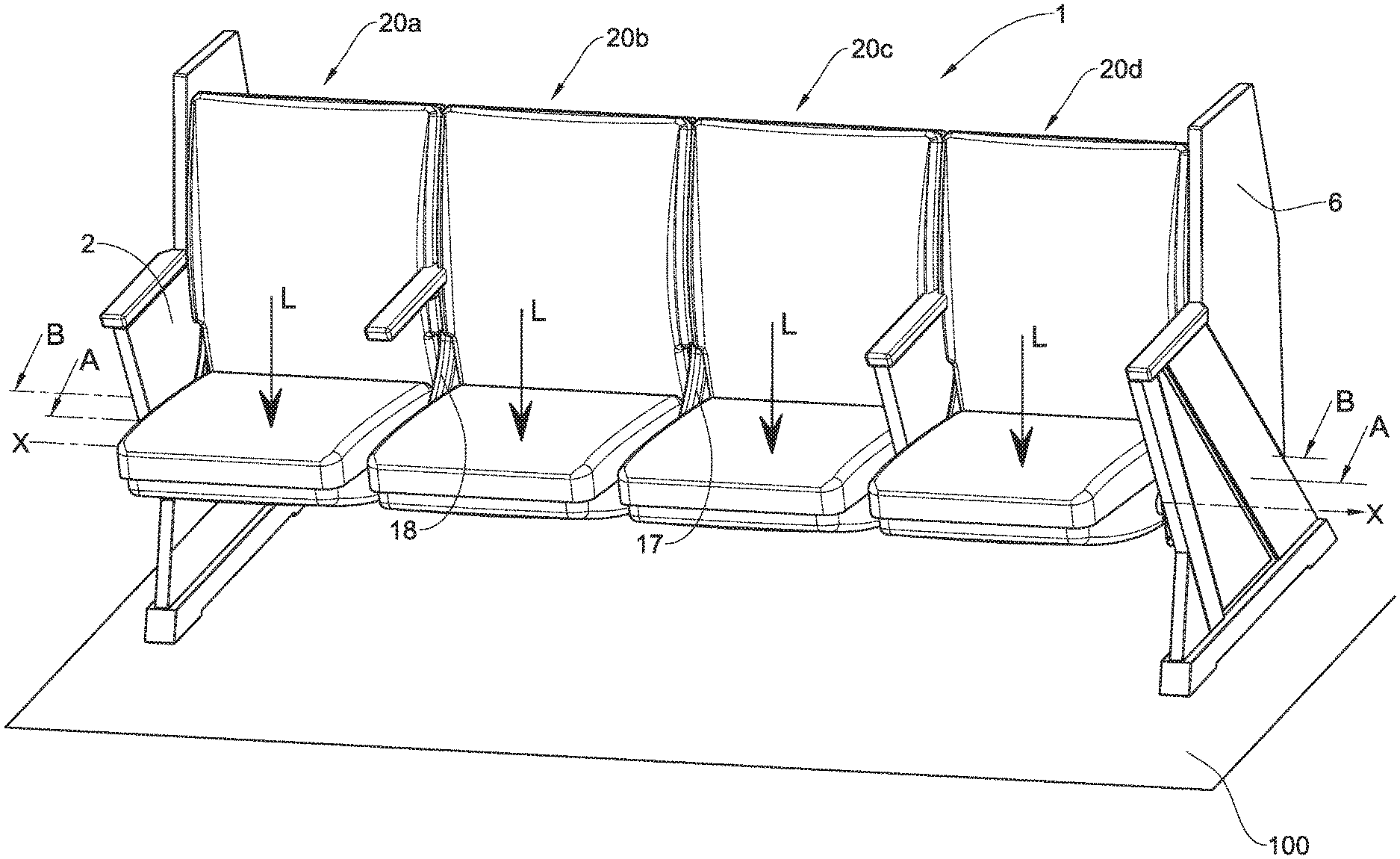
[0069] FIG. 1A is a front isometric view of a modular seating system according to one example of the presently disclosed subject matter;
[0070] FIG. 1B is a rear isometric view of the modular seating system of FIG. 1A;
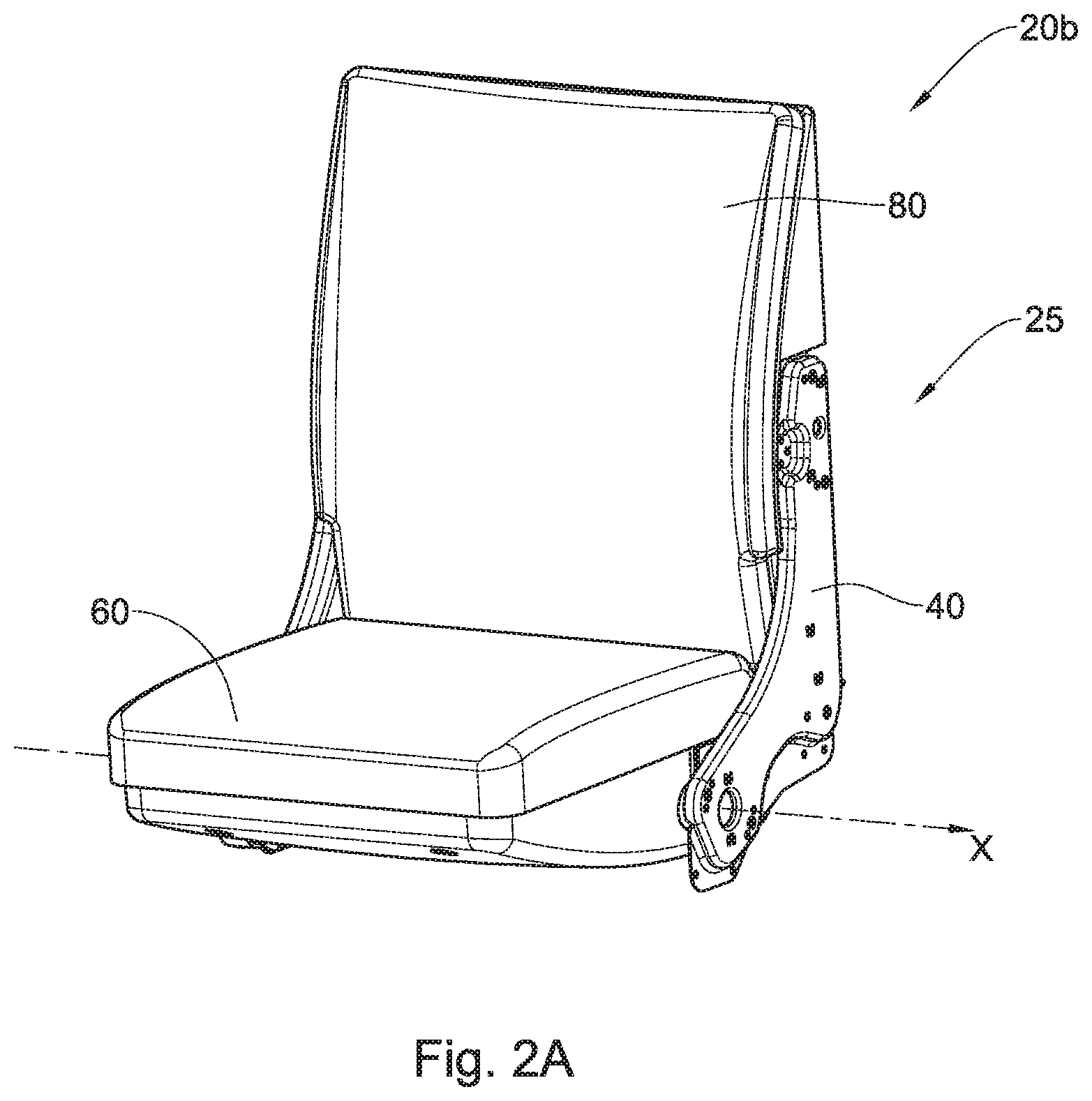
[0071] FIG. 2A is an isometric view of one seating unit of the modular seating system of FIG. 1A;
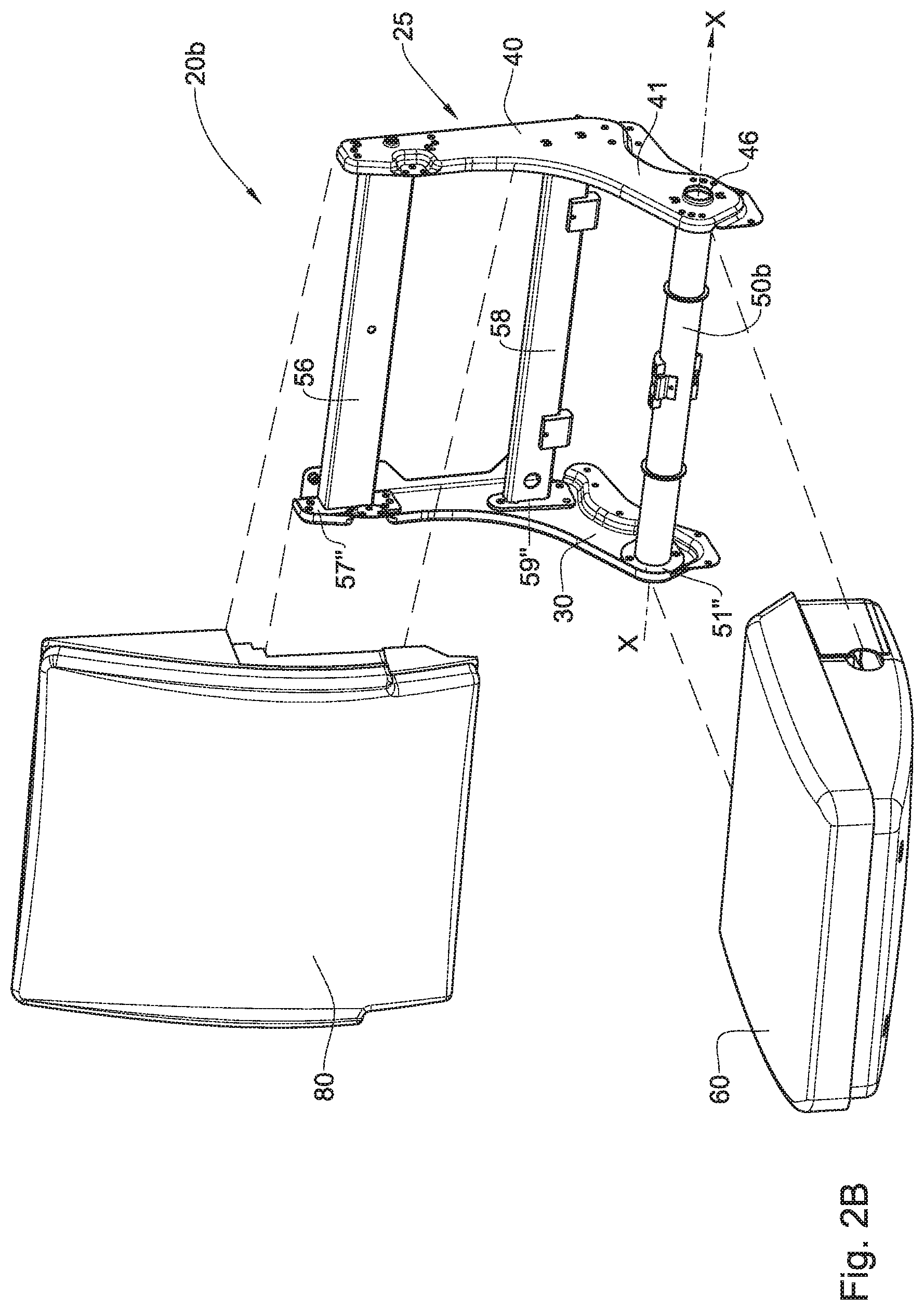
[0072] FIG. 2B is an exploded view of the seating unit of FIG. 2A;
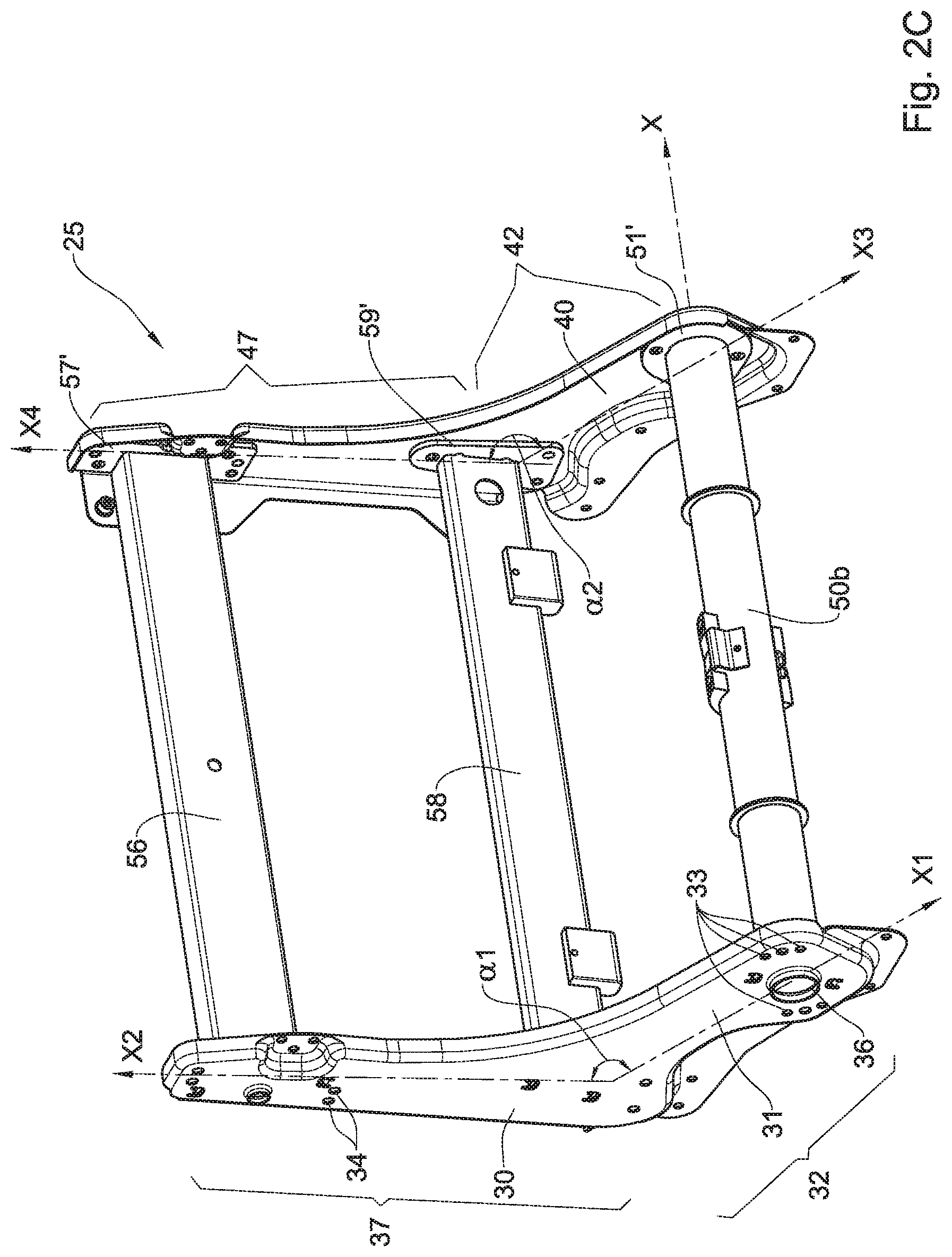
[0073] FIG. 2C is another isometric view of a frame structure of the seating unit of FIG. 2B;
[0074] FIG. 3A is a cross-sectional view along line A-A in FIG. 1A;
[0075] FIG. 3B is an enlarged view of section A1 of FIG. 3A;
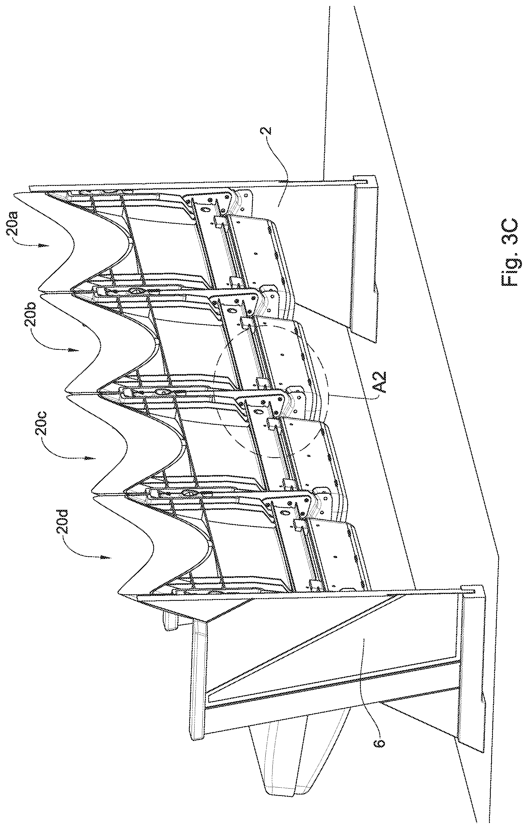
[0076] FIG. 3C is a cross-sectional view along line B-B in FIG. 1A;
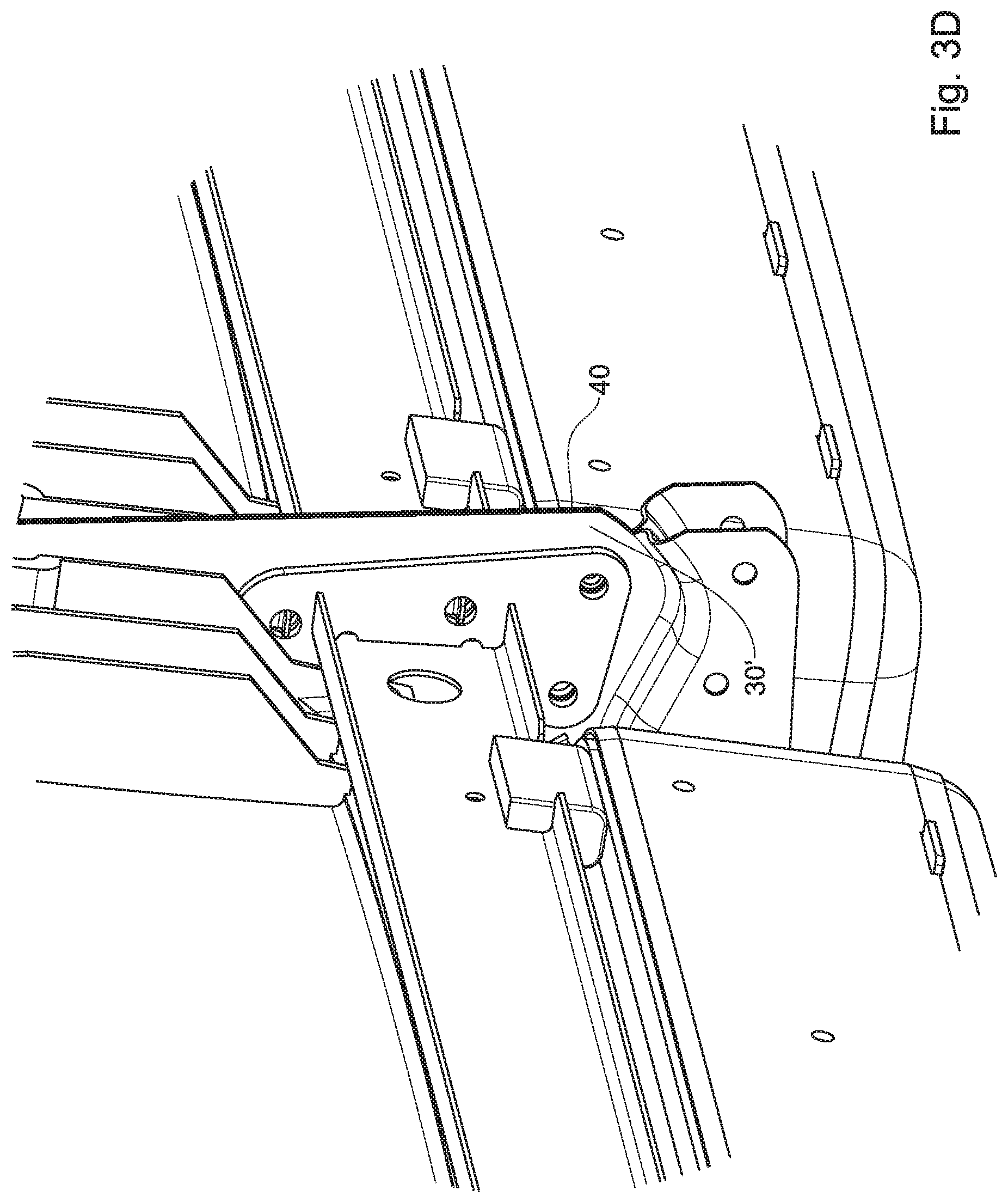
[0077] FIG. 3D is an enlarged view of section A2 of FIG. 3C;
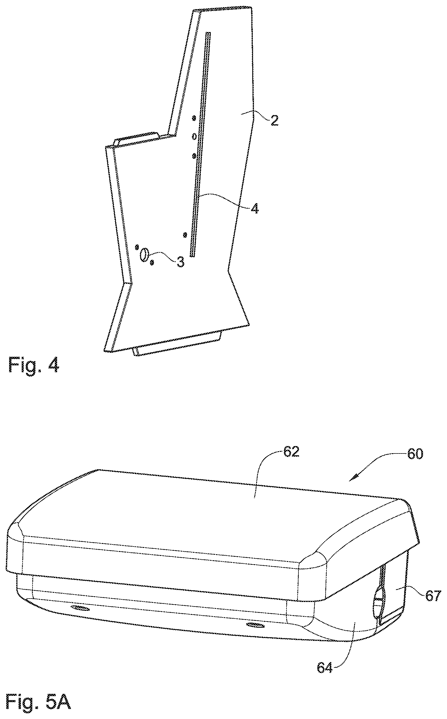
[0078] FIG. 4 is an isometric view of a right vertical leg of the modular seating system of FIG. 1A;
[0079] FIG. 5A is an enlarged view of a modular seat of the seating unit of FIG. 2B, in accordance with an example of the presently disclosed subject matter;
[0080] FIG. 5B is the seat of FIG. 5A in its disassembled form, shown from another point of view;
[0081] FIG. 5C is an exploded view of the seat of FIG. 5A;
[0082] FIG. 5D is a bottom isometric view of the seat of FIG. 5C;
[0083] FIG. 6A is a seating unit of the modular seating system of FIG. 1A with a hand rest attached thereto, shown without a back pad thereof;
[0084] FIG. 6B is a left isometric view of the seating unit of FIG. 6A; and
[0085] FIG. 6C is a right isometric view of the seating unit of FIG. 6B.
DETAILED DESCRIPTION OF EMBODIMENTS
[0086] Reference is now made to FIGS. 1A-B, 2A-C, 3A-D and 4 in which a modular seating system 1 is shown, in accordance with one example of the first, second and third aspects of the presently disclosed subject matter.
[0087] The modular seating system 1 is structured of four neighboring identical seating units 20a, 20b, 20c and 20d, attached to each other side-by-side in such a manner that their seat support members 50a, 50b, 50c and 50d are forming together a rigid longitudinal structure 20 extending along a longitudinal support axis X (shown in FIGS. 1 and 3A).
[0088] The modular seating system 1 further has two system support members in the form of a right vertical leg 2 and a left vertical leg 6. The right vertical leg 2 is connected to the seating unit 20a disposed at one end of the seating system 1 and the left vertical leg 6 is connected to the seating unit 20d, disposed at another end of the seating system 1. The right and left vertical legs 2 and 6 are disposed over a floor 100.
[0089] The rigid longitudinal structure 20 provides support for the seating system 1 and substantially prevents bending of the seating system 1 upon application of an external load L (shown in FIG. 1A) perpendicularly to the longitudinal support axis X (e.g., weight of one or more users sitting on one or more of the seating units 20a, 20b, 20c and 20d). The rigid longitudinal structure 20 provides stability to the seating system 1 when the external load L is applied thereon, without the necessity to connect or use one or more additional system support members (e.g., additional vertical legs) extending from intermediate seating units (i.e., the seating units 20b and 20c) to the floor 100.
[0090] Due to the structure of the seating units 20a-d and their connectivity to each other, which is explained in detail below, while providing the required stability and resistance to deformation of the seating system 1, the number of seating units of the seating system is flexible and can be determined in accordance with the available space or other requirements at the installation site of the seating system 1. For example, the number of the seating units can vary between two to six, seven and even more seating units in a single seating system, without using the additional system support members (i.e., in addition to the right and the left vertical legs). This flexibility is allowed, inter alia, due to the fact that each seating unit is provided with its own seat support member, which is modularly connectable to a seat support member of a neighboring seating unit forming together a continuous rigid longitudinal structure that provides support to the entire seating system.
[0091] Reference is now made specifically to FIGS. 2A-2C, in order to describe the structure of a single seating unit of the seating system 1. The description below is made with respect to the seating unit 20b, but is relevant similar to the seating units 20a, 20c and 20d.
[0092] The seating unit 20b comprises a frame structure 25, a seat 60 and a back 80. The seat 60 and the back 80 are mountable to the frame structure 25 as shown in FIG. 2B. The frame structure 25 is structured of the following components: a first lateral member 30 having a first mounting arrangement in the form of a protruding element 36 formed at an outer face 31 of the first lateral member 30; a second lateral member 40 opposing the first lateral member 30 and having a second mounting arrangement in the form of a recessed element 46 formed at an outer face 41 of the second lateral member 40; the seat support member 50b; an upper back support member 56; and a lower back support member 58. The seat support member 50b, the upper back support member 56 and the lower back support member 58 are extending between the first and the second lateral members 30 and 40 and connecting them to each other. The seat support member 50b, the protruding element 36 and the recessed element 46 coextend with each other along the longitudinal support axis X.
[0093] The seat support member 50b is bar-shaped and has a round cross-section, and the seat 60 is configured for pivotally displacing about the seat support member 50b between a normally deployed position (not shown) and an undeployed position (shown in FIG. 1A).
[0094] As shown in FIGS. 3A and 3B, the protruding element 36 is linked with a recessed element 46' of the seating unit 20a, which is identical to the recessed element 46, and the recessed element 46 is linked with a protruding element 36' of the seating unit 20c, which is identical to the protruding element 36. In addition, as shown in these figures, a protruding element 36' of the seating unit 20a is received in a respective recess 3 formed in the right vertical leg 2 to which the seating unit 20a is attached. Moreover, the left vertical leg 6 is provided with a protruding element 7 which is received within a recessed element 46'' of the seating unit 20d to which the left vertical leg 6 is attached.
[0095] According to an alternative example not shown in the drawings, both the first mounting arrangement and the second mounting arrangement can be either recessed elements or protruding elements, configured to be linked to a corresponding mounting arrangement of the neighboring seating unit by a connector element (e.g., a longitudinal linking member the ends of which are linked with the protruding/recessed elements of the neighboring seating units).
[0096] In order to improve the stability of the seating system when the external load L is applied thereon, each two neighboring first and second lateral members of the seating units 20a-d are screw-coupled to each other. The right and left vertical legs 2 and 6 are also screw-coupled to their neighboring first/second lateral members. For example, in order to couple the first lateral member 30 to its neighboring second lateral member of the seating unit 20a, the holes 33 and 34 (shown in FIG. 2C), and also other holes formed therein, can be used for screws which are accordingly received therein.
[0097] Moreover, as shown in FIG. 1B, the seating system 1 further comprises a back plate 15 to which the backs of the seating units 20a-d are screw-coupled. The back plate 15 provides further support to the entire seating system 1 for preventing the seating system 1 from bending upon application of the external load L. The back plate 15 also improves the stability of the seating system 1, and assists the rigid longitudinal structure 20 to withstand the external load L.
[0098] As shown in FIG. 4 in which the right vertical leg 2 is illustrated, the recess 3 can clearly be seen. In addition, the right vertical leg 2 has a longitudinal recess 4 into which a right end of the back plate 15 is to be received. The right vertical leg 2 also has a number of holes for screw-coupling the first lateral member of the seating unit 20a to the right vertical leg 2.
[0099] As shown in FIG. 2C, the first lateral member 30 is L-shaped and has a seat portion 32 with a seat axis X1 extending along its length, and a back portion 37 with a back axis X2 extending along its length and disposed at an angle .alpha.1 with respect to the seat main axis X1. The seat portion 32 and the back portion 37 are substantially flat and coplanar. The second lateral member 40 is also L-shaped and has a seat portion 42 with a seat axis X3 extending along its length, and a back portion 47 with a back axis X4 extending along its length and disposed at an angle .alpha.2 with respect to the seat main axis X3. The seat portion 42 and the back portion 47 are also substantially flat and coplanar. The angles .alpha.1 and .alpha.2 are equal.
[0100] The seat support member 50b is extending between the seat portions 32 and 42 and is configured with two opposing seat flange members 51' and 51'' disposed at ends thereof, attaching the seat support member 50b to the seat portions 32 and 42, respectively.
[0101] The upper back support member 56 is extending between the back portions 37 and 47 and is configured with two opposing back flange members 57' and 57'' disposed at ends thereof, attaching the upper back support member 56 to the back portions 37 and 47, respectively. The lower back support member 58 is extending between the back portions 37 and 47 and is configured with two opposing back flange members 59' and 59'' disposed at ends thereof, attaching the lower back support member 58 to the back portions 37 and 47, respectively.
[0102] The modular seating system 1 is further configured with cover members, such as cover members 17 and 18 (shown in FIG. 1A), each of which covers each pair of neighboring first and second lateral members. The cover members are esthetically sealing the lateral members by entirely covering their exterior upper portions when the seating units are connected to each other and the entire seating system is assembled.
[0103] FIGS. 3C and 3D illustrate the rear portions of the second lateral member 40 and its neighboring first lateral member 30' of the seating unit 20c. In these drawings it can clearly be seen that outer faces of the second lateral member 40 and the first lateral member 30' are tightly adjacent to each.
[0104] In summary, the modular seating system 1 is structured so as to optimally transfer the external load L applied on its seating units to the right and left vertical legs, while preserving the shape of the seating system and preventing it from bending. By this manner, the number of the seating units included in the system can be changed and determined in accordance with different requirements and spacial constraints at the installation site.
[0105] Reference is now made to FIGS. 5A-5D, in which a modular seat, in accordance with one example of the fourth and fifth aspects of the presently disclosed subject matter, is shown. Although the modular seat according to the present example is the seat 60 of FIGS. 1-4, it is appreciated that the modular seat of the fourth and fifth aspects is not necessarily tied to the examples of FIGS. 1-4, and can thus be used in conjunction with any other seating units known in the art. In FIG. 5A, the seat 60 is shown in its assembled form, and in FIG. 5B, the seat 60 is shown in its disassembled form.
[0106] The seat 60 comprises the following: a seat flat portion 61; a seat cushion 62 mounted on the seat flat portion 61; a first bearing member in the form of two bearings 63 having a rounded internal wall 63' and a first cover member 64 having a plurality of bearing portions 64'; and a second bearing member in the form of a second cover member 67 having two bearing portions 67'. The seat 60 further comprises a weight member 68 mounted to an internal wall 68' of the second cover member 67.
[0107] The rounded internal wall 63' of the bearings 63, the bearing portions 64' and the bearing portions 67' all have a rounded shape being complementary to the rounded shape of the seat support member 50c for accommodating respective portions of the seat support member 50c. The manner, in which the seat support member 50c is seated on the bearings 63 and on the bearing portions 64', is shown for example in FIG. 3B.
[0108] Each of the bearings 63 is seated on a profile 66 extending along the seat flat portion 61 and mounted thereto. The bearings 63, the first cover member 64 and the second cover member 67 are configured together for embracing the seat support member 50c (not shown in FIGS. 5A-D) therebetween. By this, the bearings 63, the first cover member 64 and the second cover member 67 are forming together a bearing assembly allowing pivotal displacement of the seat 60 about to the seat support member 50c between a deployed position and an undeployed position. In the deployed position (not shown in the drawings), the seat 60 is substantially parallel to the back 80. However, when displacing the seat 60 to the undeployed position (for example, in FIGS. 1A and 1B), a user can sit thereon.
[0109] The first cover member 64 has a receiving space 65 for accommodating the second cover member 67, when received therein in the assembled form of the seat 60, as shown in FIG. 5A.
[0110] The seat 60 is configured to be modularly installed on the seat support member 50b. This modularity is provided by two parts that are forming the seat 60. As shown in FIG. 5B, the seat flat portion 61, the seat cushion 62, the bearings 63 and the first cover member 64 constitute the first part of the seat 60, and the second cover member 67 together with the weight member 68 constitute the second part of the seat 60.
[0111] When the seat 60 is disassembled, the first and second parts are provided separately from each other. During assembly of the seat 60 on the seat support member 50b, the first cover member 64 and the bearings 63 are first seated on the seat support member 50b, and then, the second cover member 67 is attached to the first support member 63, thereby embracing the seat support member 50b.
[0112] In the assembled configuration of the seat 60, the weight member 68 is configured to cause the seat 60 to normally assume its deployed position. According to this configuration, the seat 60 is thus provided without any springs or any other compression or tension elements responsible for causing the seat 60 to automatically revert to its normally deployed position. It is known that such elements experience physical deterioration over time, and that if possible, it is preferable not to use them in a mechanical system. Therefore, the configuration of the seat 60 with the weight member 68 simplifies its structure and improves its reliability over time.
[0113] Reference is now made to FIGS. 6A-D in which a seating unit, in accordance with one example of the sixth and seventh aspects of the presently disclosed subject matter, is shown. Although the seating unit according to the present example is the seating unit 20c of FIGS. 1-4, it is appreciated that the seating unit of the sixth and seventh aspects is not necessarily tied to the examples of FIGS. 1-4, and can thus be used in conjunction with any other seating systems known in the art.
[0114] The seating unit 20c according to the present example allows selectively mounting a hand rest to the seating unit 20c, upon demand. For example, when there is a need to add a hand rest to the seating unit 20c, a respective side blocking element can be converted from its blocking state to its unblocking state, and a hand rest connector can be mounted to a respective hand rest receiving element. This hand rest can also be removed from the seating unit, and the respective side blocking element can afterwards be converted from its unblocking state to its blocking state. The structure of the seating unit 20c is detailed below.
[0115] The seating unit 20c comprises the first lateral member 30' and a second lateral member 40'. The first lateral member 30' is configured with a first hand rest receiving element 90 and the second lateral member 40' is configured with a second hand rest receiving element 92. A seat 50' and a back 80' are extending between the first and the second lateral members 30' and 40'.
[0116] The back 80' has a first side blocking element 94 disposed in front of the first hand rest receiving element 90. The blocking element 94 is selectively convertible between a blocking state (shown in FIG. 6C) in which it obstructs access of a hand rest connector (not shown) to the first hand rest receiving element 90, and an unblocking state in which said access is allowed for mounting the hand rest connector to the first hand rest receiving element. The blocking element 94 is connected to the back 80' by weakened areas 98 allowing for easy rotating and disconnecting of the blocking element 94 from the back 80' when converted to its unblocking state.
[0117] The back 80' also had a second side blocking element which was disposed in front of the second hand rest receiving element 92. However, the second side blocking element was already disconnected from the back 80' when being converted to its unblocking state, in order to allow access to the second hand rest receiving element 92 for mounting a hand rest connector 110 of a hand rest 105 to the second hand rest receiving element 92.
* * * * *
D00000
D00001
D00002
D00003
D00004
D00005
D00006
D00007
D00008
D00009
D00010
D00011
D00012

D00013

D00014

XML
uspto.report is an independent third-party trademark research tool that is not affiliated, endorsed, or sponsored by the United States Patent and Trademark Office (USPTO) or any other governmental organization. The information provided by uspto.report is based on publicly available data at the time of writing and is intended for informational purposes only.
While we strive to provide accurate and up-to-date information, we do not guarantee the accuracy, completeness, reliability, or suitability of the information displayed on this site. The use of this site is at your own risk. Any reliance you place on such information is therefore strictly at your own risk.
All official trademark data, including owner information, should be verified by visiting the official USPTO website at www.uspto.gov. This site is not intended to replace professional legal advice and should not be used as a substitute for consulting with a legal professional who is knowledgeable about trademark law.