Layers With Cells In Footwear
LOPEZ; Matthew G. ; et al.
U.S. patent application number 16/083110 was filed with the patent office on 2020-09-24 for layers with cells in footwear. This patent application is currently assigned to HEWLETT-PACKARD DEVELOPMENT COMPANY, L.P.. The applicant listed for this patent is HEWLETT-PACKARD DEVELOPMENT COMPANY, L.P.. Invention is credited to Roya Susan AKHAVAIN, Matthew G. LOPEZ, Edward PONOMAREV.
| Application Number | 20200297068 16/083110 |
| Document ID | / |
| Family ID | 1000004903713 |
| Filed Date | 2020-09-24 |


| United States Patent Application | 20200297068 |
| Kind Code | A1 |
| LOPEZ; Matthew G. ; et al. | September 24, 2020 |
LAYERS WITH CELLS IN FOOTWEAR
Abstract
In some examples, a sole layer for a footwear includes a housing structure, a cell in the housing structure, a solid support inside the cell to maintain a shape of the cell, and an inlet to the cell to receive an injected material to dissolve the solid support.
| Inventors: | LOPEZ; Matthew G.; (San Diego, CA) ; AKHAVAIN; Roya Susan; (San Diego, CA) ; PONOMAREV; Edward; (San Diego, CA) | ||||||||||
| Applicant: |
|
||||||||||
|---|---|---|---|---|---|---|---|---|---|---|---|
| Assignee: | HEWLETT-PACKARD DEVELOPMENT
COMPANY, L.P. Houston TX |
||||||||||
| Family ID: | 1000004903713 | ||||||||||
| Appl. No.: | 16/083110 | ||||||||||
| Filed: | April 10, 2017 | ||||||||||
| PCT Filed: | April 10, 2017 | ||||||||||
| PCT NO: | PCT/US2017/026779 | ||||||||||
| 371 Date: | September 7, 2018 |
| Current U.S. Class: | 1/1 |
| Current CPC Class: | A43B 7/28 20130101; A43B 7/144 20130101; A43B 13/188 20130101; A43B 7/142 20130101; B32B 2250/03 20130101; B32B 2437/02 20130101; A43B 7/1465 20130101; A43B 13/20 20130101 |
| International Class: | A43B 7/28 20060101 A43B007/28; A43B 7/14 20060101 A43B007/14 |
Claims
1. A sole layer for a footwear, comprising: a housing structure; a cell in the housing structure; a solid support inside the cell to maintain a shape of the cell; and an inlet to the cell to receive an injected material to dissolve the solid support.
2. The sole layer of claim 1, wherein the solid support has a lattice shape.
3. The sole layer of claim 1, wherein the cell is a first cell, the solid support is a first solid support, and the inlet is a first inlet, the sole layer further comprising: a second cell in the housing structure; a second solid support inside the second cell to maintain a shape of the second cell; and a second inlet to the second cell to receive an injected material to dissolve the second solid support.
4. The sole layer of claim 3, wherein the first and second cells are to receive respective materials through the first and second inlets after dissolution of the first and second solid supports.
5. The sole layer of claim 1, wherein the sole layer is to be attached as part of a plurality of layers in a sole of the footwear during manufacture of the footwear.
6. An assembly comprising: a footwear comprising a sole including a plurality of layers, a first layer of the plurality of layers comprising: a plurality of cells; solid supports inside respective cells of the plurality of cells; and inlets to the respective cells to receive injected materials to dissolve the solid supports.
7. The assembly of claim 6, wherein upon dissolution of the solid supports, the inlets are to receive additional materials to fill the respective cells.
8. The assembly of claim 7, wherein the further materials are selected from among a fluid, a foam, a plastic, and wax.
9. The assembly of claim 7, wherein the further materials in at least two of the respective cells are of different types.
10. The assembly of claim 6, wherein the inlets comprise self-sealing membranes.
11. The assembly of claim 6, wherein the injected materials to dissolve the solid supports comprise liquid.
12. The assembly of claim 6, further comprising an injection kit comprising an injection element to inject a first material into a first cell of the plurality of cells after the solid support in the first cell has been dissolved.
13. The assembly of claim 12, wherein the injection kit further comprises a second injection element to inject a second material into a second cell of the plurality of cells after the solid support in the second cell has been dissolved, wherein the first material is different from the second material.
14. A method of forming a sole for a footwear, comprising: providing a sole layer of the sole, the sole layer comprising a cell including an inner cavity to receive a material injected through an inlet, to customize support for a foot of a user; and arranging a solid support in the inner cavity of the cell, the solid support to break up inside the inner cavity of the cell in response to an applied force.
15. The method of claim 14, wherein the solid support before breaking up is to provide support to prevent collapse of the cell.
Description
BACKGROUND
[0001] Various footwear can be worn on the feet of users. Footwear can be used for various purposes, including walking, jogging, playing sports, and so forth. Users desire that footwear be comfortable and provide adequate support when the users are engaged in various activities.
BRIEF DESCRIPTION OF THE DRAWINGS
[0002] Some implementations of the present disclosure are described with respect to the following figures.
[0003] FIG. 1 is a perspective view of a portion of a footwear according to some examples.
[0004] FIG. 2 is a schematic view of a solid support having a lattice shape, according to further examples.
[0005] FIG. 3 is a bottom view of a sole layer of a footwear, according to some examples.
[0006] FIG. 4 is a perspective bottom view of a sole layer of a footwear, according to some examples.
[0007] FIG. 5 is a perspective exploded view of various layers of a sole of a footwear, according to some examples.
[0008] FIG. 6 is a perspective assembled view of various layers of a sole of a footwear, according to some examples.
[0009] FIG. 7 is a bottom perspective view of an assembly including various layers of a sole, along with an injection element to inject a material into a cell of a sole layer, according to some examples.
[0010] FIG. 8 is a flow diagram of a footwear customizing process according to some examples.
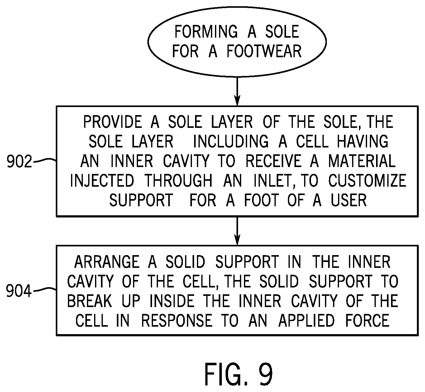
[0011] FIG. 9 is a flow diagram of forming a sole of a footwear, according to further examples.
[0012] Throughout the drawings, identical reference numbers designate similar, but not necessarily identical, elements. The figures are not necessarily to scale, and the size of some parts may be exaggerated to more clearly illustrate the example shown. Moreover, the drawings provide examples and/or implementations consistent with the description; however, the description is not limited to the examples and/or implementations provided in the drawings.
DETAILED DESCRIPTION
[0013] In the present disclosure, use of the term "a," "an", or "the" is intended to include the plural forms as well, unless the context clearly indicates otherwise. Also, the term "includes," "including," "comprises," "comprising," "have," or "having" when used in this disclosure specifies the presence of the stated elements, but do not preclude the presence or addition of other elements.
[0014] Examples of footwear include shoes, sandals, boots, socks, or any other article that is to be worn on a foot (or feet) of a user. The sole of a footwear is designed to support a foot of a user. The sole can refer generally to a footwear's underlying structure on which the user's foot is placed and which provides support for the user's foot. Feet of different users can have different shapes and other characteristics. Thus, footwear that may satisfactorily support the feet of one user may not adequately support the feet of another user. Moreover, footwear can be used in different activities, including walking, jogging, playing sports, standing, and so forth, which can be associated with different support and user comfort issues. Inadequate support for a user's feet can result in discomfort or pain to the user, and in some cases can lead to damage to the user's feet.
[0015] After a user purchases a footwear and finds that it does not provide adequate support or comfort (either because the footwear does not conform properly to the shape of the user's feet or the footwear does not provide adequate support for the user's intended activity), the user may either return the footwear to the retailer (which results in added cost to the retailer), or the user may purchase additional inserts to place in the footwear to add support or improve comfort (which results in added cost to the user).
[0016] In accordance with some implementations of the present disclosure, solutions are provided to allow footwear to be individually customized for respective users. In some examples, a footwear can include cells that can be customized on demand. As used here, a "cell" can refer to a containing structure, such as a pouch, pocket, or any other receptacle in which is provided an inner cavity. The cells are provided as part of a layer of a sole of a footwear.
[0017] The sole can be formed of multiple layers (referred to as "sole layers"), where one sole layer of the multiple sole layers can include cells according to some implementations of the present disclosure. In other examples, more than one sole layer can include cells according to some implementations.
[0018] Cells in a sole layer can be injected with respective materials to customize a footwear for a user. Different cells in a sole layer can be injected with a same type of material, or with different types of materials. Different types of materials can be injected into the cells of the sole layer to achieve different dynamic behaviors of the sole layer, such as different dynamic performance of the elastomer material (or other material) that is used to form the sole (or a portion of the sole). The selection of a material to inject into each cell of a sole layer can depend on any one or some combination of the following factors: the shape of a user's foot, the size of the user's foot, the characteristic of an arch of the user's foot (e.g., high arch or low arch), the target use of the footwear (e.g., walking, jogging, running, basketball, soccer, football, standing, etc.), or other factors.
[0019] By selecting different types of materials or different amounts of materials to inject into cells, footwear can be individually customized for a user. In some examples, the customizing can be performed in a retail setting (such as in a footwear store) or in the home or other facility of a user who has purchased the footwear. In other examples, the customizing can be performed by a manufacturer at the manufacturer's factory. In further examples, the customizing can be performed in another setting or by another entity.
[0020] Although reference is made to a sole layer having multiple cells in some examples, it is noted that in other examples, a sole layer can include just a single cell into which a material can be injected for customization.
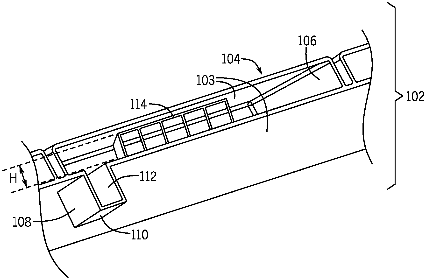
[0021] FIG. 1 is perspective view of a portion of a sole layer 102 that is part of a footwear, according to some examples. The sole layer has a housing structure 103 which is the main outer structure of the sole layer 102.
[0022] The sole layer 102 includes a cell 104, which has an inner cavity 106. An inlet 108 is provided to allow for injection of a material into the inner cavity 106 of the cell 104.
[0023] The inlet 108 includes a membrane 110 through which an injection element can pass and extend into an inner channel 112 of the inlet 108. For example, the injection element can include the needle of a syringe, which can penetrate through the membrane 110 to allow for a material in the syringe to be injected into the inner cavity 106 of the cell 104. When the syringe needle is removed from the inlet 108, the membrane 110 is self-sealing such that any material that is in the inner cavity 106 of the cell 104 remains in the cell 104 after the syringe needle has been removed.
[0024] In other examples, instead of using the self-sealing membrane 110, a different capping layer can be provided to cap an opening of the inlet 108 after a material has been injected into the cell 104. For example, the capping layer can include a lid that is removable from the inlet 108 to allow a material to be delivered through the inlet 108 into the inner cavity 106. After delivering the material into the cell 104, the lid can be re-attached to the inlet. In other examples, other types of capping layers can be used.
[0025] In accordance with some implementations of the present disclosure, to ensure that the cells in a footwear maintain their shape during shipment and/or other handling of the footwear, a solid support can be provided in each cell. FIG. 1 shows a solid support 114 that is initially provided in the inner cavity 106 of the cell 104. The solid support 114 is to provide initial support of the cell 104 after manufacture of the footwear (or the sole layer 102), such that the cell 104 can maintain its expanded shape as shown in FIG. 1. Without the solid support 114, the cell 104 may be collapsed when force is applied onto the cell 104, such as during handling, shipment, or storage, which can make injecting a material into the cell 104 more difficult.
[0026] As shown in FIG. 1, the solid support 114 has a height that is approximately the height (to within .+-.5%, or .+-.10%, or .+-.20% of the height of the inner cavity 106 of the cell 104.
[0027] In some examples, the solid support 114 is formed of a dissolvable material, which can be dissolved when a fluid is injected into the inner cavity 106 of the cell 104 through the inlet 108. Dissolving a solid can refer to a conversion process in which the solid is converted into solutes (dissolved components), to form a solution of the fluid and the solutes. In some examples, the solid support 114 can be formed of a material that includes polyvinyl alcohol (PVA), which is a water-soluble synthetic polymer. The PVA solid support 114 remains as a solid in the absence of a solvent. However, once the solvent is introduced into the inner cavity 106 of the cell 104, the PVA solid support 114 dissolves. In some examples, the solvent can include water. In other examples, the solvent can include a warm, high-alkaline water based liquid plus a thickening agent, such as polyethylene glycol.
[0028] The amount of solvent that is injected into the inner cavity 106 of the cell 104 to dissolve the PVA solid support 114 can be a relatively small amount that does not fill the entirety of the inner cavity 106 of the cell 104. Thus, once the solid support 114 dissolves in the presence of the solvent, the inner cavity 106 of the cell 104 is just partially filled, to allow more material to be injected into the inner cavity 106 of the cell 104 if desired.
[0029] Other example materials of a solid support 114 can include non-hydrated silica gel crystals, sodium chloride or any other solid material that can be dissolved in the presence of a solvent, such as water or other fluid, or any other type of solvent.
[0030] More generally, a chemical characteristic of the solid support 114 can be used to determine what solvent would be effective in dissolving the solid support 114. For example, the chemical characteristic can be the pH of the solid support 114, where the pH determines what solvent would be effective to dissolve the solid support 114.
[0031] After dissolution of the solid support 114, a selected material can be injected into the inner cavity 106 of the cell 104. The injected material can include a fluid, such as a liquid or a gas. In other examples, the material injected into the cell 104 can include a foam, a solid (e.g., a wax, a plastic, etc.), or another material.
[0032] In some examples, different types of materials can include a Newtonian fluid and a non-Newtonian fluid. The viscosity of a Newtonian fluid is independent of the rate of shear of the fluid. Examples Newtonian fluids include water or air. In contrast, the viscosity of a non-Newtonian fluid is dependent on the rate of shear. Most fluids are non-Newtonian fluids. One type of non-Newtonian fluid is a dilatant fluid (or shear thickening fluid), which has a viscosity that increases with the shear strain. Another type of non-Newtonian fluid is a pseudoplatic fluid (or shear thinning fluid), which has a viscosity that decreases with shear strain.
[0033] In other implementations, instead of dissolving the solid support 114 using a solvent, a mechanical force can be applied to the solid support 114 to break up the solid support 114 into smaller pieces. For example, after a selected material is injected into the inner cavity 106 of the cell 104 to customize support for a user's foot, a mechanical force is applied to break up the solid support 114. The mechanical force can be applied by bending the sole of the footwear that includes the sole layer 102.
[0034] FIG. 2 is an upper view of the solid support 114 according to some examples. In FIG. 2, the solid support 114 has a lattice shape, which includes strips of materials arranged in rows and columns. In other examples, the solid support 114 can have a different shape or arrangement, so long as the solid support 114 is able to provide structural support to maintain the general shape of the cell 104.
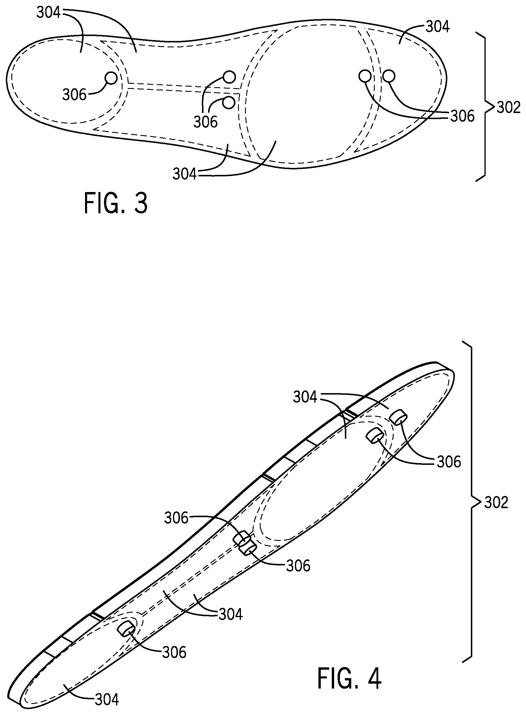
[0035] FIG. 3 is a bottom view of a sole layer 302 that has multiple cells 304. FIG. 4 is a perspective bottom view of the sole layer 302. In the example of FIGS. 3 and 4, five cells are shown as part of the sole layer 302. In different examples, a different number of cells can be part of the sole layer 302. Each cell 304 has a respective inlet 306 that allows for a material to be injected into the respective cell 304. Each cell 304 and inlet 306 can have an arrangement similar to the cell 104 and inlet 108, respectively, shown in FIG. 1.
[0036] In some examples, the housing structure of the sole layer 302 can be formed of two polyethylene films, which can be sealed together to form the cells 304. In some examples, the films can be sealed using an ultrasonic sealing process. Ultrasonic sealing involves applying ultrasonic vibration to the polyethylene films to seal the films together. In other examples, other types of films or layers can be employed to form the sole layer 302.
[0037] In some examples, the cells 304 are formed using a vacuum process during the ultrasonic sealing. The vacuum process can be used to evacuate chambers inside the sole layer 302.
[0038] The multiple cells 304 shown in FIGS. 3 and 4 can correspond to different parts of a user's foot, including the heel, arch, outer arch, metatarsal, and toe box, as examples.
[0039] When customizing a footwear including the sole layer 302 for an individual user, selected materials can be injected into the cells 304. In some examples, the same type of material can be injected into each of the cells 304. In other examples, a first type of material can be injected into a first of the cells 304, while a different second type of material can be injected into a second of the cells 304.
[0040] In further examples, materials do not have to be injected into all of the cells 304. A subset of the cells 304 can be left un-injected with any material, leaving the solid support 114 in each such cell 304.
[0041] The customization of a footwear including the sole layer 302 for an individual user can occur in any of various different settings. In a retail store setting, a pressure mat or other type of measuring mechanism can be used to measure the profile of each region of the user's feet. The pressure mat can measure the pressures applied by different portions of each foot. Based on measured pressures, a determination can be made regarding the support that is to be provided by different portions of the footwear, which can lead to the decision of what material to inject into each cell 304 (or whether to not inject any material into a particular cell 304).
[0042] In other examples, an imaging system can be used to capture a three-dimensional (3D) image of the user's feet, and based on the 3D image, a decision can be made regarding materials to inject (or not) into respective cells 304.
[0043] The decision regarding which cells should be injected with materials, and which materials to use for each cell, can be made by a human, or by a computer, based on empirical data collected from tests conducted on users with feet of varying shapes and who use footwear for different purposes.
[0044] In other examples, the customization of a footwear using the cells of the sole layer 302 (or the cell 104 of the sole layer 102) can occur at the factory of a manufacturer of the footwear, or in the home of a user who purchased the footwear. In examples where the user is to perform the customization, materials for injection into the cells of the sole layer 302 can be shipped to the user with the footwear, along with instructions on how to inject the materials. For example, an injection kit can be provided with the footwear, where the injection kit can include a syringe, or multiple syringes (or other types of injection elements), which can be used to inject the materials into respective cells 304 of the sole layer 302.
[0045] If a user expresses dissatisfaction with the support provided by a particular cell (or cells) that has (have) been injected with materials, a retailer or manufacturer can send replacement materials (possibly with another injection kit) to the user, to replace the material(s) previously injected into the cell(s).
[0046] Replacing a material in a cell 304 can involve withdrawing the material from the cell 304, and replacing the material with a different material. For example, a syringe can be used to withdraw a material from a cell, and a different syringe can be used to inject a new material into the cell.
[0047] In accordance with some examples, the sole layer 302 can be manufactured to be part of other layers of the sole of a footwear. In such examples, the sole layer 302 is attached to other layers of a sole of the footwear. For example, FIG. 5 shows an exploded view of the layers of a sole 500 of a footwear, such as a shoe or other type of footwear. The layers of the sole 500 include an outer sole layer 502, a midsole layer 504, and the sole layer 302 with cells 304.
[0048] The sole layer 302 with cells 304 can be received in a receptacle 506 of the midsole layer 504. The sole layer 302 can thus reside within the side wall 510 of the midsole layer 504. In some examples, the sole layer 302 with cells 304 can reside entirely within the receptacle 506 defined by the side wall 510 of the midsole layer 504.
[0049] The sole layer 302 with cells 304 can be affixed to a surface 508 (e.g., the upper surface) of the midsole layer 504. The affixing of the sole layer 302 to the surface 508 of the midsole layer 504 can be performed by using an adhesive or other type of fastener. The midsole layer 504 is in turn affixed to the outer sole layer 502, either by an adhesive or a different fastener. Although just a few sole layers are shown as being part of the sole 500 of FIG. 5, it is noted that in other examples, a different number of sole layers can be provided as part of the sole 500.
[0050] The outer sole layer 502 has openings 512 that align with the inlets 306 (FIG. 3) of the sole layer 302. As further shown in FIG. 5, corresponding openings 514 are formed in the midsole layer 504, which are aligned with the openings 512 in the outer sole layer 502 as well as with the openings 512 in the outer sole layer 502. The aligned openings 512 and 514 allow injection elements to pass through the respective openings 512, 514, to inject respective materials through the inlets 306 of respective cells 304 of the sole layer 302.
[0051] In some examples, the sole layer 302 is placed on the midsole layer 504 prior to installation of the upper of the footwear, where the upper refers to the upper structure of the footwear that covers the upper part of the foot of the user. The upper can be formed of a fabric, leather, or any other type of material.
[0052] FIG. 6 is an assembled view that shows the sole 500 with the outer sole layer 502, midsole layer 504, and sole layer 302 with cells all attached together in an assembly.
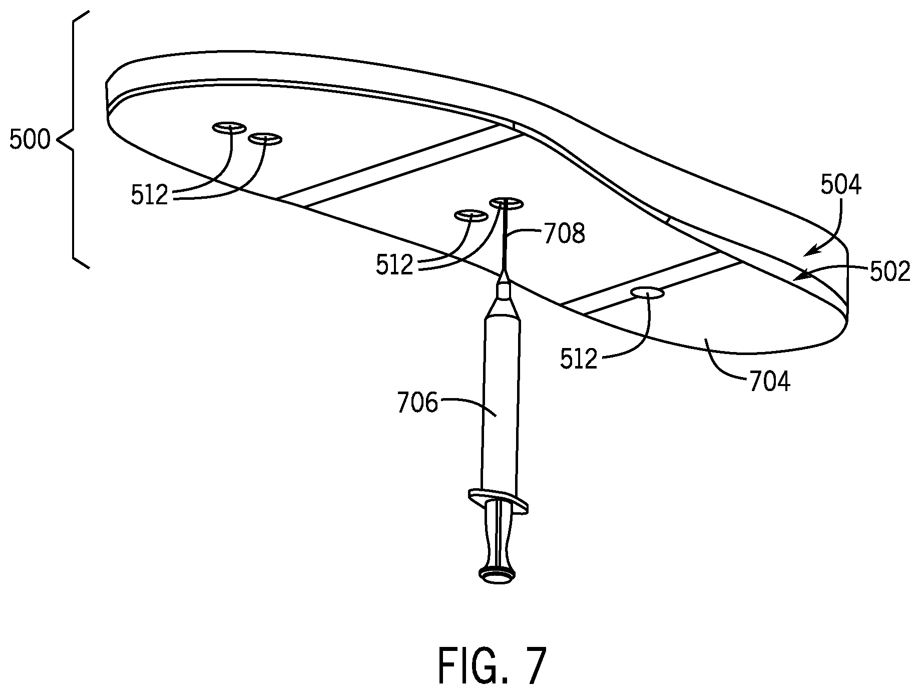
[0053] FIG. 7 is a bottom perspective view of the sole 500 of FIG. 6, which shows openings 702 formed in the bottom surface 704 of the outer sole layer 502. In the example of FIG. 7, an injection element 706 is used to inject a material into a cell of the sole layer 302 through a respective opening 512. In the example of FIG. 7, the injection element 706 is a syringe that has a needle 708 that can penetrate through the membrane of a respective inlet (such as 306 shown in FIG. 3).
[0054] Although FIG. 7 shows just one injection element 706, it is noted that in other examples, multiple injection elements can be used to deliver respective materials to corresponding cells 304 of the sole layer 302.
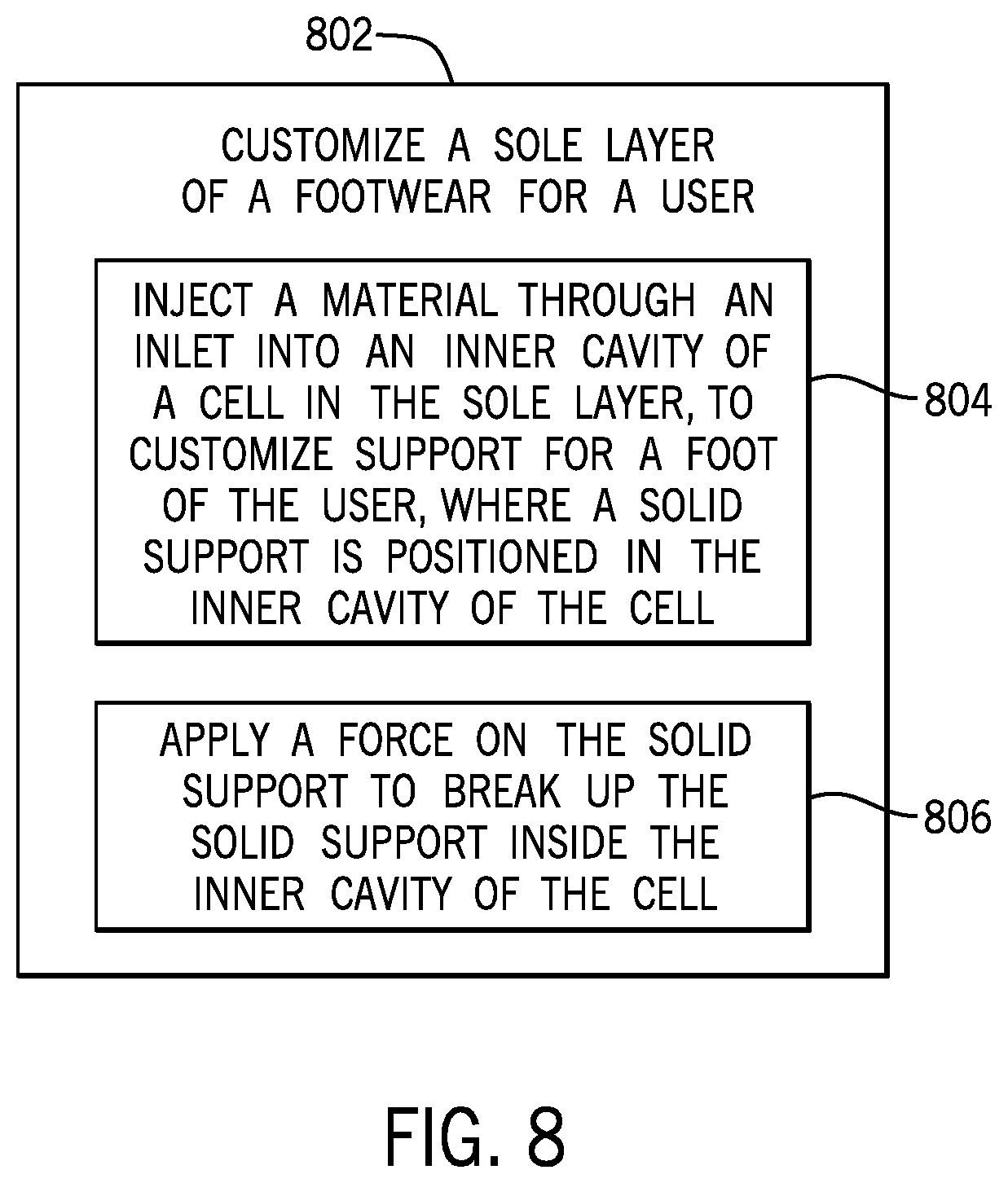
[0055] FIG. 8 is a flow diagram of a process that includes customizing (at 802) a sole layer of a footwear for a user. Customizing includes injecting (at 804) a material through an inlet into an inner cavity of a cell in the sole layer, to customize support for a foot of a user, where a solid support is positioned in the inner cavity of the cell. The customizing further includes applying (at 806) a force on the solid support to break up the solid support inside the inner cavity of the cell.
[0056] FIG. 9 is a flow diagram of a process of forming a sole for a footwear. The process of FIG. 9 includes providing (at 902) a sole layer of the sole, the sole layer including a cell having an inner cavity to receive a material injected through an inlet, to customize support for a foot of a user. The process of FIG. 9 further includes arranging (at 904) a solid support in the inner cavity of the cell, the solid support to break up inside the inner cavity of the cell in response to an applied force.
[0057] In the foregoing description, numerous details are set forth to provide an understanding of the subject disclosed herein. However, implementations may be practiced without some of these details. Other implementations may include modifications and variations from the details discussed above. It is intended that the appended claims cover such modifications and variations.
* * * * *
D00000
D00001
D00002
D00003
D00004
D00005
D00006
XML
uspto.report is an independent third-party trademark research tool that is not affiliated, endorsed, or sponsored by the United States Patent and Trademark Office (USPTO) or any other governmental organization. The information provided by uspto.report is based on publicly available data at the time of writing and is intended for informational purposes only.
While we strive to provide accurate and up-to-date information, we do not guarantee the accuracy, completeness, reliability, or suitability of the information displayed on this site. The use of this site is at your own risk. Any reliance you place on such information is therefore strictly at your own risk.
All official trademark data, including owner information, should be verified by visiting the official USPTO website at www.uspto.gov. This site is not intended to replace professional legal advice and should not be used as a substitute for consulting with a legal professional who is knowledgeable about trademark law.