Sensor Assemblies and Methods for Emulating Interaction of Entities Within Water Systems
Deng; Z. Daniel ; et al.
U.S. patent application number 16/351373 was filed with the patent office on 2020-09-17 for sensor assemblies and methods for emulating interaction of entities within water systems. This patent application is currently assigned to Battelle Memorial Institute. The applicant listed for this patent is Battelle Memorial Institute. Invention is credited to Z. Daniel Deng, Hongfei Hou, Jun Lu, Jayson J. Martinez, Mitchell J. Myjak, Aljon L. Salalila.
| Application Number | 20200296854 16/351373 |
| Document ID | / |
| Family ID | 1000004096702 |
| Filed Date | 2020-09-17 |


| United States Patent Application | 20200296854 |
| Kind Code | A1 |
| Deng; Z. Daniel ; et al. | September 17, 2020 |
Sensor Assemblies and Methods for Emulating Interaction of Entities Within Water Systems
Abstract
Sensor assemblies are provided for use in modeling water systems. These sensor assemblies can be used as sensor fish. These assemblies can include a circuit board supporting processing circuitry components on either or both opposing component support surfaces of the circuit board and a housing above the circuit board and the components, with the housing being circular about the circuit board in at least one cross section, and wherein the supporting surfaces of the circuit board are substantially parallel with the plane of the housing in the one cross section. Methods for emulating interaction of entities within water systems are provided. The methods can include introducing a sensor assembly into a water system. The sensor assembly can include: a circuit board supporting processing circuitry components on either or both of opposing component support surfaces of the circuit board; a housing about the circuit board and the components, the housing being circular about the circuit board in at least one cross section; and wherein the support surfaces of the circuit board are substantially parallel with the plane of the housing in the one cross section.
| Inventors: | Deng; Z. Daniel; (Richland, WA) ; Lu; Jun; (Richland, WA) ; Martinez; Jayson J.; (Richland, WA) ; Salalila; Aljon L.; (Richland, WA) ; Myjak; Mitchell J.; (Richland, WA) ; Hou; Hongfei; (Richland, WA) | ||||||||||
| Applicant: |
|
||||||||||
|---|---|---|---|---|---|---|---|---|---|---|---|
| Assignee: | Battelle Memorial Institute |
||||||||||
| Family ID: | 1000004096702 | ||||||||||
| Appl. No.: | 16/351373 | ||||||||||
| Filed: | March 12, 2019 |
| Current U.S. Class: | 1/1 |
| Current CPC Class: | G01L 19/148 20130101; H05K 7/1427 20130101; G01R 33/0047 20130101 |
| International Class: | H05K 7/14 20060101 H05K007/14; G01R 33/00 20060101 G01R033/00; G01L 19/14 20060101 G01L019/14 |
Goverment Interests
STATEMENT AS TO RIGHTS TO INVENTIONS MADE UNDER FEDERALLY-SPONSORED RESEARCH AND DEVELOPMENT
[0002] This invention was made with Government support under Contract DE-AC0576RL01830 awarded by the U.S. Department of Energy. The Government has certain rights in the invention.
Claims
1. A sensor assembly for use in modeling water systems, the assembly comprising: a circuit board supporting processing circuitry components on either or both of opposing component support surfaces of the circuit board; a housing about the circuit board and the components, the housing being circular about the circuit board in at least one cross section; and wherein the support surfaces of the circuit board define a perimeter plane substantially parallel with the plane of the housing in the one cross section.
2. The assembly of claim 1 wherein at least a portion of the housing defines a tube.
3. The assembly of claim 2 wherein the housing defines opposing ends of the tube.
4. The assembly of claim 3 wherein at least one of the opposing ends of the tube is configured to facilitate coupling to another object.
5. The assembly of claim 1 wherein the housing defines a sphere.
6. The assembly of claim 5 wherein the sphere defines opposing ends.
7. The assembly of claim 6 wherein at least one of the opposing ends of the sphere is configured to facilitate coupling to another object.
8. The assembly of claim 1 wherein the housing defines an internal volume of less than 3.76 cm3.
9. The assembly of claim 1 wherein the housing defines opposing ends having distance there between of less than 23 mm in at least one cross section.
10. The assembly of claim 1 further comprising a single component magnetometer.
11. The assembly of claim 1 further comprising pressure sensor amplifier circuitry.
12. The assembly of claim 11 wherein the pressure sensor amplifier circuitry is a single component.
13. The assembly of claim 11 wherein the pressure sensor amplifier circuitry is less than 3 mm.times.3 mm in area in all cross sections.
14. The assembly of claim 1 further comprising a magnetic sensor component.
15. The assembly of claim 14 wherein the magnetic sensor component is less than 1.1 mm.times.1.4 mm in area in at least one cross section.
16. The assembly of claim 1 further comprising a base configured to attach to hydroelectric turbine blades.
17. A method for emulating interaction of entities within water systems, the method comprising introducing a sensor assembly into a water system, the sensor assembly comprising: a circuit board supporting processing circuitry components on either or both of opposing component support surfaces of the circuit board; a housing about the circuit board and the components, the housing being circular about the circuit board in at least one cross section; and wherein the support surfaces of the circuit board are substantially parallel with the plane of the housing in the one cross section.
18. The method of claim 17 wherein the sensor assembly amplifies pressure sensing input from a single component.
19. The method of claim 17 wherein the sensor assembly determines magnetic field from a single component.
20. The method of claim 17 wherein the sensor assembly charges a battery and regulates voltages from a single component.
21. The method of claim 17 wherein the sensor assembly is less than 6.4 grams.
22. The method of claim 17 wherein the water system includes hydropower dam.
23. The method of claim 17 further comprising coupling the sensor assembly to a turbine blade of the hydroelectric generator to determine machine dynamics.
Description
CROSS REFERENCE TO RELATED APPLICATIONS
[0001] This application is related to U.S. patent application Ser. No. 14/871,761 filed Sep. 30, 2015, entitled "Autonomous Sensor Fish to Support Advanced Hydropower Development", now U.S. Pat. No. 10,067,112 issued Sep. 4, 2018, the entirety of which is incorporated by reference herein.
TECHNICAL FIELD
[0003] The present disclosure relates to sensor assemblies and methods for emulating interaction of entities within water systems. Water systems in relation to hydropower facilities is just one method of emulation.
BACKGROUND
[0004] Animals interact within water systems differently depending on the animal and the system. Modeling interactions of animal within water systems is important for many reasons, but recently, and significantly, it is important to determine the impact of water barriers such as dams, including hydropower dams, on animals such as fish. However, other systems, such as aqueducts, refurbished drainage, and/or aqueduct systems may be modeled as well.
[0005] In one particular example, it is important for many reasons to track or forecast fish passing through hydro-turbines or other hydraulic structures. Fish may be injured or killed when they are exposed to the severe hydraulic conditions found therein. Such conditions could include rapid and extreme pressure changes, shear stress and turbulence, strikes by runner blades and cavitation. In building new dams, and as existing turbines near the end of their operational life are set to be replaced, new designs for runners and other portions of the turbine system are being considered.
[0006] Studies using live fish are useful for the evaluation of dams' biological performance, but are limited in that they cannot determine the specific hydraulic conditions or physical stresses experienced by the fish, the locations where deleterious conditions occur, or the specific causes of the biological response. To overcome this deficiency, various other sensor devices have been developed. These devices can be released independently or concurrently with live fish directly into operating turbines or other passage routes as a means of measuring hydraulic conditions such as pressure, acceleration, and rotation acting on a body in situ during downstream passage.
[0007] While useful in their time, these types of devices have tended to lack the sufficient robustness required to survive the rapidly changing and extreme conditions within the testing sites. In addition, the speed at which conditions change made most of these sensors less useful because they were not able to acquire information in rapid fashion so as to give the true account of the significant changes that took place in the bodies of these fish as they passed through these environments. The size, functional limitations and problems with deployment and recovery, availability, and cost of these prior art devices have limited their use.
[0008] Desirable devices overcome some of these limitations; they can be more robust, cost accessible, capable of providing rapid data acquisition, widely deployable, and operable in more severe hydraulic conditions, including but not limited to high-head dams with Francis turbines and pump storage facilities.
[0009] The present disclosure provides assemblies and methods with more capabilities and applications that can facilitate the modeling of animal interaction with water systems, which provide for the development of environmentally advanced water systems such as dams and aqueducts. In addition, the present disclosure allows attachment of the system to the turbine blades, which provides understanding of machine dynamics to improve turbine design and operations.
[0010] Additional advantages and novel features of the assemblies and methods will be set forth as follows and will be readily apparent from the descriptions and demonstrations set forth herein. Accordingly, the following descriptions of the present assemblies and methods should be seen as illustrative of the assemblies and methods and not as limiting in any way.
SUMMARY OF THE DISCLOSURE
[0011] Sensor assemblies are provided for use in modeling water systems. These assemblies can include a circuit board supporting processing circuitry components on either or both opposing component support surfaces, along with a housing above the circuit board and the components, with the housing being circular about the circuit board in at least one cross section, and wherein the supporting surfaces of the circuit board are substantially parallel with the plane of the housing in the one cross section.
[0012] Methods for emulating interaction of entities within water systems are provided. The methods can include introducing a sensor assembly into a water system. The sensor assembly can include: a circuit board supporting processing circuitry components on either or both of opposing component support surfaces of the circuit board; a housing about the circuit board and the components, the housing being circular about the circuit board in at least one cross section; and wherein the support surfaces of the circuit board are substantially parallel with the plane of the housing in the one cross section.
[0013] Assemblies and methods of the present disclosure can provide improved robustness of design and enhanced measurement capabilities using innovative sensors and circuitry; reduced future costs and a model that is capable of deployment in numerous areas and/or water systems wherein such items were not previously deployable. The assemblies of the present disclosure can contain sensors for acceleration, rotation, magnetic field intensity, pressure, and temperature. A low-power microcontroller can collect data from the sensors and store the data in memory. A rechargeable battery can supply power to the assemblies. The assemblies can be nearly neutrally buoyant and thus mimic the behavior of water inhabiting species such as actual fish, thus in some applications, the sensor assemblies of the present disclosure can be considered sensor fish.
[0014] To operate the assembly, the user can activate the microcontroller using a magnet, and then drop the device in the water system (typically, on the upstream side of a dam in hydropower applications). The microcontroller can wait for a preselected and preprogrammed period of time and then sample data from each sensor at up to 8192 samples per second. Data collection can continue for a preselected programmable period of time, or until the memory is full. After collection from the water, the assembly can be configured for placement into a docking station wherein the data collected during the event can be downloaded into a larger system for analysis. The docking station can plug into the circuit board to recharge the battery and download the sensor data. After the data is downloaded the memory can be erased.
DRAWINGS
[0015] Embodiments of the disclosure are described below with reference to the following accompanying drawings.
[0016] FIGS. 1A and 1B are representations of a portion of sensor assemblies according to an embodiment of the disclosure.
[0017] FIGS. 2A and 2B are additional representations of sensor assemblies according to embodiments of the disclosure.
[0018] FIGS. 3A and 3B are even more additional representations of sensor assemblies according to embodiments of the disclosure.
[0019] FIG. 4 is at least one view of a sensor assembly according to an embodiment of the disclosure.
[0020] FIG. 5 is an exploded view of the sensor assembly of FIG. 4 according to an embodiment of the disclosure.
[0021] FIG. 6 is an alternative view of an exploded view of sensor assemblies of FIGS. 4 and 5 according to an embodiment of the disclosure.
[0022] FIG. 7 is a view of a sensor assembly according to an embodiment of the disclosure.
[0023] FIG. 8 is an exploded view of the sensor assembly of FIG. 7 according to an embodiment of the disclosure.
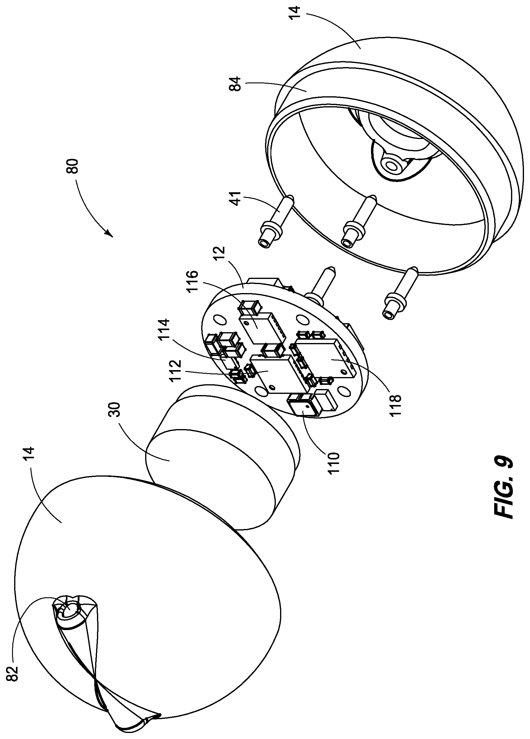
[0024] FIG. 9 is an alternative exploded view of the sensor assemblies of FIGS. 7 and 8 according to an embodiment of the disclosure.
[0025] FIG. 10 is a is a block diagram of electrically connected components of at least one assembly of the present disclosure.
DESCRIPTION
[0026] This disclosure is submitted in furtherance of the constitutional purposes of the U.S. Patent Laws "to promote the progress of science and useful arts" (Article 1, Section 8).
[0027] Referring first to FIG. 1A, at least one perspective view of a portion of a sensor assembly 10 is shown. In accordance with example implementations, sensor assembly 10 can include a circuit board 12 that is aligned in relation to housing 14. As shown, housing 14 can be substantially cylindrical in this view, and circuit board 12 may likewise be substantially cylindrical. In accordance with example implementations, the perimeter of circuit board 12 may compliment the cylindrical housing 14.
[0028] Referring next to FIG. 1B, housing 14 is shown in one cross section in relation to circuit board 12. As can be seen in this one cross section, perimeter plane 16 of circuit board 12 can be substantially parallel with perimeter plane 17 of housing 14. Further, opposing surfaces 18 of circuit board 12 can extend along a plane that is substantially normal to perimeter plane 17.
[0029] Referring next to FIGS. 2A and 2B, pressure sensor component 20 is shown in relation to circuit board 12 and housing 14. As shown, pressure sensor component 20 can reside within a recess 22 of housing 14. Referring next to FIGS. 3A and 3B, power source or battery 30 can be operatively aligned in relation to circuit board 12, on the opposing side of pressure sensor component 20, for example.
[0030] Referring next to FIG. 4, an isometric view of at least one sensor assembly 40 is shown that includes housing 14 about circuit board 12, with circuit board 12 supporting processing circuitry components including pressure sensor component 20 within recess 22. Additionally, pins 41 can extend through recesses 42. Pins 41 can be configured as an interface with processing circuitry components of sensor assembly 40. Further, power supply 30 such as a battery can be provided within housing 14 below circuit board 12 and opposing pressure sensor component 20. In this particular embodiment, sensor assembly 40 can include a base 44.
[0031] Referring next to FIGS. 5 and 6, alternative exploded views of sensor assembly 40 are shown that include circuit board 12 supporting pressure sensor component 20 above power source 30. Sensor assembly 40 can include light indicators 52 such as a green LED indicator. This indicator can be utilized to provide visual confirmation of the sensor assembly status, for example.
[0032] Additionally, sensor assembly 40 can include an amplifier 54 as well as a nine-axis inertial measurement component 56 and an accelerometer component 58. Amplifier 54 can be a pressure sensor amplifier component. The pressure sensor amplifier circuitry component can be a single component, and may occupy less than 3 mm.times.3 mm in area in all cross sections.
[0033] Additional light indicators can be provided as well. Accordingly, light indicator 60 can be provided as a blue LED, for example. In accordance with example implementations, housing 14 can be transparent or at least sufficiently translucent to allow for the viewing of the light indicators within sensor assembly 40.
[0034] Referring next to FIG. 6, on an alternate surface of circuit board 12 can be battery charger component 70, a memory component 62 such as a 64-megabit flash memory component, an oscillator component 64, a microcontroller 66, and a magnetic sensor component 68. As can be seen, assembly 40 can be within a substantially tubular housing having substantially planar ends. However, unlike the prior art sensor assemblies, the opposing surfaces of the circuit board are placed normal to the circular edges of the housing in at least one cross section.
[0035] According to example implementations, assembly 40 may have a height of 13.5 mm and a diameter of 18 mm in at least one cross section. Assembly 40 can occupy a volume of less than 3.76 cm3, and have a weight of less than 6.2 grams. Further, base 44 can be configured to be coupled to a flat rigid surface, e.g., a hydro turbine.
[0036] Referring next to FIG. 7, in accordance with another example implementation, sensor assembly 80 is shown that includes housing 14 about circuit board 12. In accordance with example implementations, housing 14 is substantially spherical and includes openings 42 and 22 to receive pins 41 and pressure sensor components 20. Additionally, assembly 80 can include a recess 82 configured to receive a self-inflating balloon.
[0037] Referring next to FIGS. 8 and 9, and first with respect to FIG. 8, assembly 80 is shown in an exploded view with housing 14 in two components that can be considered a bottom half and an upper half of the substantially spherical housing 14. In accordance with example implementations, at least one of the halves can have an extension 84 that is configured to be received by a recess or complimentary portion 86, allowing for a relatively sealed joining of the both top and bottom halves of housing 14. In accordance with example implementations, assembly 80 can include an amplifier 92 as well as a nine-axis inertial measurement unit 94 and an accelerometer component 96 as well as status indicating components 100 and 98 that may be represented as green and blue LEDs, respectively. Referring next to FIG. 9, on the opposing face of circuit board 12 can be a oscillator component 110 as well as a microcontroller 112, a magnetic sensor component 114 as well as a battery charger component 116 and a memory component such as a 64-megabit flash memory component 118.
[0038] According to example implementations, assembly 80 may have a maximum cross sectional diameter of 23.2 mm. Assembly 80 can occupy a volume of less than 6.38 cm3, and have a weight of less than 6.4 grams.
[0039] Referring lastly to FIG. 10, the electronics design of at least one of the sensor assemblies is shown in an overall block diagram. The design may contain one main circuit board that includes a microcontroller. This board is aligned as described above within housing 14 with the battery mounted within housing 14. The board and components of the assembly can be operably coupled to communication tool that includes serial download interface, and input to the battery charger. This communication tool can facilitate connection with or be a part of a docking station, not shown.
[0040] Power to the device can be provided by the battery which can be a lithium polymer battery. Example battery specifications can be, but are not limited to that of a CoinPower.RTM. CP 1254 A2 battery having a diameter: 12.1 mm, height: 5.4 mm, weight: 1.6 g, and capacity: 50 mAh. An integrated protection circuit cuts off the battery on an over-discharge condition.
[0041] A 3-axis accelerometer analog component with a typical full-scale range of .+-.200 g can be operationally coupled between the battery and the microcontroller. An example ADXL377 can be used; this particular component has approximate dimensions of 3.times.3.times.1.45 mm.
[0042] A nine--axis inertial measurement unit can also be operationally coupled between the battery and the microcontroller. This component may contain a 3-axis accelerometer, 3-axis gyroscope, and 3-axis magnetometer. An example InvenSense: MPU-9250; this particular component has approximate dimensions of 3.times.3.times.1 mm, has a shock tolerance of 10,000 g, consumes a supply current of 3.5 mA during operation, and includes an internal temperature sensor. For acceleration 16 g in operational range each axis can be achieved with 16 bits of precision. For rotation 2000.degree./s operational range in each axis can be achieved with 16 bits of precision. For magnetic sensing 4800 uT operational range in each axis can be achieved with 14 bits of precision. A sampling rate of 2048 samples per second can be achieved.
[0043] The pressure sensor can be an analog component with an operational range of 12 bar (174 psia). The positive and negative outputs may connect to the amplifier component before operationally coupling with the microcontroller. Example pressure sensors can include Measurement Specialties: MS5412BM with approximate dimensions of 6.2.times.6.4.times.2.88 mm.
[0044] Example amplifiers include the LT1991 with approximate dimensions of 3.times.3 mm.
[0045] The microcontroller component may be a Microchip: PIC24FJ64GA702 that includes: 2 I.sup.2C modules; 2 SPI modules; 2 UART modules; 12-bit and 200 ksps ADC; 64 kB Flash Program Memory; and 12 kB RAM. This component has approximate dimensions of 4.times.4.times.0.6 mm.
[0046] The memory component can be a Cypress: S25FL064LABNFl043 with capacity of 64 megabits and approximate dimensions of 4.times.4 mm.
[0047] To activate the device a magnetic sensor component can be operationally coupled to the microcontroller. In one embodiment, the magnetic sensor can be a Hall effect sensor. The magnetic sensor component can occupy 1.1.times.1.4 mm in all cross sections. The user may activate the sensor assembly by holding a magnet near the magnetic sensor. The output of the magnetic sensor may drive an interrupt pin of the microcontroller. LED lights may blink to indicate the system status.
[0048] The microcontroller can also activate an integrated RF beacon which generates a carrier signal, and drives an antenna. While the present embodiment is shown, it is to be understood that various other alternative embodiments are contemplated within the scope of the claims of the present application.
[0049] A docking station, not shown, can be used to charge the battery via power and ground connections on the download board, and downloads data from the microcontroller component. The data transfer may use RS-232 at 921.6 kHz baud rate, but with 3.0 V logic levels. The docking station may use a commercial TTL-to-USB converter cable or similar circuitry to pass the data to a personal computer. When the sensor assembly is placed in the docking station, the RS-232 signals may be pulled high to wake the microcontroller component from sleep mode.
[0050] The microcontroller component may contain firmware which provides the logic for operating the sensor assembly, whereas the other modules define the interfaces to various components with the necessary initialization routines. As stated above, the U.S. patent application Ser. No. 14/871,761 filed Sep. 30, 2015, entitled "Autonomous Sensor Fish to Support Advanced Hydropower Development", now U.S. Pat. No. 10,067,112 issued Sep. 4, 2018, is incorporated by reference herein, and can be relied upon for additional processing circuitry and execution detail.
[0051] In compliance with the statute, embodiments of the invention have been described in language more or less specific as to structural and methodical features. It is to be understood, however, that the entire invention is not limited to the specific features and/or embodiments shown and/or described, since the disclosed embodiments comprise forms of putting the invention into effect. The invention is, therefore, claimed in any of its forms or modifications within the proper scope of the appended claims appropriately interpreted in accordance with the doctrine of equivalents.
* * * * *
D00000
D00001
D00002
D00003
D00004
D00005
D00006
D00007
D00008
XML
uspto.report is an independent third-party trademark research tool that is not affiliated, endorsed, or sponsored by the United States Patent and Trademark Office (USPTO) or any other governmental organization. The information provided by uspto.report is based on publicly available data at the time of writing and is intended for informational purposes only.
While we strive to provide accurate and up-to-date information, we do not guarantee the accuracy, completeness, reliability, or suitability of the information displayed on this site. The use of this site is at your own risk. Any reliance you place on such information is therefore strictly at your own risk.
All official trademark data, including owner information, should be verified by visiting the official USPTO website at www.uspto.gov. This site is not intended to replace professional legal advice and should not be used as a substitute for consulting with a legal professional who is knowledgeable about trademark law.