System And Method For Network Communication Monitoring
Ling; Christopher ; et al.
U.S. patent application number 16/814308 was filed with the patent office on 2020-09-17 for system and method for network communication monitoring. The applicant listed for this patent is Arch Systems Inc.. Invention is credited to Timothy Matthew Burke, Luke Michael Ekkizogloy, Christopher Ling.
| Application Number | 20200296024 16/814308 |
| Document ID | / |
| Family ID | 1000004780171 |
| Filed Date | 2020-09-17 |


| United States Patent Application | 20200296024 |
| Kind Code | A1 |
| Ling; Christopher ; et al. | September 17, 2020 |
SYSTEM AND METHOD FOR NETWORK COMMUNICATION MONITORING
Abstract
A system for network communication monitoring, preferably including one or more network receivers, packet decoders, stream mergers, and/or memory. A method for network communication, preferably including receiving bitstreams, decoding packets, and/or merging packet streams.
| Inventors: | Ling; Christopher; (Mountain View, CA) ; Ekkizogloy; Luke Michael; (Mountain View, CA) ; Burke; Timothy Matthew; (Mountain View, CA) | ||||||||||
| Applicant: |
|
||||||||||
|---|---|---|---|---|---|---|---|---|---|---|---|
| Family ID: | 1000004780171 | ||||||||||
| Appl. No.: | 16/814308 | ||||||||||
| Filed: | March 10, 2020 |
Related U.S. Patent Documents
| Application Number | Filing Date | Patent Number | ||
|---|---|---|---|---|
| 62817384 | Mar 12, 2019 | |||
| Current U.S. Class: | 1/1 |
| Current CPC Class: | H04B 1/16 20130101; H04L 69/22 20130101; H04L 43/106 20130101; H04L 12/40 20130101 |
| International Class: | H04L 12/26 20060101 H04L012/26; H04B 1/16 20060101 H04B001/16; H04L 29/06 20060101 H04L029/06; H04L 12/40 20060101 H04L012/40 |
Claims
1. A system for monitoring network communications on a field bus, the system comprising: a clock generator; a memory module; a first network receiver communicatively coupled to a first signal transmission element of the field bus; a second network receiver communicatively coupled to a second signal transmission element of the field bus; a first packet decoder communicatively coupled to the first network receiver, the clock generator, and the memory module, wherein the first packet decoder: receives a first bitstream from the first network receiver; receives a clock signal from the clock generator; generates a first plurality of timestamped packets based on the first bitstream and the clock signal, wherein each timestamped packet of the first plurality is associated with a respective timestamp; and outputs the first plurality of timestamped packets to the memory module; a second packet decoder communicatively coupled to the second network receiver, the clock generator, and the memory module, wherein the second packet decoder: receives a second bitstream from the second network receiver; receives the clock signal from the clock generator; generates a second plurality of timestamped packets based on the second bitstream and the clock signal, wherein each timestamped packet of the second plurality is associated with a respective timestamp; and outputs the second plurality of timestamped packets to the memory module; and a stream merger communicatively coupled to the memory module, wherein the stream merger: receives the first and second pluralities of timestamped packets from the memory module; and based on the respective timestamps of the first and second pluralities of timestamped packets, generates a merged stream of chronologically ordered packets.
2. The system of claim 1, further comprising an wherein the first packet decoder, the second packet decoder, the stream merger, and the memory module are collocated within an integrated circuit package.
3. The system of claim 2, wherein the first packet decoder, the second packet decoder, the stream merger, and the memory module are collocated on a single die within the integrated circuit package.
4. The system of claim 1, further comprising a plurality of processing units that cooperatively implement the first packet decoder, the second packet decoder, and the stream merger.
5. The system of claim 4, wherein the plurality of processing units comprises at least one real-time CPU that implements the first packet decoder and the second packet decoder.
6. The system of claim 5, wherein the plurality of processing units comprises: a first real-time CPU that implements the first packet decoder; a second real-time CPU that implements the second packet decoder; and a third CPU that implements the stream merger.
7. The system of claim 1, wherein: the first signal transmission element comprises a first electrical conductor; the first network receiver is electrically coupled to and samples a first voltage associated with the first electrical conductor; the second signal transmission element comprises a second electrical conductor; and the second network receiver is electrically coupled to and samples a second voltage associated with the second electrical conductor.
8. The system of claim 7, wherein: the first network receiver comprises a first physical layer receiver circuit associated with an Ethernet physical layer transmission standard, wherein the first physical layer receiver circuit samples the first voltage; and the second network receiver comprises a second physical layer receiver circuit associated with the Ethernet physical layer transmission standard, wherein the second physical layer receiver circuit samples the second voltage.
9. The system of claim 8, wherein: the Ethernet physical layer transmission standard is an Ethernet 100BASE-T physical layer transmission standard; the field bus comprises a 100BASE-TX Ethernet line; and the 100BASE-TX Ethernet line comprises the first and second electrical conductors.
10. The system of claim 7, wherein: voltage signals transmitted along the first signal transmission element propagate past the first network receiver substantially without alteration; and voltage signals transmitted along the second signal transmission element propagate past the second network receiver substantially without alteration.
7. system of claim 7, wherein: the first electrical conductor and the first network receiver cooperatively define a first electrical T junction; and the second electrical conductor and the second network receiver cooperatively define a second electrical T junction.
12. A method for monitoring network communications on a field bus, the method comprising: throughout a time period: passively receiving a first set of signals from a first signal transmission element of the field bus; passively receiving a second set of signals from a second signal transmission element of the field bus; and receiving a clock signal; based on the first set of signals, generating a first bitstream; based on the second set of signals, generating a second bitstream; generating a first plurality of timestamped packets based on the first bitstream and the clock signal, wherein each packet of the first plurality is associated with a respective timestamp; generating a second plurality of timestamped packets based on the second bitstream and the clock signal, wherein each packet of the second plurality is associated with a respective timestamp; and generating a merged stream of chronologically-ordered packets, comprising, based on the timestamps associated with the packets of the first and second pluralities, chronologically ordering the packets of the first and second pluralities.
13. The method of claim 12, wherein: the first set of signals continues along the first signal transmission element substantially unchanged and substantially without delay; and the second set of signals continues along the second signal transmission element substantially unchanged and substantially without delay.
14. The method of claim 12, wherein: the first set of signals comprises every signal received from the first signal transmission element; the second set of signals comprises every signal received from the second signal transmission element; the first plurality of timestamped packets is indicative of every signal of the first set of signals; and the second plurality of timestamped packets is indicative of every signal of the second set of signals.
15. The method of claim 14, wherein the merged stream comprises each packet of the first and second pluralities.
16. The method of claim 12, wherein: each packet of the first plurality is generated based on a respective window of the first bitstream; each packet of the second plurality is generated based on a respective window of the second bitstream; and for each packet of the first and second pluralities, the respective timestamp is associated with a respective time at which the respective window was passively received.
17. The method of claim 12, wherein the first set of signals is associated with an Ethernet physical layer transmission standard, wherein the first set of signals defines: a bit time greater than 5 ns; and an inter-frame gap of less than 96 bit times.
12. method of claim 12, wherein the first set of signals is associated with an Ethernet physical layer transmission standard, wherein the first plurality of timestamped packets comprises a packet of less than 64 bytes.
19. The method of claim 12, wherein the first set of signals is associated with an Ethernet physical layer transmission standard, wherein the first plurality of timestamped packets comprises a packet that does not comprise a start frame delimiter.
20. The method of claim 19, wherein the packet is generated based on a window of the first bitstream, wherein the packet comprises a 0x5 nibble immediately preceding a 0xD nibble, wherein generating the first plurality of timestamped packets comprises: determining a mismatch between the window and a checksum associated with the window; in response to determining the mismatch, inserting the 0xD nibble immediately following the 0x5 nibble to generate a modified window; determining a match between the modified window and the checksum; and in response to determining the match, generating the packet based on the modified window.
Description
CROSS-REFERENCE TO RELATED APPLICATIONS
[0001] This application claims the benefit of U.S. Provisional Application Ser. No. 62/817,384, filed on 12 Mar. 2019, which is incorporated in its entirety by this reference.
TECHNICAL FIELD
[0002] This invention relates generally to the network communication field, and more specifically to a new and useful system and method for network communication monitoring.
BACKGROUND
[0003] Typical systems for network communication monitoring exhibit one or more important limitations. A first class of such systems actively tap signal transmission elements, which can produce undesirable effects for the signals transmitted on those signal transmission elements, such as interruptions (e.g., when the active tap is unpowered, deactivated, and/or in a failure state) and/or delays. A second class of such systems passively tap signal transmission elements, but are incapable of aggregating signals from multiple such elements into a single stream. A third class of such systems (e.g., Hilscher ANL-B500G-RE) can aggregate signals from multiple signal transmission elements, but require that these signals exhibit one or more "Layer 2" characteristics of IEEE 802.3 Ethernet standards.
[0004] Thus, there is a need in the network communication field to create a new and useful system and method for network communication monitoring.
BRIEF DESCRIPTION OF THE FIGURES
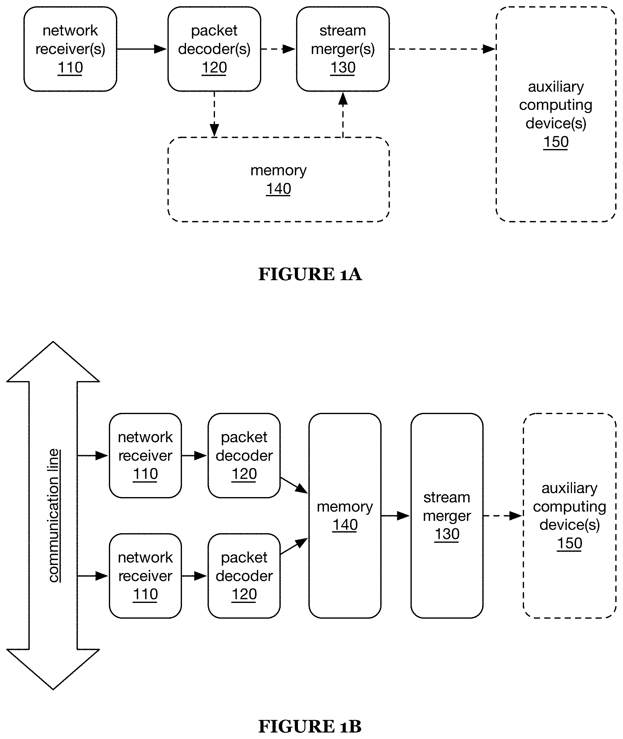
[0005] FIG. 1A is a schematic representation of an embodiment of the system.
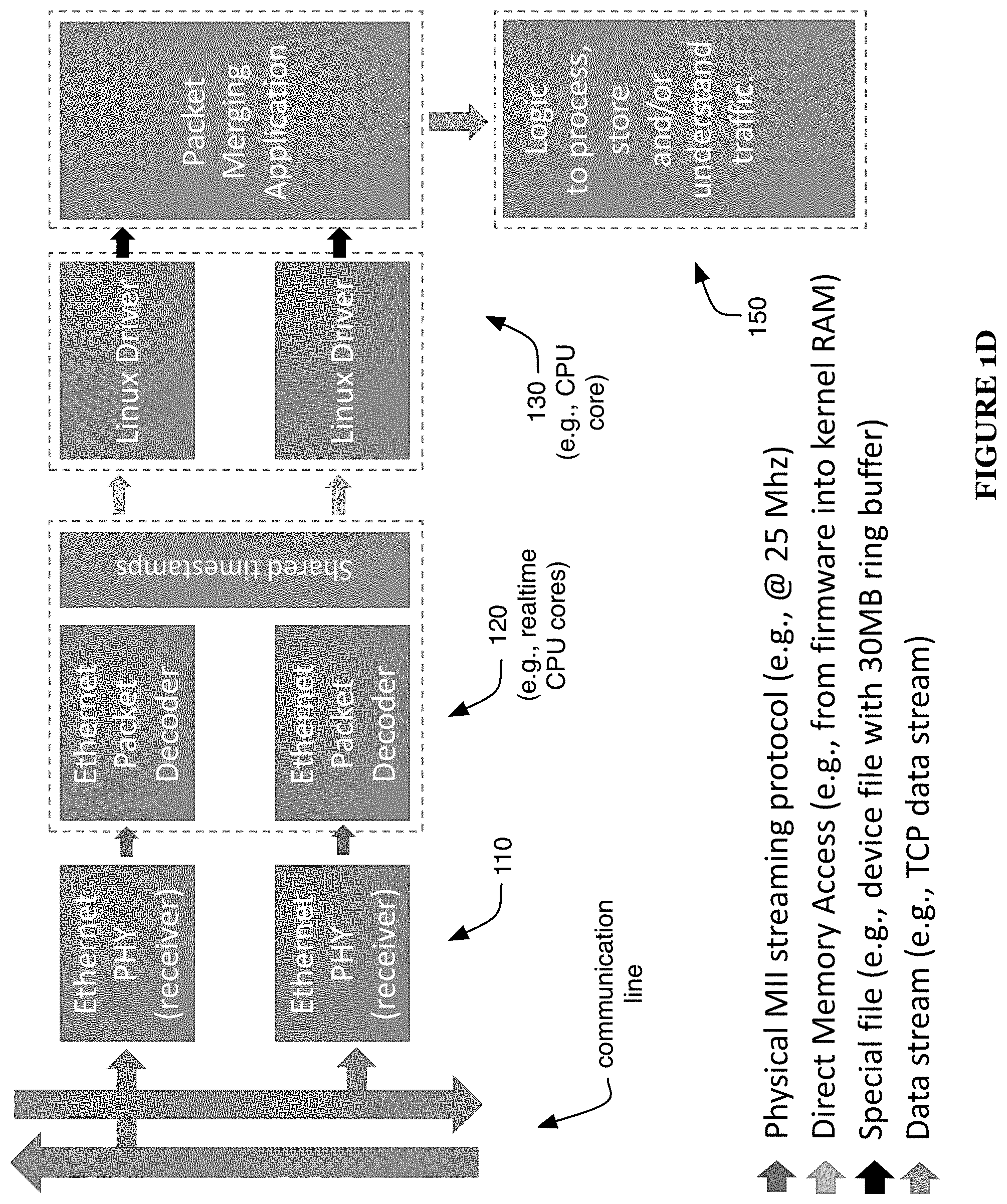
[0006] FIGS. 1B-1D are schematic representations of examples of the embodiment of the system.
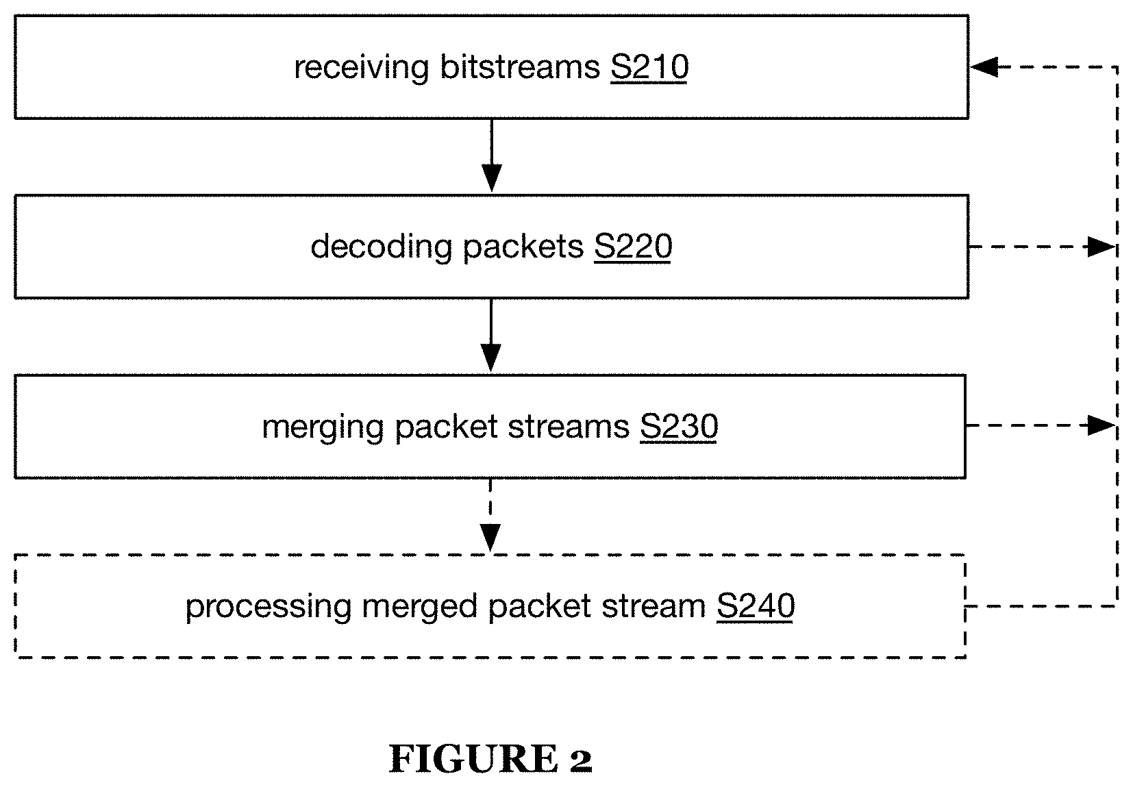
[0007] FIG. 2 is a schematic representation of an embodiment of the method.
[0008] FIG. 3 is a schematic representation of an example environment of the system.
[0009] FIG. 4 is a schematic representation of an example of network receivers of the system.
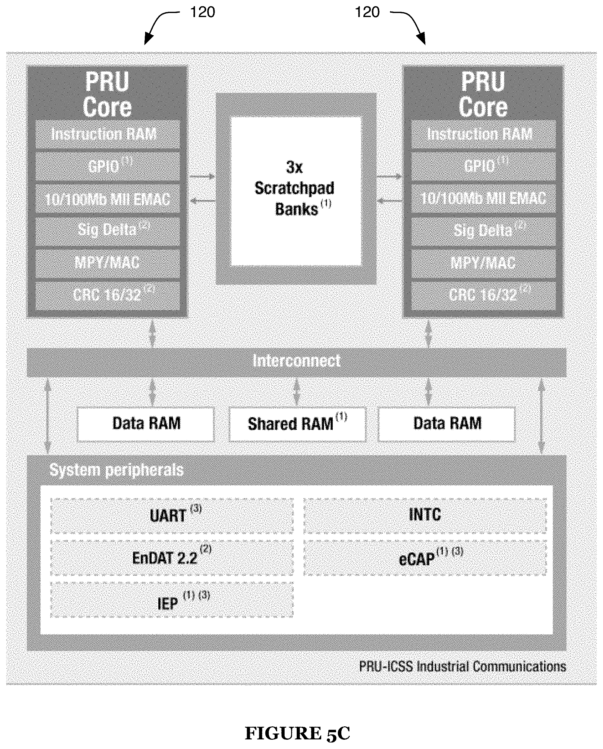
[0010] FIGS. 5A-5B are schematic representations of an embodiment and an example, respectively, of a multi-core processor.
[0011] FIG. 5C is a schematic representation of an example of packet decoders of the multi-core processor.
DESCRIPTION OF THE PREFERRED EMBODIMENTS
[0012] The following description of the preferred embodiments of the invention is not intended to limit the invention to these preferred embodiments, but rather to enable any person skilled in the art to make and use this invention.
1. Overview
[0013] A system 100 for network communication monitoring preferably includes one or more: network receivers 110, packet decoders 120, stream mergers 130, and/or memory 140 (e.g., as shown in FIGS. 1A-1B). The system 100 can optionally include one or more auxiliary computer devices 150. A method 200 for network communication preferably includes: receiving bitstreams S210, decoding packets S220, and/or merging packet streams S230 (e.g., as shown in FIG. 2). The method 200 can optionally include processing the merged packet stream S240. However, the system 100 and/or method 200 can additionally or alternatively include any other suitable elements.
2. Benefits
[0014] The system and/or method for network communication monitoring can confer one or more benefits.
[0015] First, embodiments of the system and/or method can monitor signals propagating along one or more signal transmission elements without deleterious interference with those signals. For example, the signals can preferably be monitored without substantially delaying (e.g., not delaying by more than a threshold amount, such as 1, 2, 5, 10, 20, 50, 100, 200, 500, 1000, 0.1-1, 1-10, 10-100, 100-1000, or 1000-10,000 ns, etc.) propagation of the signals along the signal transmission element(s). Additionally or alternatively, use of the system and/or method preferably does not result in interruption of signal propagation (e.g., causing the signals not to propagate along the signal transmission element(s)), even in situations in which the system is in an atypical or failure state (e.g., unpowered, deactivated, functioning erroneously, etc.).
[0016] Second, embodiments of the system and/or method can aggregate monitored signals from multiple signal transmission elements, preferably while substantially maintaining a chronological ordering of such signals. For example, if the system and/or method is used to monitor both directions of a bidirectional communication line (e.g., CAT5 or CAT6 cable), the system and/or method can aggregate signals propagating in both directions along the communication line and preserve their chronological order (e.g., such that a query, sent in one direction along the communication line, appears before a response to the query, sent in the other direction along the communication line after receipt of the query).
[0017] Third, embodiments of the system and/or method can monitor signals that do not exhibit some or all "Layer 2" characteristics of a signal transmission standard, such as IEEE 802.3 Ethernet standards. For example, the system and/or method can monitor signals that conform to the portions of one or more such standards associated with "Layer 1" behavior, but not to some or all portions associated with "Layer 2" behavior. In specific examples, such signals can exhibit one or more of: packet sizes less than 64 bytes, inter-frame gaps of less than 960 ns and/or less than 96 bit times, preambles of less than 7 bytes, absence of elements such as preambles, start frame delimiters, and/or frame check sequences, and/or presence of elements not found in standard Ethernet packets. However, the signals can additionally or alternatively exhibit any other suitable characteristics.
[0018] The system and/or method can additionally or alternatively confer any other suitable benefits.
3. System
3.1 Network Receiver
[0019] The network receiver 110 preferably functions to receive a communication bitstream (e.g., from a communication medium, such as one or more communication lines of a field bus and/or any other suitable communication lines). The communication bitstream is preferably received from a signal transmission element, which is preferably an element associated with a single signal stream. For example, in a communication line (e.g., CAT5 or CAT6 cable) that includes multiple pairs of wires, wherein each pair of wires is associated with a single stream of communication signals, each such pair of wires can be considered a separate signal transmission element.
[0020] The network receiver is preferably a passive tap. The network receiver preferably imposes no delay (or substantially no delay, such as a delay of less than 0.1, 0.2, 0.5, 1, 2, 5, 10, 0.01-0.1, 0.1-0.5, 0.3-1, 0.5-2, 1-3, or 3-30 .mu.s) on the bitstream propagating along the line (e.g., the field bus). The network receiver preferably does not interrupt (e.g., prevent propagation of) transmissions along the medium (e.g., line), even if the system 100 and/or a portion thereof (e.g., the network receiver) fails (e.g., loses power, functions erroneously, etc.). The network receiver preferably does not generate any output on the line (e.g., is not configured to generate any output, is not capable of generating any output, etc.). Alternatively, the network receiver can include an active tap (e.g., implementing a store-and-forward tapping process) and/or any other suitable taps.
[0021] The system preferably includes two network receivers 110, wherein each receiver taps the transmission line(s) associated with one direction of network traffic. Thus, the two receivers can be used together to capture bidirectional traffic between two network devices (e.g., between two endpoints; between a controller and a device hub or network switch, such as a hub or switch connected to some or all other devices of a machine; etc.; such as shown in FIG. 3). Alternatively, the system can include more than two receivers (e.g., capturing traffic between more than two network devices), can include a single receiver (e.g., capturing only unidirectional traffic, solely responsible for capturing bidirectional traffic, etc), and/or can include any other suitable number of receivers.
[0022] The network receiver preferably includes physical layer receiver circuitry (e.g., associated with one or more physical layer transmission standards, such as Ethernet 100BASE-T, any other Ethernet standard, and/or any other suitable standard, etc.). The network receiver preferably includes one or more wires or other conductors (e.g., defining one or more electrical T-junctions, such as shown in FIG. 4) coupling the receiver circuitry to the transmission lines (e.g., to each wire and/or other conductor of the transmission lines, to the subset of conductors associated with transmission in a particular direction, etc.). Such an electrical configuration can enable the receiver circuitry to sample the voltage of each conductor of the transmission lines (e.g., in a 100BASE-TX Ethernet line, the two conductors of the transmit pair and the two conductors of the receive pair). However, the network receiver 110 can additionally or alternatively include any other suitable elements in any suitable arrangement.
3.2 Packet Decoder
[0023] The packet decoder 120 preferably functions to convert a bitstream (e.g., received by the network receiver) into packets (e.g., timestamped packets). The system preferably includes one packet decoder 120 for each network receiver no (e.g., one packet decoder coupled to and/or receiving a bitstream from each network receiver). The packet decoder preferably includes one or more real-time computing elements. For example, the packet decoder can include one or more CPUs (or CPU cores), preferably real-time CPUs or CPU cores, ASICs, FPGAs, and/or any other suitable computing circuitry. The packet decoder 120 preferably shares a clock signal with one or more other packet decoders (e.g., with the other packet decoder(s) of the system, etc.). This shared clock signal can enable use of a shared timestamp reference (e.g., for packets in the different bitstreams), thereby facilitating downstream merging of the different packet streams (e.g., by the stream merger 130. However, the packet decoder 120 can additionally or alternatively include any other suitable elements in any suitable arrangement.
[0024] The packet decoder is preferably configured to and/or capable of processing each packet within a packet time interval (e.g., actual or minimum packet duration time, time between the start or end of consecutive packets, etc.), such as processing the packet before arrival of the next packet and/or processing packets while satisfying a zero-backpressure condition (e.g., wherein the rate of incoming packets from the bitstream cannot be reduced, wherein the packet decoder does not drop any packets, etc.). For example, for a bitstream with a rate of 10 ns/bit (e.g., transmitted on a 100BASE-T Ethernet communication line) and a minimum packet size of six bytes (e.g., associated with a VARAN bitstream), each packet is preferably capable of being processed by the packet decoder within the 480 ns interval associated with the minimum packet size. For a 200 MHz decoder CPU, this corresponds to processing each packet within 96 clock cycles (e.g., using no more than 96 instructions).
[0025] The packet decoder preferably writes the processed packets (e.g., timestamped packets) to the memory 140. However, the packet decoder can additionally or alternatively store and/or provide the processed packets in any other suitable manner.
3.3 Stream Merger
[0026] The stream merger 130 preferably functions to generate a merged packet stream. The stream merger preferably merges packets from multiple streams (e.g., from both receivers and/or decoders) into a single stream (e.g., chronologically ordered stream). The stream merger preferably includes one or more general purpose computing elements (e.g., CPUs and/or CPU cores), but can additionally or alternatively include real-time CPUs and/or CPU cores, ASICs, FPGAs, and/or any other suitable computing elements.
[0027] The stream merger is preferably configured to read packets from memory (e.g., from the memory 140 to which the packet decoders write), but can additionally or alternatively receive packet streams from any other suitable sources. The stream merger 130 preferably provides the merged packet stream to one or more downstream consumers (e.g., the auxiliary computing device(s) 150, but can additionally or alternatively provide the packet streams in any other suitable manner. For example, the stream merger can be communicatively coupled to an auxiliary computing device, such as by a network communication system (e.g., wired communication lines, wireless communication units, etc.). However, the stream merger 130 can additionally or alternatively include any other suitable elements in any suitable arrangement.
3.4 Memory
[0028] The memory 140 is preferably RAM, more preferably fast random access memory (e.g., processor cache memory, SRAM, etc.) but alternatively any other suitable RAM (or any other suitable computing memory). The memory 140 is preferably shared between the stream merger 130 and all packet decoders 120 of the system. However, the memory can additionally or alternatively be shared between any other suitable elements, can be dedicated to individual elements (e.g., partitioned between the individual packet decoders and/or stream merger, such as wherein one element does not read from and/or write to a partition associated with a different element), and/or can be distributed in any other suitable manner.
3.5 Auxiliary Computing Device
[0029] The auxiliary computing device 150 can function to perform computations, such as data analysis, filtering, modification, and/or storage. These operations are preferably performed based on the merged packet stream (e.g., the packet stream received from the stream merger 130). For example, the auxiliary computing device can perform one or more operations such as described in U.S. patent application Ser. No. 16/218,164, titled "System and Method for Physical Machine Monitoring and Analysis" and filed 12 Dec. 2018, which is hereby incorporated in its entirety by this reference (e.g., as described below, such as regarding S240).
[0030] The auxiliary computing device can include one or more processors (e.g., CPU, GPU, microprocessor, FPGA, ASIC, etc.), computers, and/or data storage elements (e.g., Flash, RAM, magnetic disk drive, etc.), but can additionally or alternatively include any other suitable elements. The auxiliary computing device preferably receives the merged packet stream (e.g., from the stream merger 130), such as via shared memory, communication link (e.g., TCP link), and/or in any other suitable manner. However, the auxiliary computing device 150 can additionally or alternatively include any other suitable elements in any other suitable arrangement.
3.6 Examples
[0031] In a first example (e.g., as shown in FIGS. 1C-1D), the system 100 includes two network receivers (e.g., each network receiver including physical layer receiver circuitry, such as for Ethernet communications); two real time CPUs or CPU cores in a one-to-one pairing with the receivers (e.g., wherein each accepts a bitstream from a different receiver) and sharing a single clock; a general purpose CPU or CPU core; and memory (e.g., RAM) shared between the real-time CPUs and general purpose CPU. In a specific example (e.g., as shown in FIGS. 5A-5C), the system includes two real-time CPU cores, a general purpose CPU core (e.g., an ARM core), and shared memory (e.g., processor cache) all in the same package and/or on the same die (e.g., as a single integrated circuit); for example, these elements can be included in a multi-core processor such as in the Texas Instruments Sitara.TM.0 product line (e.g., Sitara.TM. AM335X product line, such as the AM3356, AM3357, AM3358, and/or AM3359.
[0032] In an alternative example, a single element (e.g., a real-time CPU) can function as both packet decoders 120 (or optionally, in embodiments including more than two packet decoders, as all the packet decoders or any suitable subset thereof). In this example, this element can optionally also function as the stream merger 130. This element preferably receives bitstreams from each network receiver and converts both bitstreams into timestamped packets, and can optionally merge these timestamped packets into a single packet stream.
[0033] However, the system 100 can additionally or alternatively include any other suitable elements in any suitable configuration.
4. Method
[0034] The method 200 is preferably implemented using the system 100 described above, but can additionally or alternatively be implemented using any other suitable system(s).
4.1 Receiving Bitstreams
[0035] Receiving bitstreams S210 is preferably performed by one or more network receivers (e.g., each network receiver of the system). Each bitstream (e.g., Fieldbus bitstream) is preferably an MII bitstream (e.g., traffic conforming to Ethernet Layer 1 standards, MII traffic such as described in the Appendix, etc.), but can additionally or alternatively include any other suitable bitstreams. For example, the bitstreams can be bitstreams of a communication system such as: Ethernet (e.g., Fast Ethernet), EtherCAT, VARAN, GPIB, Bitbus, RS-232, Centronics, IEEE 1284, RJ11, USB, and/or any other suitable network communication system.
[0036] The bitstreams may or may not conform to one or more Ethernet specifications (e.g., one or more of the IEEE 802.3 standards, which are hereby incorporated in their entireties by this reference; as described in the Appendix; etc.), such as to the portions of the specifications associated with Layer 1 (physical layer) behavior, Layer 2 (data link layer) behavior, etc. In some embodiments, the bitstreams may exhibit atypical characteristics (e.g., Layer 2 characteristics) compared to a standard Ethernet bitstream. For example, the bitstreams may include a minimum packet size less than 64 bytes (e.g., 1, 2, 4, 6, 8, 16, 32, 1-4, 4-8, 8-16, or 16-64 bytes), a minimum inter-frame gap less than 960 ns and/or less than 96 bit times (e.g., 0, 80, 160, 320, 640, 0-80, 80-320, or 320-960 ns; 0, 8, 16, 32, 64, 0-8, 8-32, or 32-96 bit times; etc.), and/or a minimum preamble of less than 7 bytes (e.g., 0, 1, 2, 4, 6, 0-1, 1-3, or 3-7 bytes); may include no start frame delimiter (SFD) and/or frame check sequence (FCS); may include elements (e.g., start- and/or end-of-frame elements) not found in standard Ethernet packets; and/or may exhibit any other suitable characteristics.
[0037] The bitstreams preferably exhibit bit times greater than 5 ns (e.g., substantially 10 ns, such as for 100 Mb/s Ethernet or "Fast Ethernet"; substantially 100 ns such as for 10 Mb/s Ethernet; etc.), but can additionally or alternatively exhibit bit times less than or equal to 5 ns (e.g., substantially 1 ns, such as for 1 Gb/s Ethernet or "Gigabit Ethernet"; substantially less than 1 ns; etc.) and/or any other suitable bit times.
[0038] The bitstreams are preferably received continuously (e.g., whenever transmissions are sent along the communication line), but can additionally or alternatively be received periodically, sporadically, in response to trigger events, and/or with any other suitable timing. However, S210 can additionally or alternatively include receiving bitstreams in any other suitable manner.
4.2 Decoding Packets
[0039] Decoding packets S220 is preferably performed at the packet decoder or decoders (e.g., for a given bitstream, performed at the packet decoder associated with the network receiver at which the bitstream is received). S220 is preferably performed continuously (e.g., whenever S210 is performed), but can additionally or alternatively be performed periodically, sporadically, in response to trigger events, and/or with any other suitable timing.
[0040] S220 preferably includes: parsing the bitstream into packets; associating each packet with a time stamp (e.g., based on a shared clock signal); and/or storing the packets (e.g., in shared memory). S220 can optionally include correcting parse errors (e.g., before storing the packets). For example, S220 can include detecting and/or correcting parse errors created due to inappropriate assumptions (e.g., encoded in hardware, firmware, and/or software subsystems of the packet decoder 120), such as assumptions associated with Layer 2 characteristics of the bitstream (e.g., assumptions that the bitstream will conform to one or more characteristics associated with behavior under one or more of the 802.3 standards, such as characteristics described in the Appendix).
[0041] In one example, when a bitstream includes a 0x5 nibble followed by a 0xD nibble (e.g., X5 DY, for arbitrary nibbles X and Y) this nibble sequence may be misinterpreted (e.g., by the hardware) as an SFD byte (e.g., misaligned SFD byte), which is typically the 0x5D byte. This misinterpretation can result in a corrupted bitstream. For example, the packet decoder may drop the 0xD nibble, causing all following byte boundaries to be misaligned. The hardware may additionally or alternatively drop the final nibble (e.g., when the packet ends with a checksum, the final nibble of the checksum, such as the second nibble of the second byte of a CRC-16 checksum), such as due to this byte boundary misalignment. In this example, correcting parse errors can include performing a packet checksum test (e.g., in examples in which the second checksum byte is dropped, performing the test based only on the first checksum byte). If the packet checksum test fails, correcting parse errors can include attempting to insert a 0xD nibble at various locations in the parsed packet to generate a candidate packet, and performing the checksum test on the candidate packet(s) (e.g., inserting the nibble at each of a variety of different locations, preferably until a candidate packet is determined for which the checksum test is passed). For example, the 0xD nibble can be inserted after any 0x5 nibbles, after 0x5 nibbles that appear as the second nibble of a byte (e.g., appearing in such positions in the corrupted packet), and/or in any other suitable locations.
[0042] However, S220 can additionally or alternatively include decoding packets in any other suitable manner.
4.3 Merging Packet Streams
[0043] Merging the packet streams S230 is preferably performed at the stream merger. S230 preferably includes merging timestamped packets (e.g., packets from multiple streams, such as the streams generated in S220) into a single stream (e.g., chronologically-ordered packet stream). S230 can include writing the generated stream to memory and/or other storage, transmitting the stream to one or more auxiliary computing devices, and/or providing the stream in any other suitable manner.
[0044] In one example (e.g., in which the stream merger includes a CPU running a general purpose operating system, such as an ARM CPU core running Linux), S230 can include: at one or more drivers (e.g., one driver associated with each packet decoder), presenting the timestamped packets (e.g., written by the packet decoder) to a merging application. For example, each driver can place the timestamped packets into a buffer (e.g., dedicated buffer for each driver), which can facilitate rate matching (e.g., between the packet streams). The buffer is preferably a ring buffer, but can additionally or alternatively include one or more buffers of any other suitable types. The buffer is preferably megabyte-scale (e.g., 1, 2, 5, 10, 20, 30, 40, 60, 100, 200, 500, 1-3, 3-10, 10-30, 20-50, 30-100, or 100-1000 MB), but can alternatively have any other suitable capacity (e.g., 1-10, 10-100, or 100-1000 kB; 1-3, 3-10, or 10-30 GB; less than 1 kB, more than 30 GB; etc.). The buffer can be presented as a device file (or special file), and/or can be accessible (e.g., to the merging application) in any other suitable manner. The drivers preferably use direct memory access (DMA) to access the timestamped packets (e.g., the packets written to shared memory in S220), but can additionally or alternatively receive the packets in any other suitable manner. In this example, the merging application preferably receives timestamped packets from each driver and merges them into a single packet stream (e.g., accepting the timestamped packets and merging them into a chronologically-ordered packet stream).
[0045] S230 is preferably performed continuously (e.g., whenever S220 is performed). However, some or all of S230 can additionally or alternatively be performed periodically, sporadically, in response to trigger events, and/or with any other suitable timing. In one example, the drivers preferably place packets into the buffer(s) continuously, substantially continuously, periodically, and/or in response to trigger events such as whenever packets are available (e.g., packets that have not yet been placed into the buffer) and/or exceed a storage threshold, but alternatively with any other suitable timing; and the merging application can run continuously, substantially continuously, periodically, sporadically, in response to trigger events (e.g., one or more buffers exceeding a storage threshold, such as a percentage of total buffer storage volume), and/or with any other suitable timing.
[0046] However, S230 can additionally or alternatively include merging the packet streams in any other suitable manner.
4.4 Processing the Merged Stream
[0047] Processing the merged stream S240 is preferably performed by one or more auxiliary computing devices, but can additionally or alternatively be performed by any other suitable elements. S240 can be performed continuously, substantially continuously, periodically, sporadically, in response to trigger events (e.g., receipt of data, such as receipt of packets in the merged packet stream), and/or with any other suitable timing.
[0048] S240 (and/or any other suitable elements of the method 200) can include one or more elements such as described in U.S. patent application Ser. No. 16/218,164, titled "System and Method for Physical Machine Monitoring and Analysis" and filed 12 Dec. 2018, which is hereby incorporated in its entirety by this reference (e.g., wherein receiving transmissions supplied to a physical machine S100 of U.S. patent application Ser. No. 16/218,164 can include receiving the bitstreams, such as described above regarding S210, receiving the merged stream, such as at the auxiliary computing device(s), and/or receiving any other suitable information associated with the transmissions). However, S240 can additionally or alternatively include processing the merged stream in any other suitable manner.
[0049] However, the method 200 can additionally or alternatively include any other suitable elements performed in any suitable manner.
[0050] Although omitted for conciseness, the preferred embodiments include every combination and permutation of the various system components and the various method processes. Furthermore, various processes of the preferred method can be embodied and/or implemented at least in part as a machine configured to receive a computer-readable medium storing computer-readable instructions. The instructions are preferably executed by computer-executable components preferably integrated with the system. The computer-readable medium can be stored on any suitable computer readable media such as RAMs, ROMs, flash memory, EEPROMs, optical devices (CD or DVD), hard drives, floppy drives, or any suitable device. The computer-executable component is preferably a general or application specific processing subsystem, but any suitable dedicated hardware device or hardware/firmware combination device can additionally or alternatively execute the instructions.
[0051] The FIGURES illustrate the architecture, functionality and operation of possible implementations of systems, methods and computer program products according to preferred embodiments, example configurations, and variations thereof. In this regard, each block in the flowchart or block diagrams may represent a module, segment, step, or portion of code, which comprises one or more executable instructions for implementing the specified logical function(s). It should also be noted that, in some alternative implementations, the functions noted in the block can occur out of the order noted in the FIGURES. For example, two blocks shown in succession may, in fact, be executed substantially concurrently, or the blocks may sometimes be executed in the reverse order, depending upon the functionality involved. It will also be noted that each block of the block diagrams and/or flowchart illustration, and combinations of blocks in the block diagrams and/or flowchart illustration, can be implemented by special purpose hardware-based systems that perform the specified functions or acts, or combinations of special purpose hardware and computer instructions.
[0052] As a person skilled in the art will recognize from the previous detailed description and from the figures and claims, modifications and changes can be made to the preferred embodiments of the invention without departing from the scope of this invention defined in the following claims.
* * * * *
D00000
D00001
D00002
D00003
D00004
D00005
D00006
D00007
XML
uspto.report is an independent third-party trademark research tool that is not affiliated, endorsed, or sponsored by the United States Patent and Trademark Office (USPTO) or any other governmental organization. The information provided by uspto.report is based on publicly available data at the time of writing and is intended for informational purposes only.
While we strive to provide accurate and up-to-date information, we do not guarantee the accuracy, completeness, reliability, or suitability of the information displayed on this site. The use of this site is at your own risk. Any reliance you place on such information is therefore strictly at your own risk.
All official trademark data, including owner information, should be verified by visiting the official USPTO website at www.uspto.gov. This site is not intended to replace professional legal advice and should not be used as a substitute for consulting with a legal professional who is knowledgeable about trademark law.