Device For Inductively Transferring Electrical Energy And/or Data, And Method For Producing Such A Device
HEINRICH; Joerg ; et al.
U.S. patent application number 16/817772 was filed with the patent office on 2020-09-17 for device for inductively transferring electrical energy and/or data, and method for producing such a device. This patent application is currently assigned to Balluff GmbH. The applicant listed for this patent is Balluff GmbH, Universitaet Stuttgart. Invention is credited to Joerg HEINRICH, David MAIER, Nejila PARSPOUR.
| Application Number | 20200295599 16/817772 |
| Document ID | / |
| Family ID | 1000004720483 |
| Filed Date | 2020-09-17 |


| United States Patent Application | 20200295599 |
| Kind Code | A1 |
| HEINRICH; Joerg ; et al. | September 17, 2020 |
DEVICE FOR INDUCTIVELY TRANSFERRING ELECTRICAL ENERGY AND/OR DATA, AND METHOD FOR PRODUCING SUCH A DEVICE
Abstract
A device for inductively transferring electrical energy and/or data from a primary-sided carrier to at least one positionable secondary-sided recipient includes at least one primary-sided coil arrangement, which inductively interacts with at least one secondary-sided coil arrangement. Meander-shaped windings of a predeterminable winding number of the primary-sided and/or secondary-sided coil arrangement are arranged on at least one flexible carrier by embroidering a high frequency strand, and the meander-shaped windings have straight courses in the region of crossovers of the embroidered high frequency strands.
| Inventors: | HEINRICH; Joerg; (Duerrlewang, DE) ; MAIER; David; (Buehl, DE) ; PARSPOUR; Nejila; (Gerlingen, DE) | ||||||||||
| Applicant: |
|
||||||||||
|---|---|---|---|---|---|---|---|---|---|---|---|
| Assignee: | Balluff GmbH Neuhausen a.d.F. DE Universitaet Stuttgart Stuttgart DE |
||||||||||
| Family ID: | 1000004720483 | ||||||||||
| Appl. No.: | 16/817772 | ||||||||||
| Filed: | March 13, 2020 |
| Current U.S. Class: | 1/1 |
| Current CPC Class: | H02J 50/10 20160201; H04B 5/0081 20130101; H04B 5/0031 20130101; H02J 50/80 20160201; H01F 27/2804 20130101; H04B 5/0037 20130101; H02J 50/70 20160201 |
| International Class: | H02J 50/10 20060101 H02J050/10; H02J 50/80 20060101 H02J050/80; H02J 50/70 20060101 H02J050/70; H04B 5/00 20060101 H04B005/00; H01F 27/28 20060101 H01F027/28 |
Foreign Application Data
| Date | Code | Application Number |
|---|---|---|
| Mar 15, 2019 | DE | 10 2019 106 716.2 |
Claims
1. A device for inductively transferring electrical energy and/or data from a primary-sided carrier to at least one positionable secondary-sided recipient comprising at least one primary-sided coil arrangement, which inductively interacts with at least one secondary-sided coil arrangement; wherein meander-shaped windings (400; 510, 520, 530) with a predeterminable winding number of the primary-sided and/or secondary-sided coil arrangement are arranged on at least one flexible carrier by embroidering a high frequency strand (405), and the meander-shaped windings (400; 510, 520, 530) have straight courses in the region of crossovers (410) of the embroidered high frequency strands (405).
2. The device according to claim 1, wherein the meander-shaped windings (400; 510; 520; 530) are not embroidered in the region of the crossovers (410).
3. The device according to claim 1, wherein the individual windings of several identical meander-shaped windings (510, 520, 530) are arranged on the at least one flexible carrier in relation to at least one folding line (501) in such a way that the meander-shaped windings (510, 520, 530) come to rest one above the other offset in relation to one another by folding together the at least one flexible carrier along the at least one folding line (501).
4. A method for producing a device for inductively transferring electrical energy and/or data, wherein a primary-sided meander-shaped winding (100) and at least one secondary-sided meander-shaped winding (120; 400; 510, 520, 530) are arranged in such a way on flexible carriers by embroidering high frequency strands that the meander-shaped windings have straight courses in the region of crossovers.
5. The method according to claim 4, wherein the meander-shaped windings (400; 510, 520, 530) are not embroidered in the region of the crossovers (410).
6. The method according to claim 4, wherein several identical secondary-sided meander-shaped windings (510; 520; 530) are arranged on at least one carrier by embroidering.
7. The method according to claim 6, wherein the secondary-sided meander-shaped windings (510, 520, 530) are embroidered relative to at least one folding line (501) onto the at least one carrier in such a way that the secondary-sided meander-shaped windings (510, 520, 530) come to rest one above the other offset in relation to one another by folding together the carrier along the at least one folding line (501).
Description
CROSS REFERENCE TO RELATED APPLICATIONS
[0001] Applicant claims priority under 35 U.S.C. .sctn. 119 of German Application No. 10 2019 106 716.2 filed Mar. 15, 2019, the disclosure of which is incorporated by reference.
BACKGROUND OF THE INVENTION
1. Field of the Invention
[0002] The invention relates to a device for inductively transferring electrical energy and/or data.
[0003] Furthermore, the invention relates to a method for producing a device for inductively transferring electrical energy and/or data.
2. Description of the Related Art
[0004] Devices for inductively transferring electrical energy are known from the prior art.
[0005] Thus, for example, a device for inductively transferring electrical energy from a stationary unit having at least one primary inductivity to a vehicle adjacent thereto having at least one secondary inductivity emerges from DE 20 2009 009 689 U1. DE 10 2015 005 871 A1 describes a system for contactless energy transfer from an underground primary conductor to a vehicle standing on the ground, in particular, wherein the vehicle has a secondary winding arrangement that can be inductively coupled to the primary conductor.
[0006] In the industrial sector, sensors and actuators are arranged on fastening elements, which are formed, for example, as so-called active rods, by means of which energy and/or data are transferred to sensors, for example, by means of an electromagnetic coupling method. Such a fastening element emerges from non-prepublished DE 10 2018 109 267.9 of the applicant.
[0007] In the field of inductive energy transfer, new concepts for windings are increasingly necessary for new applications. Thus, encircling coils in a planar design that are easy to produce, for example, are not suitable for three-dimensional arrangements.
[0008] Embroidering strands onto a carrier material made of fabric or a different material is known from the prior art. For example, heated seats for vehicles are produced in this way. When embroidering strands, it is necessary to draft a suitable winding pattern which can be converted by an embroidery machine. Here, no errors may arise when embroidering if an inductive energy transfer is to be guaranteed.
[0009] Here, an error means, for example, that a high frequency strand is damaged by the embroidery machine. Mechanical loads during the embroidering process can also reduce the quality of the coils. Moreover, severing individual single wires leads to a drop in coil quality, whereby such a coil can no longer be used. Such a severing takes place, for example, by means of a puncture when embroidering, wherein the probability of the emergence of such an error increases, in particular, with complex arrangements.
[0010] The object of the invention is thus to convey an effectively functioning device for the inductive transfer of electrical energy and/or of data, with which embroidered coil arrangements are used, and a method for the production of such a device, which enables a coil arrangement on a flexible carrier material that can be reliably produced. In particular, the production of the coil windings using a conventional embroidery machine shall be possible without damages.
SUMMARY OF THE INVENTION
[0011] Using a device for the inductive transfer of electrical energy and/or of data having the features according to one aspect of the invention, a reliable energy and/or data transfer is possible. The method for producing such a device having the features according to another aspect of the invention enables the reliable and safe production of a meander-shaped winding on at least one flexible carrier by embroidering a high frequency strand.
[0012] Here, it is provided according to the invention that meander-shaped windings of a predeterminable winding number of the coil arrangement have straight courses in the region of crossovers of the embroidered high frequency strands. A winding pattern produced in this way minimizes crossings and enables a safe production of windings on flexible carriers by embroidery machines.
[0013] According to an aspect of the invention, it is provided that the meander-shaped windings are not embroidered in the region of the crossovers. In this way, damage to the high frequency strands during the embroidering process and thus a reduction of the coil quality can be reliably prevented.
[0014] A particularly advantageous embodiment of the invention provides that the individual windings of the plurality of identical meander-shaped windings are arranged in such a way on the at least one flexible carrier relative to at least one folding line that the meander-shaped windings come to rest one above the other offset in relation to each other by folding together the flexible carrier along the at least one folding line.
[0015] In this way, very complex winding patterns can be generated, and the transfer of energy and/or data is optimized by such an arrangement.
[0016] In particular, such carriers can also be arranged to be curved, for example, for example on an inherently known fixing rod for sensors.
BRIEF DESCRIPTION OF THE DRAWINGS
[0017] Other objects and features of the invention will become apparent from the following detailed description considered in connection with the accompanying drawings. It is to be understood, however, that the drawings are designed as an illustration only and not as a definition of the limits of the invention.
[0018] In the drawings,
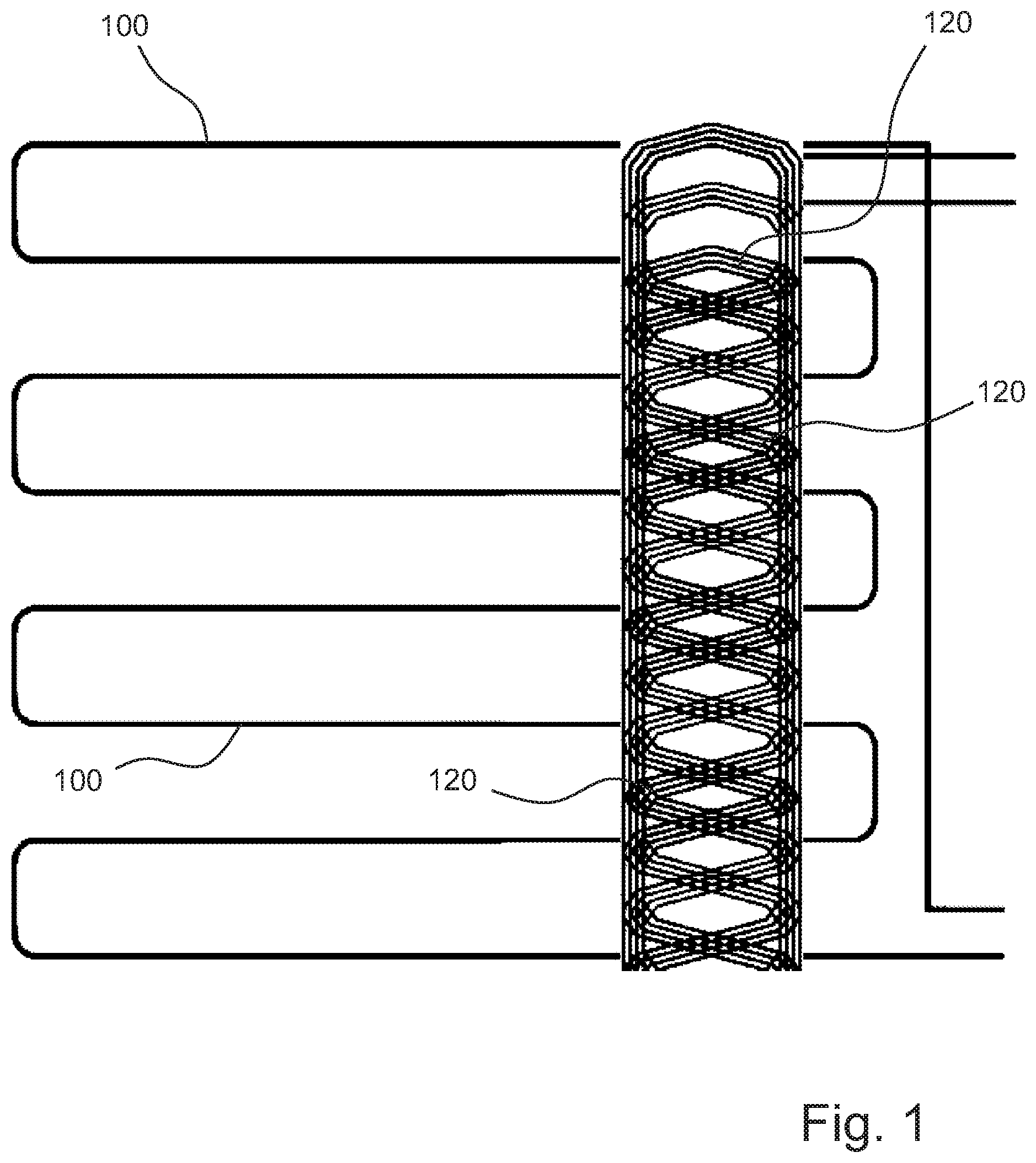
[0019] FIG. 1 shows primary-sided and secondary-sided windings for energy transfer to positionable recipients;
[0020] FIG. 2 schematically shows a circuit and offset windings for energy transfer;
[0021] FIG. 3 schematically shows an autoresonant Royer oscillator having several serially compensated secondary sides for inductively transferring energy and data;
[0022] FIG. 4 shows a meander winding in a simple design having the winding number 3 according to an exemplary embodiment of the invention; and
[0023] FIG. 5 shows the arrangement of three meander windings each having the winding number 3, which come to rest one above the other after folding the flexible carrier along a folding line.
DETAILED DESCRIPTION OF PREFERRED EMBODIMENTS
[0024] In FIG. 1, the energy transfer to positionable recipients is schematically depicted.
[0025] Energy is inductively transferred from a primary-sided meander-shaped winding 100 to secondary-sided meander-shaped windings 120. Both the primary-sided winding and the secondary-sided winding are arranged on a flexible carrier. The meander-shaped winding system of the primary-sided winding is exemplarily depicted in FIG. 1 having one winding. The secondary-sided windings are exemplarily depicted having the winding number 3. Here, the route from left to right corresponds to a length of a rod and the route from above to below to the length of the peripheral surface of the cylinder.
[0026] The inductive energy transfer can take place, for example, with a circuit depicted in FIG. 2. Here, three secondary-sided inductivities 220, 221, 222 lie opposite one primary-sided inductivity 210. A compensation circuit and a rectifier 230, 231, 232 are allocated to each of the secondary-sided inductivities. Depending on the position of the recipient (rotationally), the windings are passed through differently by the magnetic field.
[0027] Due to the geometric construction, one winding will always have the highest induced voltage or the greatest magnetic coupling to the primary side. An intermediate circuit 250 is then supplied by this winding, whereby a constant energy transfer can take place.
[0028] A different kind of energy transfer is depicted in FIG. 3, which shows a so-called autoresonant Royer oscillator having several serially compensated secondary sides. Three secondary inductivities 320, 321, 322 and corresponding rectifiers 330, 331, 332 are allocated to a primary inductivity 310. The advantage of this circuit is that 1 to n recipients having different power can be placed on a rod or on a surface, for example. No additional regulation measures are necessary by an autoresonant power electronics system. The resonance frequency is independent of load. The recipients function in the auxiliary operation.
[0029] The windings provided for this are depicted in FIGS. 4 and 5.
[0030] In FIG. 4, a meander winding 400 having the winding number 3 is depicted. This meander winding 400 is generated by embroidering a high frequency strand 405 using an inherently known embroidery machine onto a flexible material, for example fabric or a different carrier material. For embroidering the strand, it is necessary to draft a winding pattern, which, on one hand, can be converted by the embroidery machine and which, on the other hand, is not subject to damage during the embroidering process. In particular in the region of the inductive energy transfer, namely no errors can occur when embroidering. Here, error means that the high frequency strand is damaged by the embroidery machine. Moreover, when applying the high frequency strand, i.e. when "winding", the mechanical load may not be so great such that the quality of a coil is disadvantageously reduced. Moreover, during the embroidering process, the case must not arise that individual single wires are severed, which leads to a very large deterioration in coil quality, whereby the produced product can no longer be used for energy transfer. Such a puncture when embroidering can occur, in particular, with very complex arrangements. The probability of such a puncture increases with the complexity of the arrangement.
[0031] The winding depicted in FIG. 4 is a meander-shaped arrangement for a three-dimensional construction, which has the great advantage that crossovers 410 are minimized. The crossovers 410 always lie within straight courses of the strand. The embroidering process is here chosen in such a way that a customary embroidery machine skips these regions during the embroidering process. The strand remains stationary without additional punctures, which lie in the region of the crossovers.
[0032] In order to ensure the necessary proximity of single strands to one another, according to a particularly advantageous embodiment, which is depicted in FIG. 5, it is provided that identical meander-shaped windings 510, 520, 530 are arranged on flexible carriers relative to a folding line 501 or (not depicted) further folding lines in such a way that the meander-shaped windings 510, 520, 530 come to rest one above the other offset in relation to one another after folding together the flexible carriers along the line. In this way, very complex winding structures are generated, which can be safely and reliably produced.
[0033] Such an arrangement enables a very effective transfer of electrical energy and of data.
[0034] Although only a few embodiments of the present invention have been shown and described, it is to be understood that many changes and modifications may be made thereunto without departing from the spirit and scope of the invention.
* * * * *
D00000
D00001
D00002
D00003
D00004
XML
uspto.report is an independent third-party trademark research tool that is not affiliated, endorsed, or sponsored by the United States Patent and Trademark Office (USPTO) or any other governmental organization. The information provided by uspto.report is based on publicly available data at the time of writing and is intended for informational purposes only.
While we strive to provide accurate and up-to-date information, we do not guarantee the accuracy, completeness, reliability, or suitability of the information displayed on this site. The use of this site is at your own risk. Any reliance you place on such information is therefore strictly at your own risk.
All official trademark data, including owner information, should be verified by visiting the official USPTO website at www.uspto.gov. This site is not intended to replace professional legal advice and should not be used as a substitute for consulting with a legal professional who is knowledgeable about trademark law.