Substrate Heat Treatment Apparatus
Wang; Hui ; et al.
U.S. patent application number 16/086227 was filed with the patent office on 2020-09-17 for substrate heat treatment apparatus. This patent application is currently assigned to ACM Research (Shanghai) Inc.. The applicant listed for this patent is ACM Research (Shanghai) Inc.. Invention is credited to Fuping Chen, Zhiyou Fang, Hui Wang, Wenjun Wang, Jun Wu, Hongchao Yang.
| Application Number | 20200294825 16/086227 |
| Document ID | / |
| Family ID | 1000004896475 |
| Filed Date | 2020-09-17 |


View All Diagrams
| United States Patent Application | 20200294825 |
| Kind Code | A1 |
| Wang; Hui ; et al. | September 17, 2020 |
SUBSTRATE HEAT TREATMENT APPARATUS
Abstract
A substrate heat treatment apparatus for heat treating a substrate, comprising a bake plate, a plurality of support components, a baffle plate, and a driving device. The bake plate defines at least one gas passage. The plurality of support components support the substrate. The baffle plate is fixed on a top surface of the bake plate. The baffle plate surrounds the substrate and a gap is formed between an inner circumferential wall of the baffle plate and the substrate. A driving device drives the plurality of support components to move up or down. When heat treating the substrate, a hot gas is supplied to the space between the substrate and the top surface of the bake plate through the gas passage of the bake plate, and the hot gas flows out through the gap formed between the inner circumferential wall of the baffle plate and the substrate.
| Inventors: | Wang; Hui; (Shanghai, CN) ; Yang; Hongchao; (Shanghai, CN) ; Wu; Jun; (Shanghai, CN) ; Wang; Wenjun; (Shanghai, CN) ; Chen; Fuping; (Shanghai, CN) ; Fang; Zhiyou; (Shanghai, CN) | ||||||||||
| Applicant: |
|
||||||||||
|---|---|---|---|---|---|---|---|---|---|---|---|
| Assignee: | ACM Research (Shanghai)
Inc. Shanghai CN |
||||||||||
| Family ID: | 1000004896475 | ||||||||||
| Appl. No.: | 16/086227 | ||||||||||
| Filed: | March 18, 2016 | ||||||||||
| PCT Filed: | March 18, 2016 | ||||||||||
| PCT NO: | PCT/CN2016/076681 | ||||||||||
| 371 Date: | September 18, 2018 |
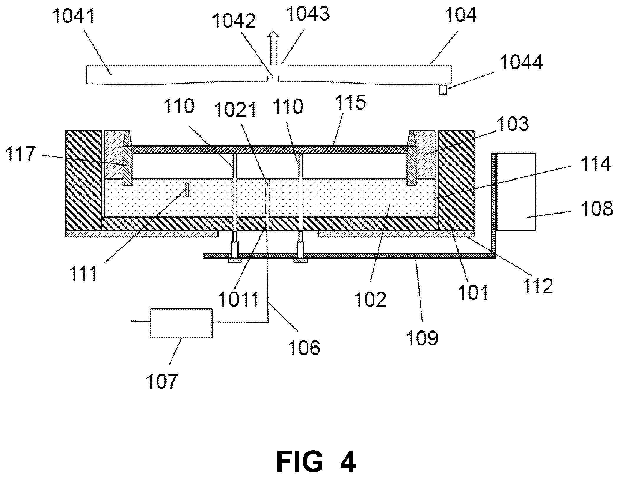
| Current U.S. Class: | 1/1 |
| Current CPC Class: | H01L 21/67248 20130101; F27D 5/0037 20130101; H01L 21/67109 20130101; H01L 21/68742 20130101; F27B 17/0025 20130101 |
| International Class: | H01L 21/67 20060101 H01L021/67; H01L 21/687 20060101 H01L021/687; F27B 17/00 20060101 F27B017/00; F27D 5/00 20060101 F27D005/00 |
Claims
1. A substrate heat treatment apparatus for heat treating a substrate, comprising: a bake plate for defining at least one gas passage; a plurality of support components for supporting the substrate; a baffle plate fixed on a top surface of the bake plate, the baffle plate surrounding the substrate and a gap formed between an inner circumferential wall of the baffle plate and the substrate; and a driving device for driving the plurality of support components to move up or move down; wherein when heat treating the substrate, a hot gas is supplied to the space between the substrate and the top surface of the bake plate through the gas passage of the bake plate, and the hot gas flows out through the gap formed between the inner circumferential wall of the baffle plate and the substrate.
2. The apparatus according to claim 1, further comprising a plurality of position-restricted pins vertically inserted in the baffle plate and the bake plate.
3. The apparatus according to claim 2, wherein every position-restricted pin has a guiding section and a restricting section.
4. The apparatus according to claim 1, wherein the baffle plate is dismountable.
5. The apparatus according to claim 1, wherein the gap is in the range of 0.1 mm-1 mm.
6. The apparatus according to claim 1, further comprising a heat insulation holder, the bake plate disposed in the heat insulation holder, the heat insulation holder defining at least one first gas passage, the first gas passage communicating with the gas passage of the bake plate.
7. The apparatus according to claim 6, wherein one end of the first gas passage of the heat insulation holder communicates with the gas passage of the bake plate and the other end of the first gas passage of the heat insulation holder connects to a gas line which is wrapped by a thermal insulation material.
8. The apparatus according to claim 7, further comprising a gas heater disposed on the gas line for heating the gas in the gas line.
9. The apparatus according to claim 1, wherein the plurality of support components respectively pass through the bake plate, the plurality of support components are fixed on a support arm, the support arm connects to the driving device.
10. The apparatus according to claim 9, wherein every support component has an anti-slip pin and a support shaft, the anti-slip pin has a ball-shaped head for supporting the substrate, the anti-slip pin is mounted on a top end of the support shaft, a bottom end of the support shaft is fixed on the support arm.
11. The apparatus according to claim 1, wherein the baffle plate has a guide plane.
12. The apparatus according to claim 11, wherein the guide plane is tilted and has an angle with the vertical plane, the angle is less than 20 degrees.
13. The apparatus according to claim 1, wherein the material of the baffle plate is ceramic or stainless steel wrapped by a thermal insulation material.
14. The apparatus according to claim 1, further comprising a lift cover disposed above the baffle plate for exhausting mixed gas.
15. The apparatus according to claim 14, wherein the lift cover has a hollow cavity, the lift cover defines an inlet port and an exhaust interface, the inlet port and the exhaust interface communicate with the hollow cavity and the exhaust interface connects to an exhaust system.
16. The apparatus according to claim 15, wherein the lift cover defines a drain port communicating with the hollow cavity.
17. The apparatus according to claim 1, further comprising a temperature sensor disposed in the bake plate.
18. The apparatus according to claim 1, wherein the hot gas is hot inert gas or hot nitrogen.
19. The apparatus according to claim 1, wherein the temperature of the hot gas is the same as the temperature of the bake plate.
20. The apparatus according to claim 1, wherein the temperature of the hot gas is close to the temperature of the bake plate.
Description
FIELD OF THE INVENTION
[0001] The present invention generally relates to a field of semiconductor devices manufacture, and more particularly relates to a substrate heat treatment apparatus for heat treating a substrate.
BACKGROUND
[0002] A photolithography process is an essential part of semiconductor devices manufacture. In the photolithography process, various heat treatments are performed, such as a soft bake after spin coating photoresist on a substrate, a post-exposure bake, and a hard bake after developing. When heat treating the substrate for manufacturing the semiconductor devices, with the improvement of precision of the semiconductor devices, a high degree of temperature uniformity is required during the heat treating process. In a conventional substrate heat treatment apparatus, the substrate is generally placed on a bake plate to heat directly. Although this way of placing the substrate on the bake plate to heat directly is simple, it is hard to guarantee that the substrate is heated evenly because of the warpage of the substrate. Even the substrate looks very flat, but actually, the substrate may still have a certain degree of warpage. Especially, if the substrate is an ultra thin substrate, the warpage of the substrate may be more obviously. As shown in FIG. 12a to FIG. 12c, a substrate 1215 may be upward convex, downward concave, or both. No matter what form of the warpage the substrate 1215 has, if the substrate 1215 is placed on a bake plate 1202 to heat directly, because the distance (h) between any point of the substrate 1215 and the bake plate 1202 is different, and a temperature gradient exists in the space above the bake plate 1202, therefore, the substrate 1215 is heated unevenly during the heat treating process. The temperature of the substrate 1215 is non-uniform after heat treatment, which brings an adverse effect on the quality of the semiconductor devices or even makes the substrate 1215 scrap. FIG. 13 shows the relationship between the heated temperature t(h) of any point of the substrate 1215 and the distance (h) between the any point of the substrate 1215 and the bake plate 1202. It can be seen that the heated temperature t(h) decreases with the increase of the distance (h). Moreover, before the substrate 1215 is heat treated, the substrate 1215 may undergo such as coating, developing processes. When the substrate 1215 is placed on the bake plate 1202 to heat, organic solvent, such as hot photoresist on the substrate 1215 easily flows back and dirties the bake plate 1202.
SUMMARY
[0003] The present invention provides a substrate heat treatment apparatus for heat treating a substrate, comprising a bake plate, a plurality of support components, a baffle plate, and a driving device. The bake plate defines at least one gas passage. The plurality of support components support the substrate. The baffle plate is fixed on a top surface of the bake plate. The baffle plate surrounds the substrate and a gap is formed between an inner circumferential wall of the baffle plate and the substrate. A driving device drives the plurality of support components to move up or down. When heat treating the substrate, a hot gas is supplied to the space between the substrate and the top surface of the bake plate through the gas passage of the bake plate, and the hot gas flows out through the gap formed between the inner circumferential wall of the baffle plate and the substrate.
[0004] As described above, the advantage of the substrate heat treatment apparatus of the present invention at least includes three aspects. Firstly, no matter whether the substrate is warped or not, through supplying the hot gas to the space between the substrate and the top surface of the bake plate to increase the gas convection and form the isothermal layer between the substrate and the top surface of the bake plate, the substrate is heated evenly. Secondly, because of the baffle plate, the substrate center aligns with the bake plate, and for the gap formed between the inner circumferential wall of the baffle plate and the substrate is small enough, the flow of the hot gas around the substrate flowing out from the gap is uniform no matter whether the substrate is warped or not for forming the isothermal layer between the substrate and the top surface of the bake plate. Thirdly, because the gap formed between the inner circumferential wall of the baffle plate and the substrate is small and the hot gas is continuously supplied to the space between the substrate and the top surface of the bake plate during the heat treating process, and mixed gas of the hot gas and organic solvent is exhausted continuously, the organic solvent on the substrate is hard to flow back to the support components and the bake plate, avoiding frequently cleaning the support components.
BRIEF DESCRIPTION OF THE DRAWINGS
[0005] FIG. 1 is a cross sectional view showing a substrate heat treatment apparatus for heat treating a substrate according to an exemplary embodiment of the present invention.
[0006] FIG. 2 is a cross sectional view showing the substrate heat treatment apparatus loading or unloading the substrate.
[0007] FIG. 3 is a cross sectional view showing a substrate heat treatment apparatus for heat treating a substrate according to another exemplary embodiment of the present invention.
[0008] FIG. 4 is a cross sectional view showing a substrate heat treatment apparatus for heat treating a substrate according to another exemplary embodiment of the present invention.
[0009] FIG. 5 is a cross sectional view showing the substrate heat treatment apparatus loading or unloading the substrate.
[0010] FIG. 6 is a cross sectional view showing a substrate heat treatment apparatus for heat treating a substrate according to another exemplary embodiment of the present invention.
[0011] FIG. 7 is a top view showing a baffle plate combining with a plurality of position-restricted pins for a substrate center alignment and a gap formed between an inner circumferential wall of the baffle plate and the substrate.
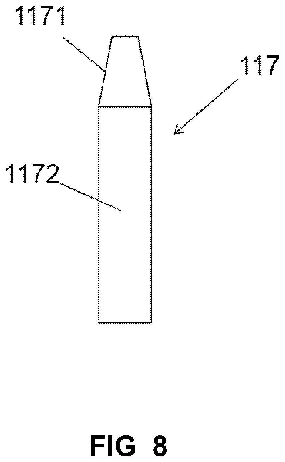
[0012] FIG. 8 is a side view showing the position-restricted pin.
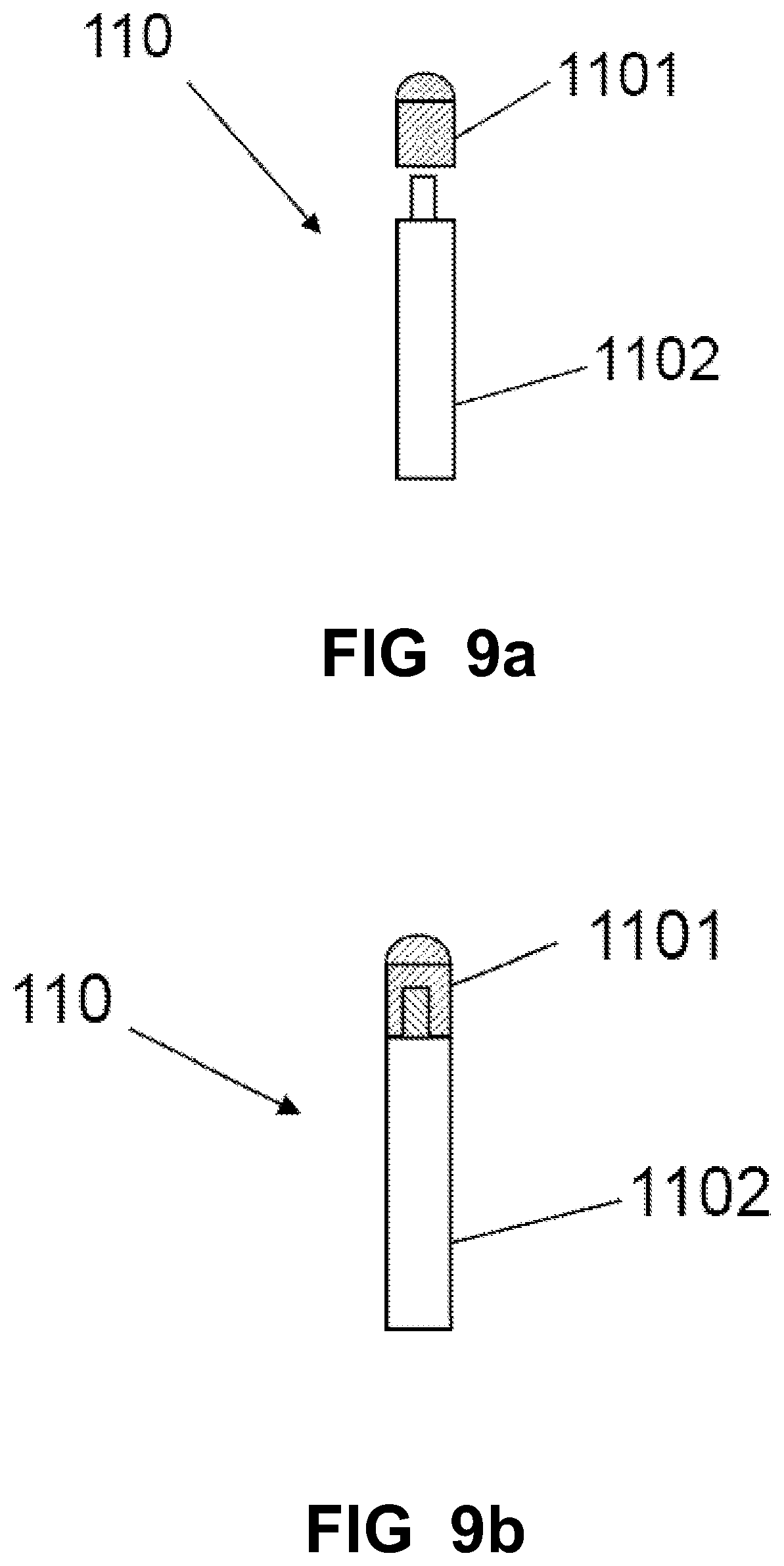
[0013] FIG. 9a is an exploded view of a support component of the substrate heat treatment apparatus of the present invention.
[0014] FIG. 9b is a perspective view of the support component of the substrate heat treatment apparatus of the present invention.
[0015] FIG. 10a to FIG. 10c show using the substrate heat treatment apparatus of the present invention to heat treat a substrate which is upward convex, downward concave or both.
[0016] FIG. 11 shows the relationship between the heated temperature t(h) of any point of the substrate and the distance (h) between the any point of the substrate and a bake plate when using the substrate heat treatment apparatus of the present invention to heat treat the substrate.
[0017] FIG. 12a to FIG. 12c show using a conventional substrate heat treatment apparatus to heat treat a substrate which is upward convex, downward concave or both.
[0018] FIG. 13 shows the relationship between the heated temperature t(h) of any point of the substrate and the distance (h) between the any point of the substrate and a bake plate when using the conventional substrate heat treatment apparatus to heat treat the substrate.
DETAILED DESCRIPTION
[0019] Referring to FIG. 1, a substrate heat treatment apparatus for heat treating a substrate according to an exemplary embodiment of the present invention is illustrated. The substrate heat treatment apparatus has a heat insulation holder 101, a bake plate 102, a baffle plate 103, a lift cover 104, and a plurality of support components 110. The bake plate 102 is disposed in the heat insulation holder 101 for heating a substrate 115. The bake plate 102 can be a circular electric heating panel which is made of aluminum. During the heat treating process, the temperature distribution on a top surface of the bake plate 102 is very uniform. The size of the bake plate 102 is determined by the size of the substrate 115 in order to heat treat the substrate 115 with different size. For example, in view that the size of the substrate 115 which is commonly used now is 8 inch or 12 inch, the diameter of the bake plate 102 can be 350 mm. Therefore, the bake plate 102 can heat treat the substrate 115 which size is 8 inch or 12 inch.
[0020] The bake plate 102 is received in the heat insulation holder 101 and the center of the bake plate 102 is aligned with the center of the heat insulation holder 101. An interval 114 is formed between a side wall of the bake plate 102 and the heat insulation holder 101 for avoiding the temperature characteristic of the side wall of the bake plate 102 being affected and the heat insulation holder 101 being squeezed by the bake plate 102 when the bake plate 102 expands by heat. The heat insulation holder 101 is made of high-temperature-resistant material, such as ceramic. The center of the heat insulation holder 101 defines a first gas passage 1011. The first gas passage 1011 passes through the heat insulation holder 101. The center of the bake plate 102 defines a second gas passage 1021. The second gas passage 1021 passes through the bake plate 102 and communicates with the first gas passage 1011. One end of the first gas passage 1011 communicates with the second gas passage 1021 and the other end of the first gas passage 1011 connects to a gas line 106 which is wrapped by a thermal insulation material. A gas heater 107 is disposed on the gas line 106 for heating the gas in the gas line 106, so that a hot gas is supplied to the space between the substrate 115 and the top surface of the bake plate 102 through the first gas passage 1011 and the second gas passage 1021. The substrate 115 is supported above the top surface of the bake plate 102 by the plurality of support components 110 which respectively pass through the heat insulation holder 101 and the bake plate 102. The plurality of support components 110 are fixed on a support arm 109. The support arm 109 connects to a driving device 108. The driving device 108 drives the support arm 109 to move up or down, which brings the plurality of support components 110 to move up or down, which further brings the substrate 115 to move up or down for adjusting the distance between the substrate 115 and the top surface of the bake plate 102 or for loading or unloading the substrate 115. The driving device 108 can be a motor.
[0021] As shown in FIGS. 9a and 9b, in an embodiment, the support component 110 has an anti-slip pin 1101 and a support shaft 1102. The anti-slip pin 1101 has a ball-shaped head for supporting the substrate 115. The anti-slip pin 1101 is mounted on a top end of the support shaft 1102 by a way of, such as thread locking, so that it is easy to disassemble and replace the anti-slip pin 1101. Because the anti-slip pin 1101 has an anti-slip function, therefore, the anti-slip pin 1101 prevents the substrate 115 from horizontally moving when the substrate 115 is placed on the anti-slip pin 1101 and moves up or down. A bottom end of the support shaft 1102 is fixed on the support arm 109.
[0022] The baffle plate 103 is fixed on the top surface of the bake plate 102, and the baffle plate 103 can be dismountable. The baffle plate 103 surrounds the substrate 115 and a gap 113 is formed between an inner circumferential wall of the baffle plate 103 and the substrate 115. The gap 113 is in the range of 0.1 mm-1 mm, and preferably 0.1 mm-0.5 mm. The baffle plate 103 has a guide plane 1031 for conveniently loading the substrate 115 on the support components 110. The guide plane 1031 is tilted and has an angle with the vertical plane. The angle is less than 20 degrees, and preferably is 15 degrees. The material of the baffle plate 103 can be ceramic or stainless steel wrapped by a thermal insulation material.
[0023] The lift cover 104 is disposed above the baffle plate 103. The lift cover 104 has a hollow cavity 1041. The lift cover 104 defines an inlet port 1042 and an exhaust interface 1043. The inlet port 1042 and the exhaust interface 1043 communicate with the hollow cavity 1041 and the exhaust interface 1043 connects to an exhaust system. Through the inlet port 1042 and the exhaust interface 1043, mixed gas generated during the heat treating process can be exhausted. The lift cover 104 also defines a drain port 1044 communicating with the hollow cavity 1041.
[0024] A temperature sensor 111 is disposed in the bake plate 102 for monitoring the temperature of the bake plate 102. The temperature sensor 111 can be a thermocouple. The heat insulation holder 101 is disposed on a pedestal 112.
[0025] When using the substrate heat treatment apparatus of the present invention to heat treat the substrate 115 which has undergone, for example, spin coating photoresist, as shown in FIG. 2, the driving device 108 drives the support arm 109 to move up to make the plurality of support components 110 arrive at a loading position. Then the substrate 115 is placed on the plurality of support components 110 by using, such as a robot arm 116. The driving device 108 drives the support arm 109 to move down to make the substrate 115 arrive at a process position. There is a distance between the substrate 115 and the top surface of the bake plate 102. So the substrate 115 doesn't contact the top surface of the bake plate 102. The size of the distance is determined by the process requirement. Hot inert gas or hot nitrogen, is supplied to the space between the substrate 115 and the top surface of the bake plate 102 through the first gas passage 1011 and the second gas passage 1021. Taking the hot inert gas for example, the temperature of the hot inert gas can be the same as the temperature of the bake plate 102, or close to the temperature of the bake plate 102. Through supplying the hot inert gas to the space between the substrate 115 and the top surface of the bake plate 102, the gas convection is increased and an isothermal layer is formed between the substrate 115 and the top surface of the bake plate 102, which makes the rate of heat conduction be same and destroys the temperature gradient in the space above the top surface of the bake plate 602, therefore, the substrate 115 is heated evenly during the heat treating process no matter whether the substrate 115 is warped or not. The mixed gas generated during the heat treating process is exhausted into the hollow cavity 1041 through the inlet port 1042 and the mixed gas in the hollow cavity 1041 is exhausted out through the exhaust interface 1043. Before the substrate 115 is heat treated, the substrate 115 may undergo such as coating, developing processes. When the substrate 115 is heat treated, organic solvent, such as photoresist on the substrate 115 is volatilized and exhausted into the hollow cavity 1041 along with the hot inert gas. The organic solvent is condensed in the hollow cavity 1041 and is drained out from the drain port 1044. Because the gap 113 formed between the inner circumferential wall of the baffle plate 103 and the substrate 115 is small enough and the hot inert gas is continuously supplied to the space between the substrate 115 and the top surface of the bake plate 102 during the heat treating process, the organic solvent on the substrate 115 is hard to flow back to the support components 110 and the bake plate 102. Moreover, the substrate heat treatment apparatus of the present invention has the baffle plate 103 fixed on the top surface of the bake plate 102, when the substrate 115 is heat treated by using the substrate heat treatment apparatus of the present invention, the substrate 115 is easy to center align with the bake plate 102. When the robot arm 116 loads or unloads the substrate 115, there is no need to center align any more. Besides, for the gap 113 formed between the inner circumferential wall of the baffle plate 103 and the substrate 115 is small enough, the flow of the hot inert gas around the substrate 115 flowing out from the gap 113 is uniform no matter whether the substrate 115 is warped or not for forming the isothermal layer between the substrate 115 and the top surface of the bake plate 102. After the substrate 115 is heat treated, the driving device 108 drives the support arm 109 to move up to make the plurality of support components 110 arrive at an unloading position. The robot arm 116 takes away the substrate 115 from the support components 110 and the hot inert gas is stopped to supply.
[0026] As shown in FIGS. 10a to 10c and FIG. 11, even if the substrate 115 is upward convex, downward concave or both, because of supplying the hot inert gas to the space between the substrate 115 and the top surface of the bake plate 102 to increase the gas convection and form the isothermal layer between the substrate 115 and the top surface of the bake plate 102, although the distance (h) between any point of the substrate 115 and the bake plate 102 is different, the substrate 115 is heated evenly and the temperature of the substrate 115 is uniform after heat treatment.
[0027] As shown in FIG. 3, in another embodiment, the heat insulation holder 101 and the bake plate 102 respectively define a plurality of first gas passages 1011 and a plurality of second gas passages 1021 for supplying the hot gas to the space between the substrate 115 and the top surface of the bake plate 102. The plurality of first gas passages 1011 respectively connect to the gas line 106.
[0028] As shown in FIG. 4 and FIG. 5, in another embodiment, for avoiding the substrate 115 misaligning to induce the substrate 115 to contact the baffle plate 103, a plurality of position-restricted pins 117 are vertically inserted in the baffle plate 103 and the bake plate 102. The plurality of position-restricted pins 117 are uniformly distributed along the inner circumferential wall of the baffle plate 103. As shown in FIG. 8, every position-restricted pin 117 has a guiding section 1171 and a restricting section 1172. As shown in FIG. 7, when the substrate 115 is placed on the support components 110 and moves down to the process position along the guiding sections 1171, the substrate 115 is restricted by the restricting sections 1172, so that the substrate 115 can center align with the bake plate 102 and the gap 113 is formed between the inner circumferential wall of the baffle plate 103 and the substrate 115.
[0029] As shown in FIG. 6, comparing to the embodiment disclosed in FIG. 4 and FIG. 5, the heat insulation holder 101 and the bake plate 102 in another embodiment disclosed in FIG. 6 respectively define a plurality of first gas passages 1011 and a plurality of second gas passages 1021 for supplying the hot gas to the space between the substrate 115 and the top surface of the bake plate 102. The plurality of first gas passages 1011 respectively connect to the gas line 106.
[0030] As described above, the advantage of the substrate heat treatment apparatus of the present invention at least includes three aspects. Firstly, no matter whether the substrate 115 is warpping or not, through supplying hot gas to the space between the substrate 115 and the top surface of the bake plate 102 to increase the gas convection and form the isothermal layer between the substrate 115 and the top surface of the bake plate 102, the substrate 115 is heated evenly. Secondly, because of the baffle plate 103 and the position-restricted pins 117, the substrate 115 automatically center aligns with the bake plate 102. Besides, for the gap 113 formed between the inner circumferential wall of the baffle plate 103 and the substrate 115 is small enough, the flow of the hot gas around the substrate 115 flowing out from the gap 113 is uniform no matter whether the substrate 115 is warped or not for forming the isothermal layer between the substrate 115 and the top surface of the bake plate 102. Thirdly, because the gap 113 formed between the inner circumferential wall of the baffle plate 103 and the substrate 115 is small and the hot gas is continuously supplied to the space between the substrate 115 and the top surface of the bake plate 102 during the heat treating process, and mixed gas of the hot gas and organic solvent is exhausted continuously, the organic solvent on the substrate 115 is hard to flow back to the support components 110 and the bake plate 102, avoiding frequently cleaning the support components 110.
[0031] The foregoing description of the present invention has been presented for purposes of illustration and description. It is not intended to be exhaustive or to limit the invention to the precise form disclosed, and obviously many modifications and variations are possible in light of the above teaching. Such modifications and variations that may be apparent to those skilled in the art are intended to be included within the scope of this invention as defined by the accompanying claims.
* * * * *
D00000
D00001
D00002
D00003
D00004
D00005
D00006
D00007
D00008
D00009
D00010
D00011
D00012

D00013

XML
uspto.report is an independent third-party trademark research tool that is not affiliated, endorsed, or sponsored by the United States Patent and Trademark Office (USPTO) or any other governmental organization. The information provided by uspto.report is based on publicly available data at the time of writing and is intended for informational purposes only.
While we strive to provide accurate and up-to-date information, we do not guarantee the accuracy, completeness, reliability, or suitability of the information displayed on this site. The use of this site is at your own risk. Any reliance you place on such information is therefore strictly at your own risk.
All official trademark data, including owner information, should be verified by visiting the official USPTO website at www.uspto.gov. This site is not intended to replace professional legal advice and should not be used as a substitute for consulting with a legal professional who is knowledgeable about trademark law.